Ericsson ORION, various notes
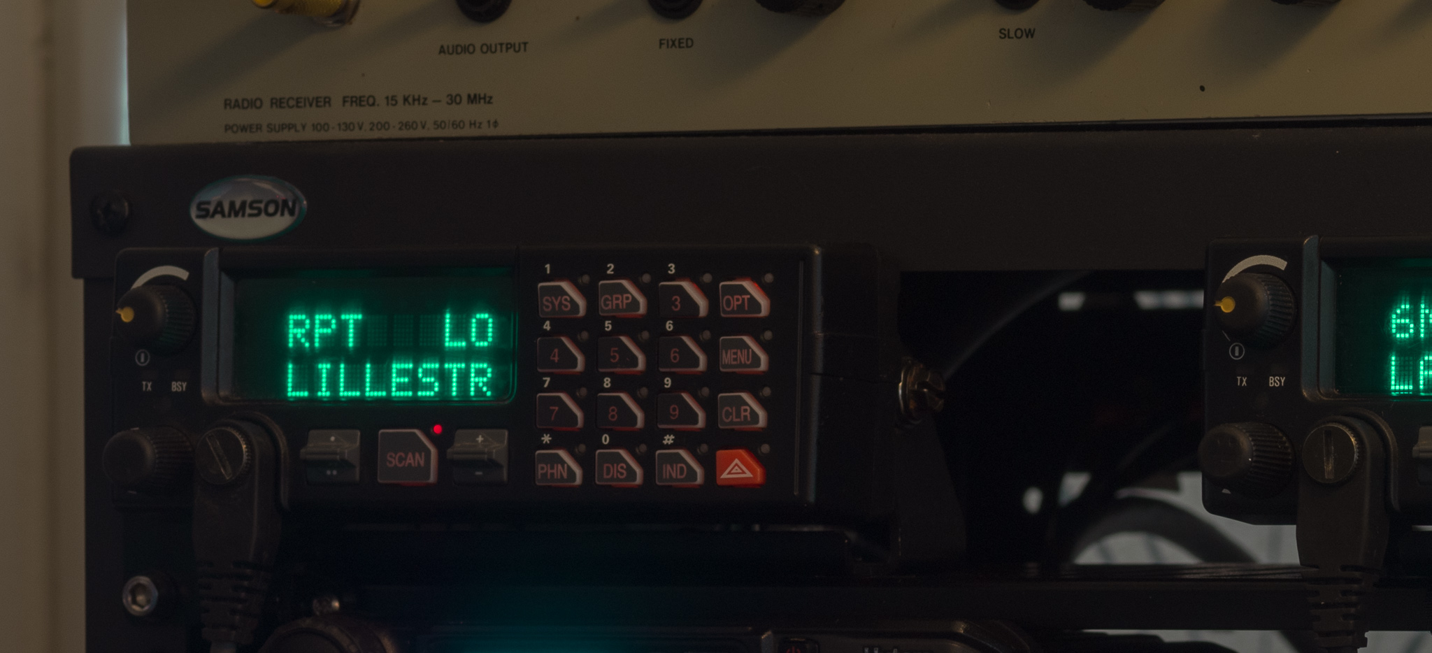
A collection of various info and thoughts about the Orion radio system, also sold under GE and M/Acom brandings.
Table of Contents
Hardware Notes
You need a Torx set to open the radios, T20, 10, 8, 6 are specific sizes you'll need. Basically all screws are Torx head.
Beware of the gaskets when assembling, and lube these with silicon grease (as specified in the service manuals).
First power-up: check the switch on the Control-IF board - the little switch selects if the ignition sense line is used to power up the radio or not.
Adjustment Points
It's ok to adjust the synth and IF/CPU board. Ericsson specifies that touching the trimmers on the PA boards will void the warranty and should never be done outside the factory.
I haven't had to adjust the PA trimmers — the software trim was fine.
Powering the US Models
The US models are powered using a separate connector (due to the higher output power compared to the EU models).
I made a mod to convert this to a 30 A Powerpole connector by using some M3⨉6+6 brass spacers and a simple 3D printed part – this is questionable for the 110 W model but probably fine for 60 W and below.
Programming Quirks
First, find the GE-Orion Yahoo! Group, they have discussions and many required files and documents. You'll need programmer software version 17 or 18 to follow along.
With the closure of Yahoo! Groups, the relevant information is now found in GE-Orion@groups.io
Also find more documentation here:
http://www.repeater-builder.com/ge/lbi-master-list.html
When the RIB is connected to the radio and a serial port is connected, turning on the radio will put it into programming mode.
Programming
Find the document "Radio Flash and DSP Codes (rev20)" to cross reference what firmware is the latest available.
The function in ProGrammer to download the firmware from the radio is unreliable, don't use it (it was removed entirely in later versions according to a document I found).
Firmware files are named a specific way e.g. OG30400, the software uses parts of these names to determine what firmware can go into what radio processor board model. Do not rename the files.
Out Of Band mods
I tried to convert one radio-board from 150-174 to a 136-155 MHz board. This messed up the radio and I still haven't fixed it. Just wait to get approved in the Yahoo group to get the .sc4 files and use these files, once set up the files don't require any extra programming steps.
Note that .sc files are for an older version of the software and have to be slightly rewritten to work as .sc4 files.
The band-split for VHF is usually 150-174 MHz, you can use a .sc4 file with the programmer to shift the program down a bit. The .sc4 files for various radios are available in the GE-Orion group.
To use a .sc4 file, go to Options/General Options and select the appropriate .sc4 file to use. A SC4 file will shift the frequencies you entered by some amount like 6 or 10 MHz when programming. This allows the use of a 150-174 radio as a 144-168 MHz radio, and others.
VHF mid band notes:
The 150-174 model will generally pull down to 144 MHz on both TX and RX with only a simple adjustment of the VCO trimmer caps. There is a VCO voltage test point available without removing the shielding can.
Sensitivity will vary from device to device when modded, increasing capacitor sizes very slightly in the last filter stage tends to resolve sensivitity issues. The trimming range with the trimmer caps is very slight and often not enough to get the best sensitivity at 144 MHz.
I don't have a fixed set of instructions but adding a few 0.5 and 2.2 pF capacitors around the filters was enough to pull it down to 144 MHz. I also did some tuning with the RSSI output (which you have to solder a wire to on the IF board to get a reading from - it's not available externally).
The US 110W models will not go much below 25-30 W at the lowest output power - the efficiency at this output level is very low compared to a lower power model.
VHF Low Band 50 MHz
There are detailed instructions in the Yahoo Group describing the conversion to 50-52 MHz operation.
I was fairly painless in my case.
Narrow-Band mod
Some later models (some US models I got off eBay) have switchable IF boards - these can do 25 and 12.5 kHz channels at the same time. The RF Board field in the radio information will have a swb suffix if it can do switchable bandwidth.
To convert a non-switchable model to Narrow, I replaced the 2nd IF filter with narrower types.
I used LT455GW filters for the FL503 position - replace R523 and R552 with 2 kΩ
Optionally the FL504 position can be changed to e.g. a LT455FU (slightly wider - by design) and replace R556, R557 with 2 kΩ.
After this, perform a full IF alignment.
To ensure that subtones work properly, you must adjust the audio gain. I adjusted it by tuning a channel with tone-squelch and applying the tone with a low deviation. I was able to detect a subtone at 200 Hz deviation with some tuning – the requirement is around 300 Hz deviation to detect a tone.
Replace R563 with e.g. 10-15 kΩ if you can't get the subtone detection to work, or look up the adjustment spec in the Service Section documents.
Finally, adjust the Tracking Data TX deviation and TA TX deviation.
Alignment
General
The software tool to align the radio is called Radio Maintenance and is part of the ProGrammer software package.
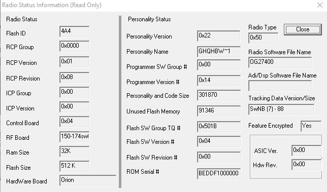
Before doing anything, read the Tracking Data and Feature Data, and save these to files in case you mess up.
Also a good idea to open the Radio Information tab and take a screenshot for each radio. This information is useful.
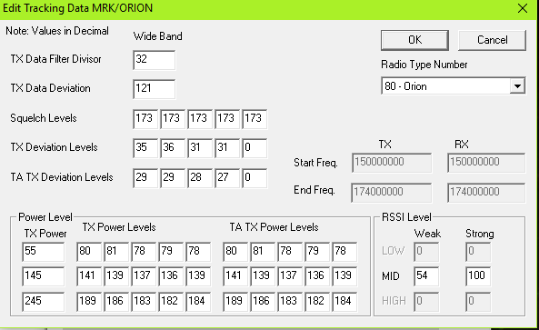
Tracking Data Settings
The setting for TX Deviation is set by TX Deviation Levels, the equivalent TA TX Deviation level setting is used only in the Talkaround mode. I ended up around 20-30 for 2.5 kHz peak deviation.
Squelch levels are adjustable in the Squelch menu in the radio, but a level of 5-10 should be the normal range. I set the squelch to close at 8-10 dB SINAD with a squelch setting of 5. I ended up around 150 for squelch.
To test multiple power levels you have to make several Systems with a specific power levels — there is no way to change power levels from the radio control head in the Orion system (later radio types can do that).
With the TQ-3370 RIB box you can easily hook up the radio to a service monitor to perform adjustments. The box is powered by the radio when on so you don't need to plug in power to the box.
I haven't found any way to change the CTCSS, 5-tone, or DTMF deviation level — it seems to be fixed relative to the peak voice level. The TX Data Deviation seems to have no effect on these tone signals — it's probably only for digital data systems like EDACS.
I have found no information in the manuals on how to set the RSSI levels – nor exactly what they're used for (they're probably used for digital systems).
General Programming
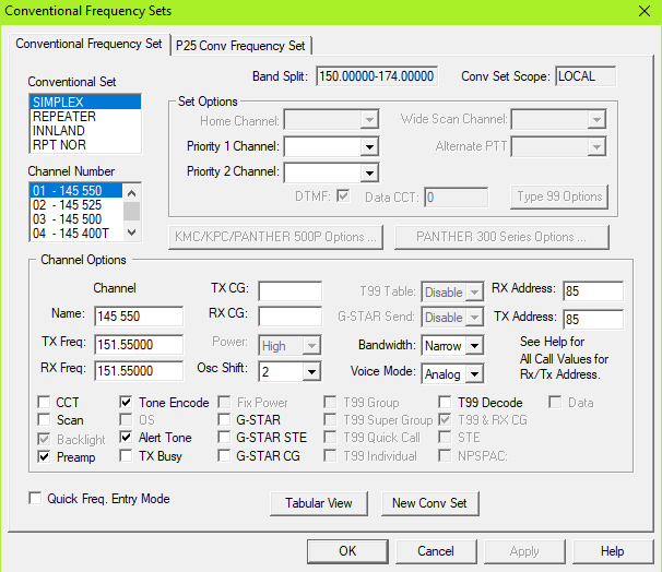
Channels and Sets
Channels are defined as Conventional Frequency Sets. You make a Set, then add channels. The frequencies must be offset by some amount if you're using a .sc4 file.
Preamp can be enabled to get the best sensitivity on some models.
If you have a 5-tone system you have to enable Tone Encode per channels (it's greyed out until you have a system that can use it).
CTCSS is called "CG" in the system, frequencies can be entered manually. To only send a tone with noise-squelch receive, don't enter a RX CG.
Enable "STE" for channels with subtone squelch – this allows a subtone reverse pulse to be detected for a quieter squelch close. I'm not entirely sure if the radio sends a subtone reverse in this case, it seems to sometimes but the documentation is unclear. There's no selection between 120 and 180°.
CCT enables the TX time-out feature.
Systems
In a System Setup, add a Conventional System, and define one of the Sets as the frequency set.
The Power Level setting is usually default set to "MAX". It can be set as a number — this number is weird, and probably related to the defined levels in the tracking data. Setting it to 1 will usually give you the lowest output power. Some radios might have a medium as well.
To allow switching between high and low, I just made two systems per Set.
To use DTMF auto-dial you have to make a Phone Set first, then select that set for your System. Also enable the DTMF checkbox per System.
The DTMF checkbox controls if you can live-dial with the keypad as well.
Other Settings
There are a lot of settings — these radios are complicated.
DTMF Options
DTMF options define the parameters for the DTMF auto-dial.
It doesn't seem like the radio support ABCD keys at all (not even pre-programmed).
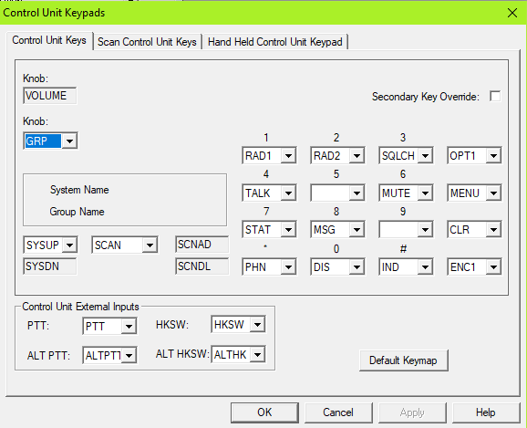
Control Unit Keypad Options
Allows definition of the keys for the relevant Control Head. Note that if you change this, you have to specifically select the option to program the control head during normal programming (checkboxes under Mobile Settings in the window where you select firmware files).
Most of the functions you can select don't do anything in the Orion system — the help system tells you this.
Squelch and ENC1 are useful to define as keys. For low band, NOIS controls the noise blanker.
Keypad Options
Hookswitch options are here — I disabled most things here. You can define things like hookswitch-stop or start scan if you want.
Power Up Options
This defines what is set up when you turn on the radio. Most operators seem to like resetting the squelch level on startup.
Programmable Menus
Most of the menus are not available on the Orion — check the help files.
Squelch, Backlight, Talkaround, Noise Blanker (lowband), and Features, are things that are useful to have.
The menus are defined entirely in the radio so you don't need to update the control unit programming to change these.
Scan Options
I set mine up approximately like this:
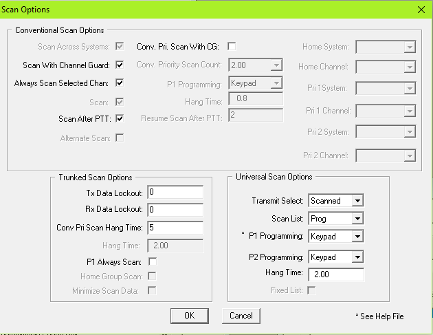
Scan After PTT may be switched off — this disables the scanner when you transmit. This makes most sense if you set the Transmit Selected to Scanned instead of pre-defined (as is typical for commercial/EMS use).
Transmit Selected defines what channel you transmit on when the scanner is active — Scanned means it will transmit on whatever channel you just heard.
"Scan With Channel Guard" means that subtone squelch will be used when defined — without it it will use noise squelch in scan mode.
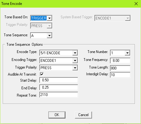
Tone Encode
If you want 1750 tones available, you can configure a 5-tone system here.
This system will send a 5-tone sequence starting with 8 (1747 Hz) for 800 ms when the ENCODE1 key is pressed (Which must be configured in your control unit keypad — I use Emergency for this).
Tone Number is what number in the sequence you're setting, Frequency is the 5-tone index number in this case.
You must also enable Tone Encode per channel in all sets to be allowed to transmit the tone, and make sure to define a control head button to perform this function.
In Use
Scanner
The Orion has a good scanner — it has very fast channel switching. There are several settings for the scanner as well.
The Control Unit has dedicated buttons to control the scanner — the Scan key will turn on the scanner and it has a LED to indicate that it's working. You can also change how it behaves when keying up.
The Scan tumbler thing is used to add or delete channels from the scan sequence. When pressing up "S" means it's part of the scan list — pressing up again will set it as Priority 2 scan - again will set it as Priority 1.
Priority 1 and 2 will always be scanned — 2 is around once per second. This happens fast enough for P2 scan that it doesn't bother me all that much, so I define my local repeater as P2 scan so I can always hear a call there.
If it says "S CG" that means that subtones will also be checked.
The scan feature can not scan across Sets — you must put all your scanned channels in a single set.
It does not appear to support Voting Scan with FM channels, it is definitely possible for EDACS.
Control Heads and Cables
Documentation on cables and such can be found in the Installation Manual, and the Yahoo Group.
DIY Cable
The cable for the Orion is complicated with multiple different wire sizes and shields.
The cables for the EU and US variants are different — the EU variant has the opposite gender on the 37 pin D-Sub and a slightly different pinout.
The same 25 pin pinout is used however.
To make cables, see documents LBI-38992 and LBI-38994 for pinouts.
To make a minimum viable control cable yourself, you must connect the following signals:
RS485+/-, GND, IGN SEN, MIC_HI/ALO, CTL ON, RQST, SPKR1/2, SW A+, CUTST
I built a few cables using a 6 pair (12 conductor) AWG22 industrial control cable from Alpha Wire. The cable I found had individual foil shielding per pair and a separate drain wire per pair — the drain wires were soldered together at each end and connected to pin 7 GND.
This worked fine for my 2-3 meter long cables. I wouldn't suggest using anything thinner than AWG24 unless the cable is very short.
Note: EU models supply power via the 37 pin D-Sub, so you have to hook up that as well.
System Hookup
You would normally connect the IGN Sens to your switched 12 V to enable the radio (make sure to check the little switch on the control-IF board if you want to use this).
Speakers are 4 ohm bridged (differential) — be careful connecting small speakers since the output power can be very high. A 1-2 W 4 Ω speaker at full volume will last around 2 seconds.
Both of those are normally connected to the control unit OPT connector instead of directly to the radio.
Dual Radio
In late 2023 I finally managed to find a UHF Orion from the US. I hooked this radio up and configured it as a secondary, with a modified cable used to connect both up at the same time.
The information in LBI-38901T was used when making the required configuration changes, and I modified my cable i.a.w. Figure 55 (19B802554P10). This took a few attempts, as I've noted above these radios can be picky wrt. wire gauges so shorter wires are preferable.
In dual radio mode you can operate full duplex if desired, the RX AF from the non-transmitting radio is not required to be muted. The user interface does slow down, and scanning both radios seems to cause a bit of lag.
You can program some buttons to change which radios is active, and the light next to e.g. RAD1 and RAD2 will indicate the state of the currently active radio (the one that is selected for transmit/control). The display will switch based on RX activity, but the TX/BSY lights only reflect the currently selected radio. It can be a bit confusing.
Over all I'd suggest that just having two control heads may be a better user experience if you have room.
It should be possible to cross-band repeat in a two radio setup, but I haven't tested this.
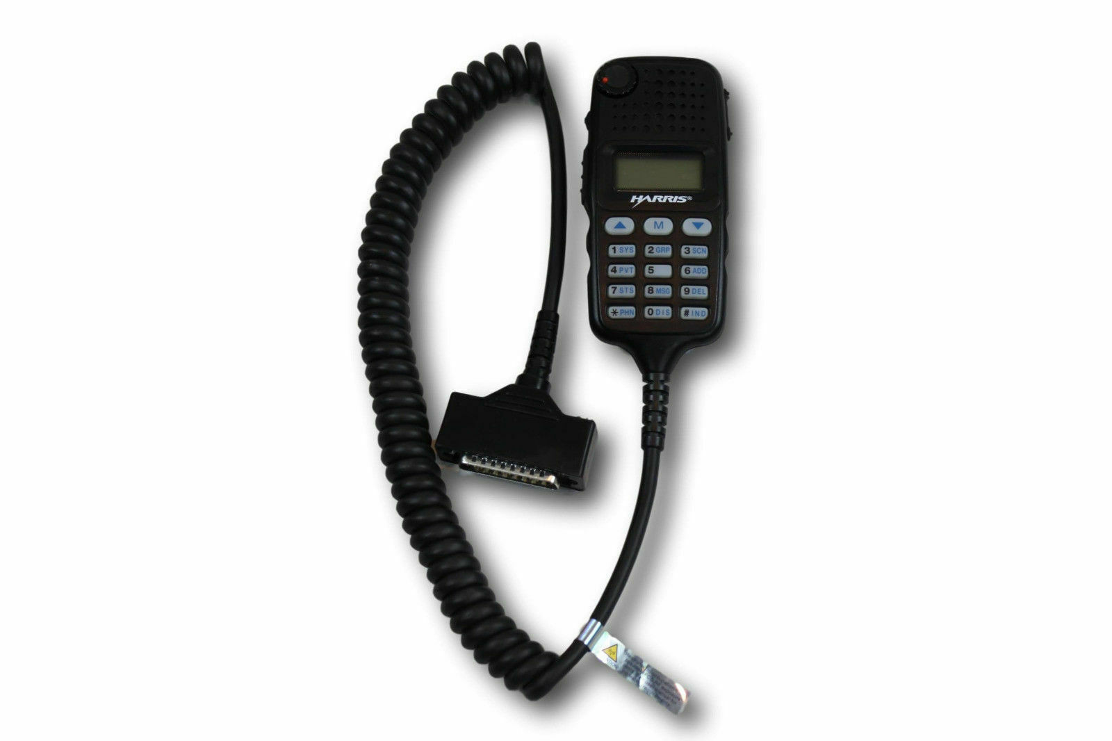
Hand Held Controller
The HHC is a very cool handheld device about the size of a DTMF mic that has a full LCD display and almost all the keys available on the normal Control Unit (except the scan keys, which are assigned differently).
Documentation including schematics for the Orion/M7100 HHC can be found in the Yahoo group.
The HHC unit does NOT connect directly to the 25 pin connector going to the normal Control Units — it required an adapter cable like the CA101619V1. This cable changes around a handful of pins and splits out most signals to the same OPT connector found on the normal Control Unit to connect your speaker and other signals.
I made an adapter PCB to replace this cable, it's a fairly simple adapter to make. The technical data package for this adapter is here: HHC_IF_TDP.zip. It includes schematics, gerbers, and a STEP model of the PCA.
Microphones
Microphones for the normal control units use a weird plug. I wouldn't bother trying to hack together something for that plug. The control head side of the plug is called "B19/5JWHZ00048" and seems to be a custom part that can't realistically be bought.
Loose D-Sub male pins will fit loosely and can be poked in for testing. The pin diameter is 1.00 mm for the original connector, and my D-Sub pins measure ~0.95 mm or so.
The table below shows the pinout looking into the control panel:
| 6/SWA+ (14 V) | 5/SPK- | 4/SPK+ | ||
| 7/GND | 3/PTT | |||
| 8/CG DIS | 2/Mic- | |||
| 9/ALT PTT | 1/Mic+ |
The standard hand-mic is a dynamic 600 Ω mic with a preamplifier — there are also desktop microphones available that were used with base stations. They also work with the mobile control units. The specification for the radio transmitter itself is listed as 55-110 mVrms, suggesting that you could connect a consumer line level output to the microphone lines.
If you don't have a mic and want to hack something up, the microphone lines are available in the OPT plug on the remote control head as MIC HI and ALO (return). There are also dedicated EXTMIC lines that might be usable but probably require specific programming to enable in the codeplug.
Keying is done digitally, I think it should be possible to wire the PTT line to one of the digital inputs in the OPT connector and program the radio to use them as PTT. You could also run a wire from the PTT line in the control head over to a spare pin in the OPT plug. The OPT plug also has speaker lines available so if you wanted to connect speaker-mic/handset to the radio this seems like the way to do it.
Feature Keys
I don't have much to say about feature keys for these radios, there is a system to allow/disallow certain functionality.
For an analog Orion system there don't seem to be any special/unusual keys that are useful.
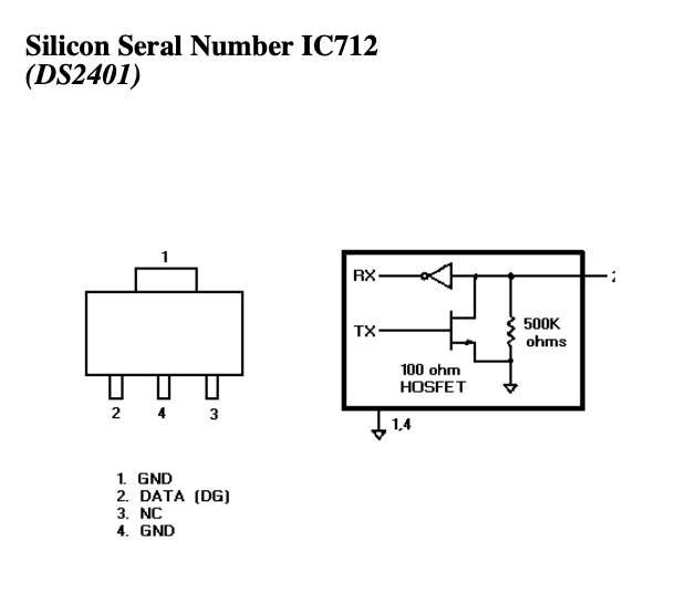
The feature keys are encrypted to a specific radio serial number, this serial number is stored in a DS2401 serial number IC. The way to bypass this system would be to e.g. replace the DS2401 with a processor that reports the serial number of a radio that you have the required keys for. This would effectively let you clone a radio, duplicating the features.