HP 3456A 50/60 Hz Modification — the easy way
This article is about modifying the HP 3456A voltmeter for 50 Hz operation.
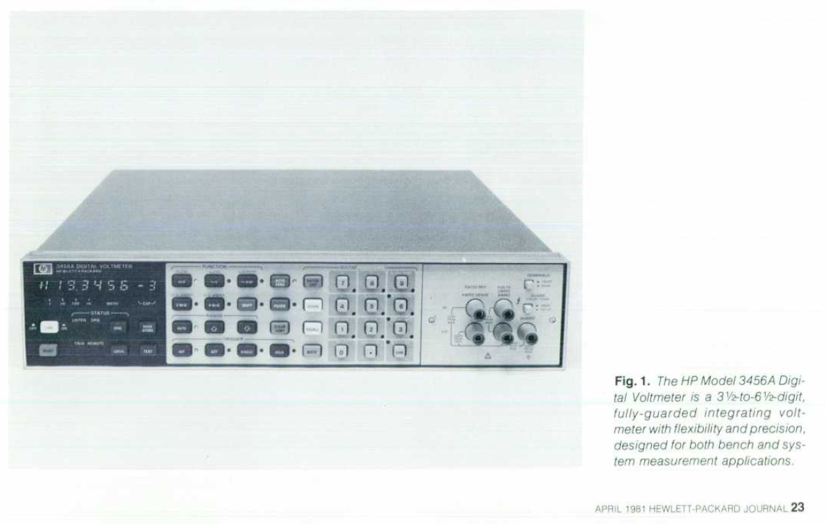
The HP 3456A is a respectable "System DVM" voltmeter introduced around 1981, it was quite popular for use in automatic test stations with the HP-IB interface option. The voltmeter was a "low-cost" unit compared to earlier units, but it was still the high performance option in its class for many years.
As part of the HP 3054 Measurement system (a full desk + rack + minicomputer) the HP 3456A cost $3770 in 1981. Adjusted for 2020 inflation this is equivalent to approximately $10'000.
Xdevs.org has an article about this meter with some stability measurements etc. https://xdevs.com/fix/hp3456a/. I didn't do any of the mods listed in there though.
It's a 6.5 digit voltmeter capable of 100 nV resolution in DC volt mode, ranges below 10 V are Hi-Z (>100 GΩ) making it very good at measuring high impedance loads. In fact you can use 10:1 oscilloscope probes with an adapter in in the 1 and 10 V ranges without any real loss of accuracy. It also features 4-wire Ω measurement and a decent AC RMS mode.
Based on my measurements, they keep their calibration quite well, and checking against transfer standards over the last 6 years I haven't had to make any adjustments. Calibration is all analog, meaning there's no ROM/battery backed RAM to fail.
The instruments are quite large, but if you have the room for them they're great instruments to keep in a rack next to your bench.
I have 3 of these instruments (they were free), and two of them are 60 Hz models. While the mains input voltage can simply be set to whatever you want, the 60 Hz model has a 60 Hz notch filter[0] to reject mains coupling. When used with 50 Hz power the instrument will give a slight "wobble" to readings (typically a mV or two).
There's no way to adjust or switch the mains frequency, this was set by HP at the factory when assembling the A30 "Inguard Logic" board.
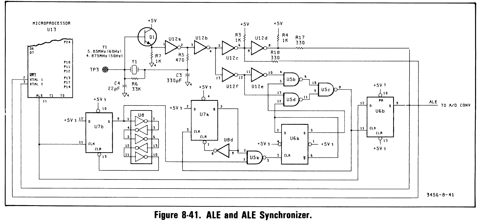
For 60 Hz operation a 5.85 MHz crystal is used, for 50 Hz operation a 4.875 MHz crystal is used. This is 97500⨉ the mains frequency.
[0]: In fact it's done by making sure the ADC sample time is whole multiples of the line frequency by default (integration time can be adjusted in multiples of the mains cycle time). Because of this, the 50 Hz models will give readings slightly slower than the 60 Hz models.
Cutting to the chase
To convert a unit between 50/60 Hz the appropriate crystal must be installed. Unfortunately neither of those frequencies are very standard, and getting custom cut crystals is harder than it used to be.
Some other experimenters have used multiples of the desired frequency and built divider circuits on the board to get the correct frequency. This is possible, but I couldn't find any of the easy multiples either.
Digi-Key offers a programming service for various ICs, including programmable oscillators. At the time of writing this there's no minimum order and the costs per IC are reasonable considering it's a manual operation.
I decided to use this service, and I chose an Epson SGR-8002DC-PTM oscillator. This is a 5 V DIP packaged oscillator with perfectly reasonable specifications though pretty poor stability. Other variants can be used, but options for 5 V capable chips aren't that great. To get the correct frequency I just entered "4.875 MHz" as the customer reference for that order position.
Installing it
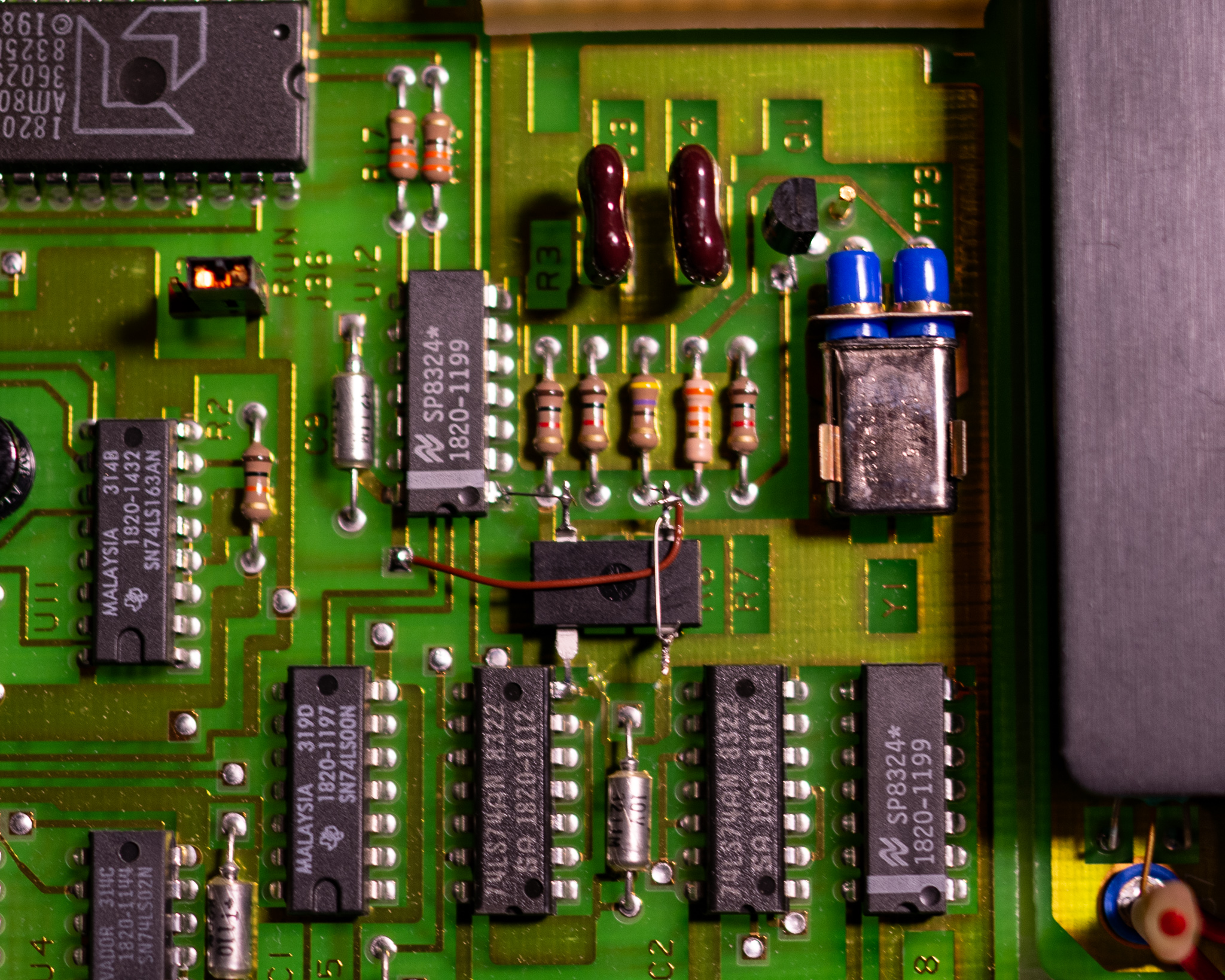
The A30 board is on the bottom of the unit, so remove the bottom cover and the inguard shield. The inguard logic boards are referenced to the voltmeter terminals instead of chassis; this means they are potentially hazardous if you're measuring high voltages. Both screws are Pozidrive 2 (don't use a Philips driver).
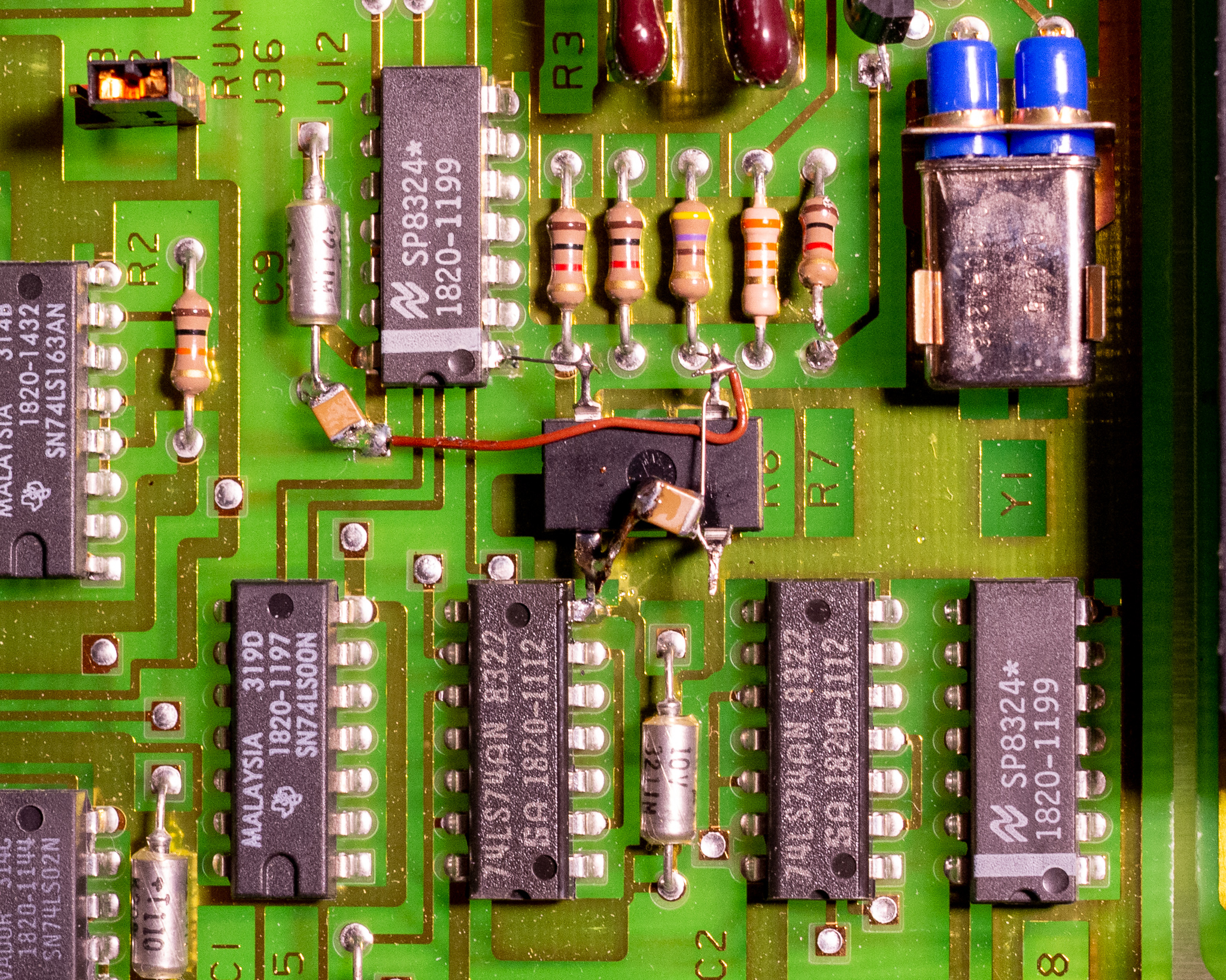
Referring to the schematic above, I decided to a minimum effort mod. I simply cut the emitter lead of Q1 to disconnect the original oscillator from U12:1. I also cut one end of R7 to reduce the loading on the oscillator output.
The oscillator was dead-bug installed with the ground lead connected to another IC, and some wire straps to complete the circuit. I added some 1210 10 µF X7R MLCC capacitors (see below for why). One is installed between the GND lead of C9 and near pin 14 on U12 to bypass this better, the other is across the oscillator pins.
After doing this I powered up the instrument and ran a self-test which passed a few times. I also left it powered up measuring a voltage reference, and it now gives completely stable readings.
This oscillator does not affect the ADC calibration, and no re-calibration is required.
Stability
While I didn't measure the performance in a highly rigorous manner, I do have a DIY 5 V voltage reference (unheated) that is quite stable and accurate. It's my primary transfer standard for voltage.
In order to check performance, I used this standard with the instruments in statistics mode and looked at the variance reading.
I initially didn't install additional bypass capacitors near U12 and the new oscillator, this gave a 1fV variance reading. The same reading on a stock 50 Hz unit was 0.12 fV, almost 10⨉ better.
I repeated the test with the low pass filters active on both units, and got similar results, suggesting the effect is not related to the frequency accuracy of the new oscillator. It could be caused by jitter, the oscillator is specified up to 250 ps p-p jitter. This is around 10⨉ higher than you might expect from a standard crystal.
There could also potentially be thermal effects going on, but I doubt it since the instruments are stacked inside a fairly stationary rack.
After installing bypass capacitors and removing R7 to reduce output loading I repeated the test and ended up with similar results. Looking at the min/max I'm seeing a variation of ±0.5 least significant digit (min/max is 1 digit apart), so this is definitely a very minor issue for my use.
I may return to do further measurements once I get some GPIB equipment in house.
It's also quite possible that I'm seeing e.g. a slightly oxidized front/rear selection switch, or some thermoelectric effect.
Other notes
One of my voltmeters broke shortly after I got it. This failure was in one of the Ohm mode ranges, and led to the meter switching back and forth between two ranges in auto range mode. The unit also gave a BIT error, though I forget which one specifically.
The issue was a quad comparator in the A20 Input Switching board that was used to switch several JFETs to change current ranges for Ω measurement. This comparator was just a LM339 in standard DIP packaging so it was easy to replace.
Unrelated, the standard digit display modules are still available to buy, while the ±1 indicator module is not in production. The unit I use the most has a fairly worn down display compared to the others (it's fine to use, but noticeably dimmer) — for now I'm just rotating the units around to equalise the wear.
According to the service manual you need 7⨉5082-7611, and 2 pcs 5082-7616 per unit. The 7611 is in production at the time of writing this, and the 7616 can be found NOS (though not very cheaply). If you wanted to you could also put in different colour displays for a unique look, though you'd probably want to replace the red window to get full brightness.