A Pole Mount PoE Radio Modem

This article documents a pole mounted dual band radio modem, suitable for use with 9600 baud data, 4800 baud PSK, 1200 baud AFSK, and voice.
Overview
The purpose of this system is to be a pole mounted Ethernet-powered dual band radio modem/voice gateway.
The core system comprises a PCA with two SA818S radio modules, an audio interface, and a Banana Pi-M2 Zero single board computer. Power is supplied via standard 30 W Power over Ethernet (PoE), and a GPS receiver is included for positioning and time-keeping.
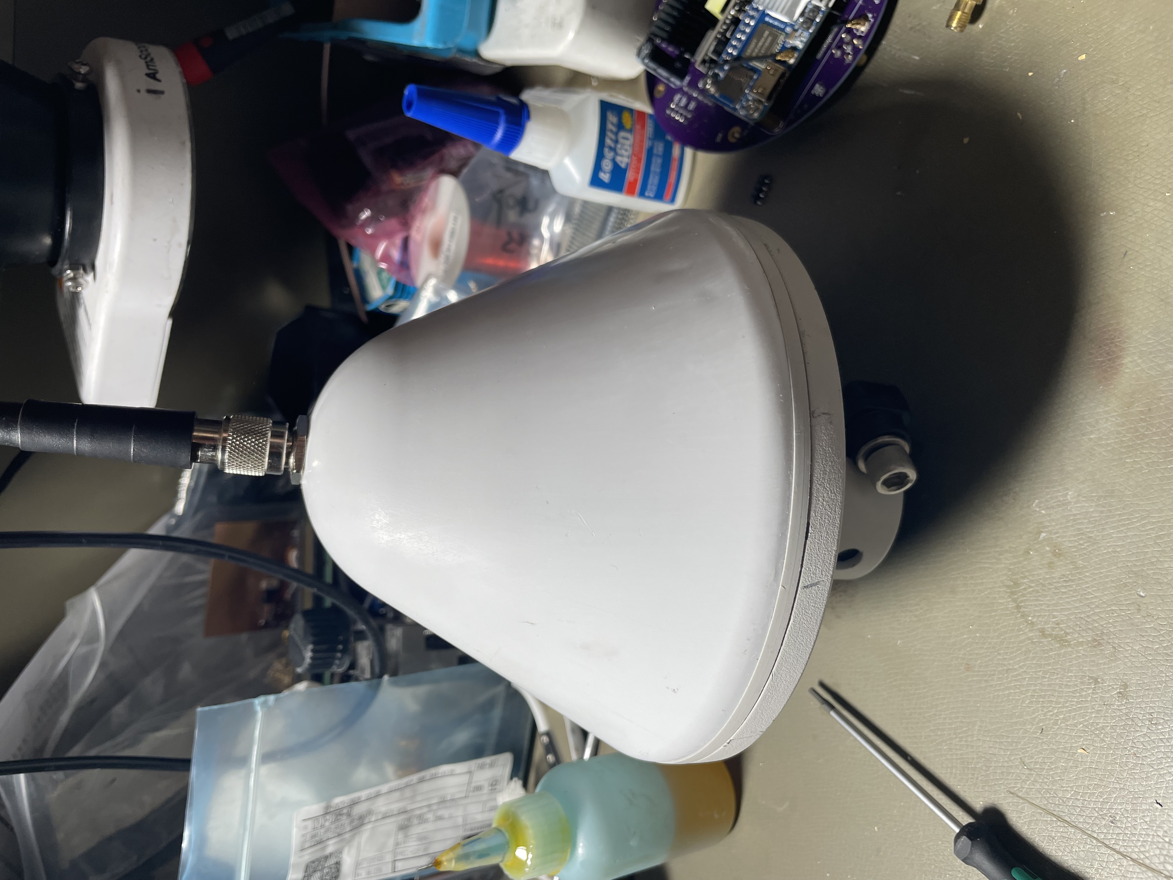
The final assembly is mounted inside a repurposed HP GPS receiver housing.
Table of Contents
Intended Use
The intended use case for the modem is as one of the following:
- APRS IGate/Digipeater
- Winlink Gateway
- 9600 baud seems feasible, 4800-PSK definitely is possible
- Cross band voice/D-Star repeater
- DMR DMO (simplex) may also be possible, but repeater access is not possible
- EchoLink gateway
- PoE+ powered (30 W)
- Ethernet or Wi-Fi (2.4 GHz) for connectivity
Implementation
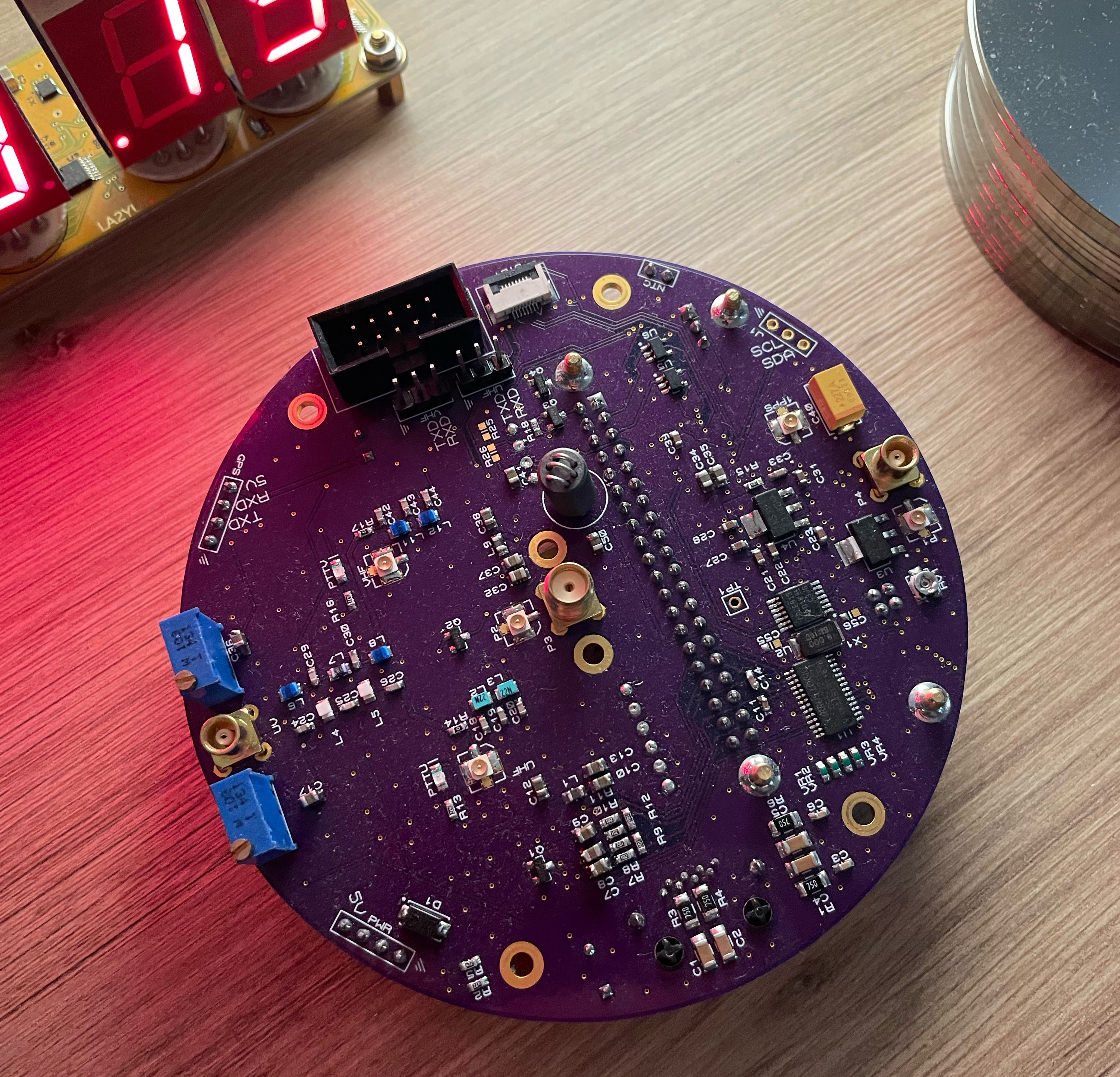
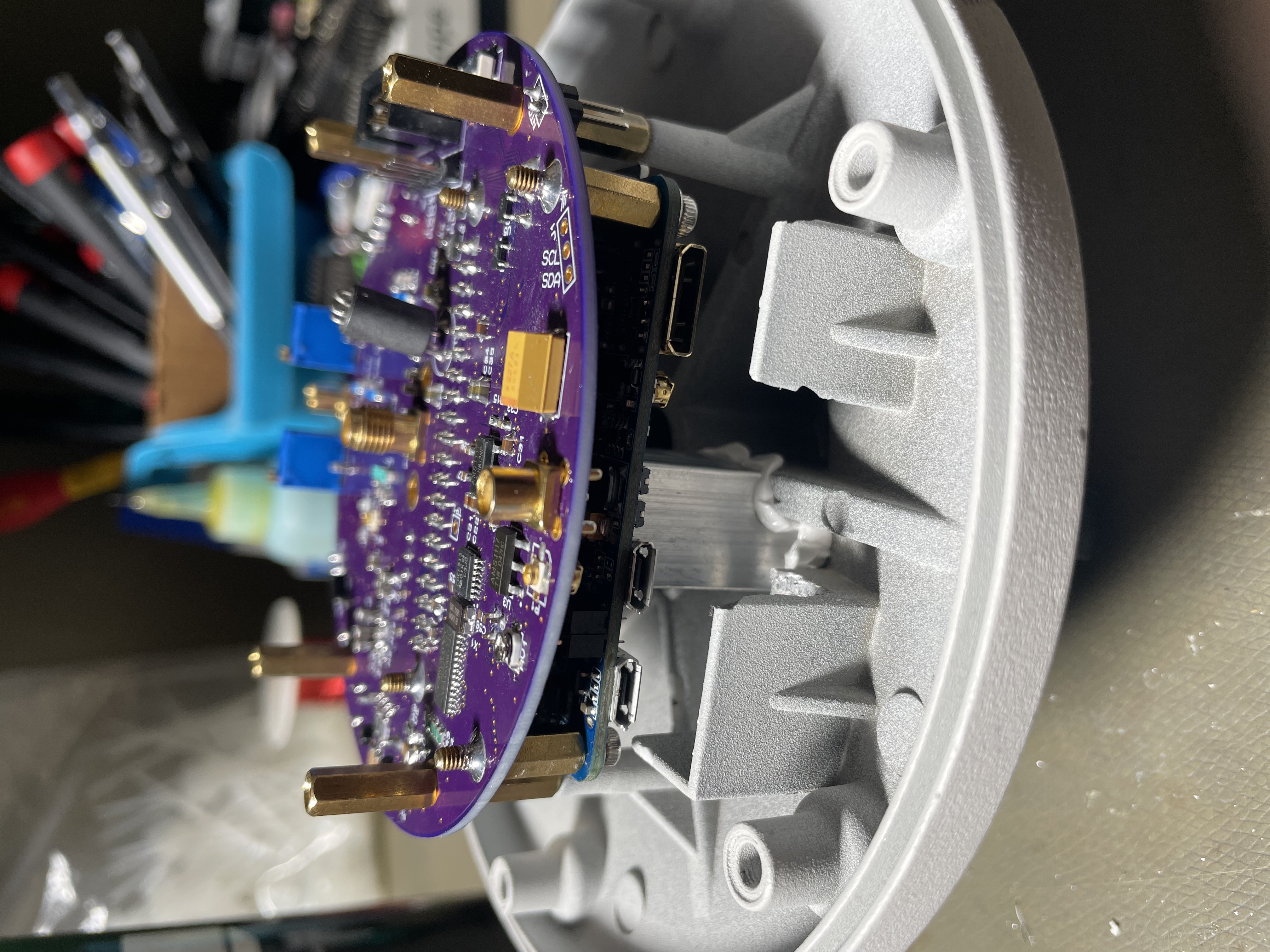
The PCA is round, which is what happens when rounded rectangle, but too much. The basic submodules are:
- Banana Pi M2-Zero
- RT5400 PoE module
- Audio Codec & Clock Generator
- 2⨉SA818S modules
- Diplexer to combine VHF/UHF signals to a single antenna
- GPS serial port + 1PPS
- STM32F0 Auxiliary MCU
- CPLD for signal routing

All this is implemented on a 4-layer PCB substrate.
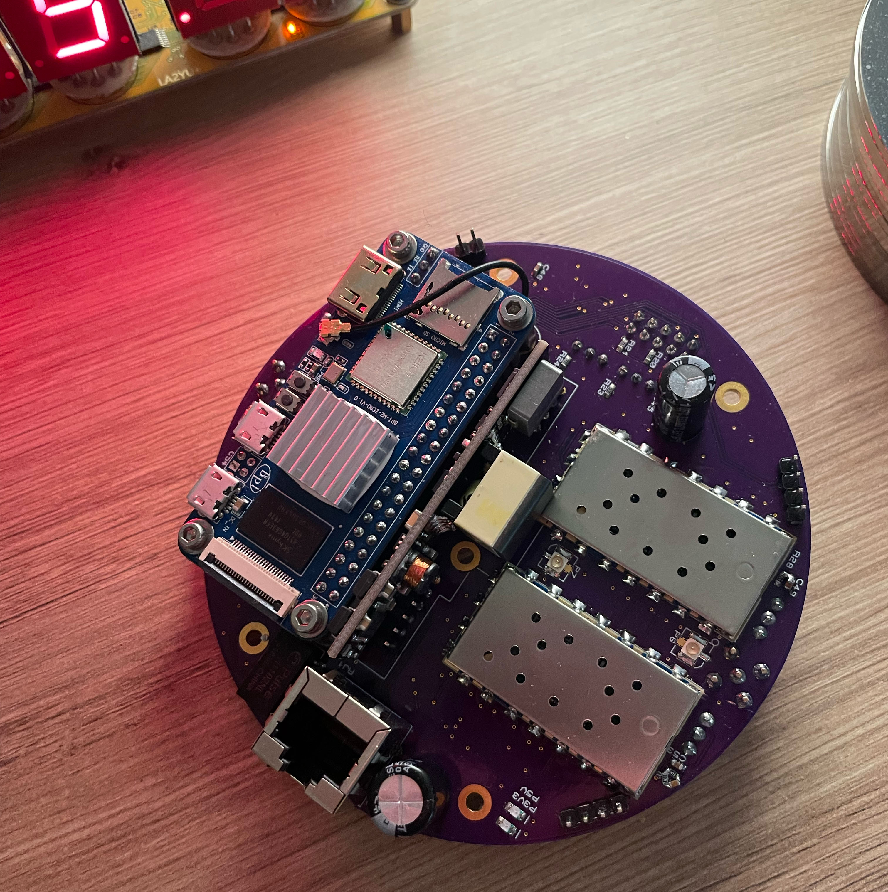
Banana Pi M2-Zero
This is a "clone" of a Raspberry Pi Zero (2) W, it is footprint compatible with this chip, but offers a faster 4 core AllWinner H3 processor, as well as an additional serial port and built in 100 Mbit⁄s Ethernet.
Ignoring the software support side, this is quite a good piece of hardware, and availability in 2022 is much better than the Raspberry Pi variant.
PoE Module
The PoE module takes power from the Ethernet interface (standard 802.3af) and generates a 5 V power supply for the system.
It's an R-Tone RT5400, and I have some notes below on it. It does seem to be a decent quality module!
Note that we do need a IEEE 802.3at (not af!) (aka. PoE+) injector for full power to be available, the 802.3af standard is limited to around 15 W, which does seem to be adequate for 1 TX at low power, but at full power I did find that my old 15 W injectors dropped out sometimes.
I chose to use a TP-Link TL-POE160S for my testing, it's basically the cheapest reputable PoE+ injector on the market.
Audio Codec
The audio codec is a CS4272 chip, which is a fairly old 24 bit stereo in/out I2S chip. This is as expected connected to the VHF & UHF radios transmit/receive audio lines.
In order to allow the use of digital modulations, the low frequency cutoff was set around 5 Hz, and the high frequency roll off is around 16 kHz (the radio has a lower bandwidth). The extended frequency range ensures very little added phase distortion in the likely frequency range (typically ~50-5000 Hz). As usual the codec is a ΔΣ type which does not require particularly tight analog filtering.
Some 20 turn potentiometers go in series with the TX signal paths to allow optimization of the TX levels, while for RX the dynamic range of the ADC means no level adjustment is required.
Clocking is done with a CDCE913 PLL generator, which also clocks the CPLD. This device is programmed over I2C from the BPi.
Unlike previous implementations I've made, I chose to use a straight codec rather than a DSP here, since it's primarily intended for data modes where pure flat audio is preferable anyway.
The downside to not using a DSP is that many software modems don't implement e.g. 1st order pre-emphasis corrections which can be used to extend the usable frequency range of an otherwise low pass filtered channel. I did however implement this functionality for the TX path, see the notes at the end.
Radio Modules & Diplexer
The SA818S modules are also discussed further down, these are 1 W FM transceivers intended for use in portable radios. Each radio is connected to the audio codec and CPLD.
The SA818S is 9600 baud capable with a slight pre-emphasis on TX, see the notes at the end for measurements.
The output of both radios includes a 5th order low pass filter, and a diplexer based on a design by KW4FB.
Antenna
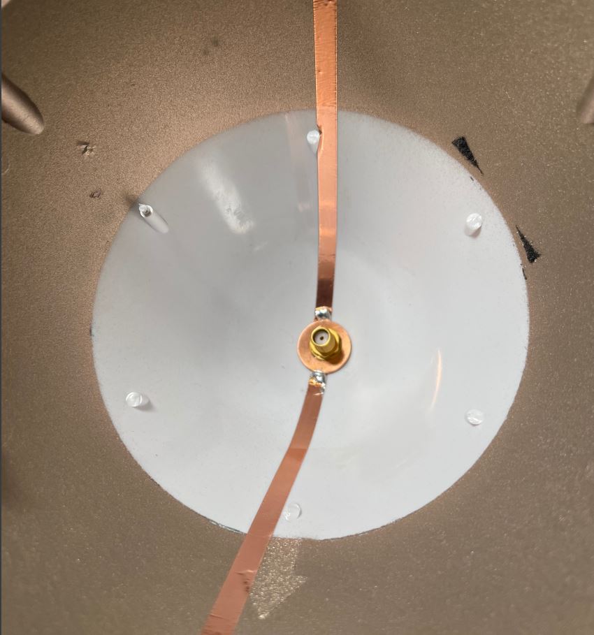
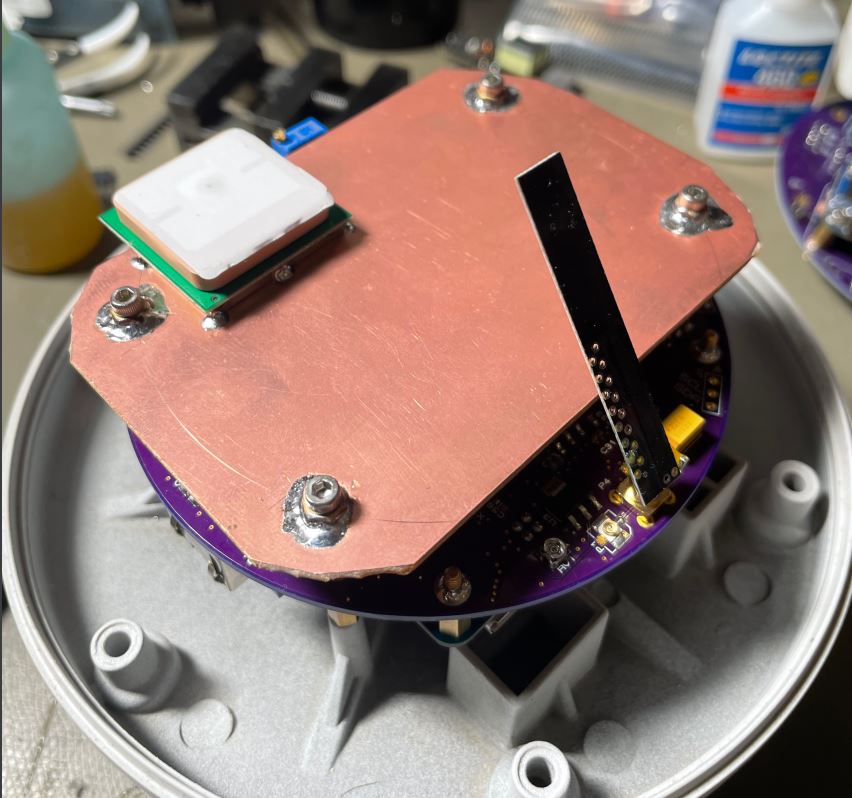
Technically it is possible to put the VHF/UHF antenna inside the radome, but the VHF efficiency would be very poor. I opted to install an RF connector in the tip of the radome, and use SMA antennas intended for hand held radios.
Since VHF antennas for hand held use require a ground plane, a copper washer was soldered to some thin copper tape, which then connects capacitively to the radome EMI shield. This shield is then connected to the aluminium base.
The Diamond SRH-36 was selected for this setup, it's available locally at a reasonable price and unlike most AliExpress dual band antennas, this one actually works. It's commonly used for VHF APRS trackers in my area, so it's fairly well proven.
For a more compact setup, a Diamond SRH-701 could be used, and for a more stealth setup an internal SRH805S could also be used, although this is quite inefficient.
The SMA feed-through is soldered to a copper washer on the outside as well, and this washer is epoxied to the radome. A small O-ring is placed between the connector and antenna to waterproof this junction.
GPS Module
The GPS is a very cheap but pretty decent module, it is the V.KEL VK2828U7G5LF, which has standard UART and 1PPS outputs. It's connected to one of the Pi serial ports, and the 1PPS is routed to a GPIO and used for time synchronisation using chrony and gpsd.
This is only an L1 GPS receiver, but it does support SBAS, and automatically found the EGNOS SBAS carrier and applied corrections.
The GPS receiver is soldered to a ground plane which also acts as a shielding plate between the antennas and radio/processor stuff.
CPLD
The CPLD is a Max II EPM240 device which sits between all the BPi I/O and the rest of the hardware, allowing full pin flexibility with the exception of I2C.
It is also provided with two clocks from the audio clock generator.
Auxiliary MCU
The STM32F0 MCU is not used at present, but could in principle be used instead of the BPi for very simple applications where e.g. only cross band repeat would be required. It will likely be used to implement features like TX timeout, and chassis temperature monitoring.
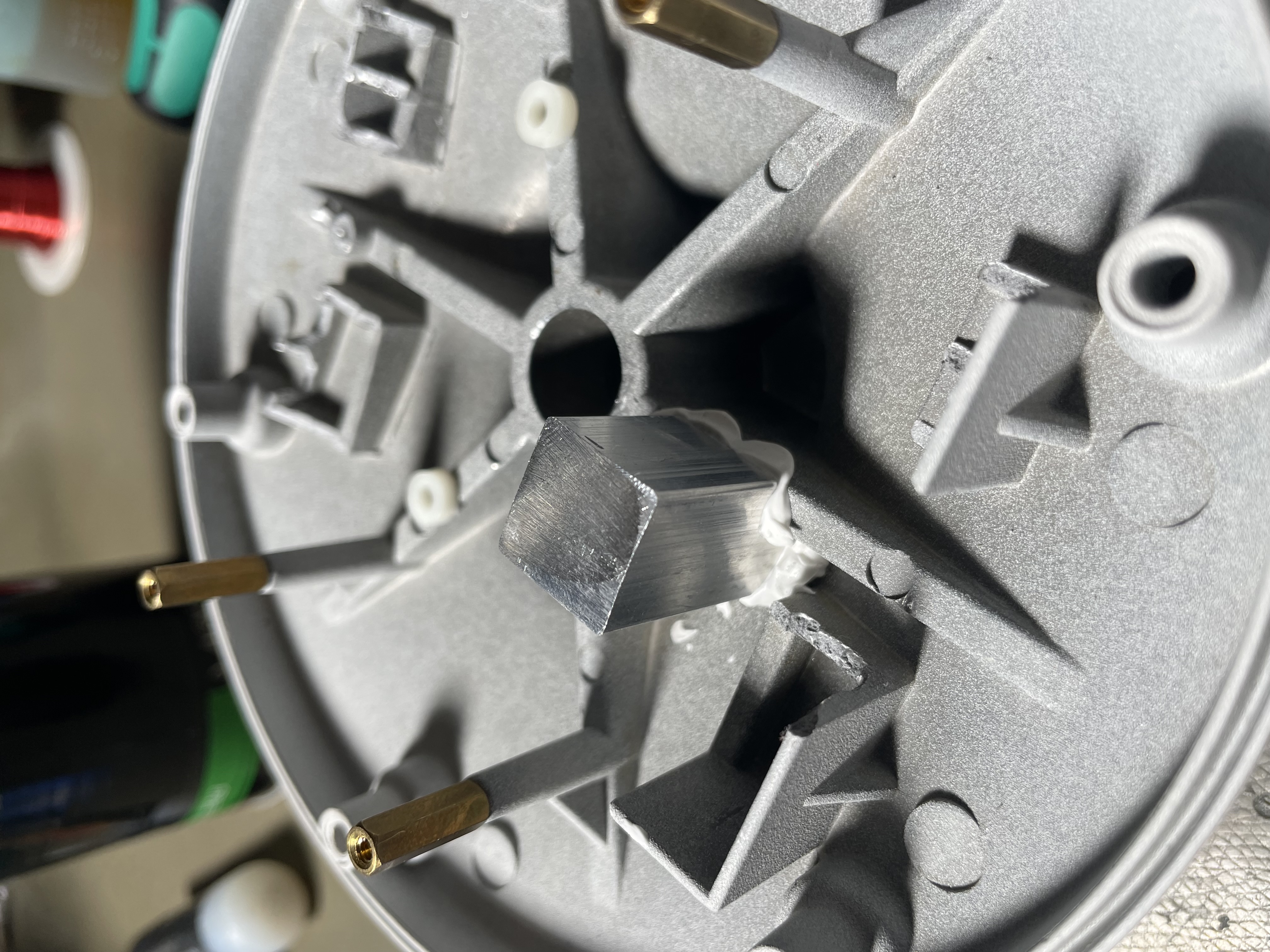
Thermal Interface
A set of 15x15 mm aluminium bar pieces were acquired to implement some thermal posts. I elected to cool both the Pi and radio modules to chassis with this method.
Implementation Notes
Banana Pi M2-Zero Audio
Getting I2S audio in (the unfortunately named) slave mode working on this hardware (AllWinner H3) was challenging since there is little clear documentation on how to do it.
I managed to piece together an overlay to enable this, and it seems to work quite well except for the channels being swapped. This was fixed in the codec.
My choice of codec also meant that I had to make some manuals scripts to configure it, since there's no kernel driver available (and getting that to work would be even harder).
See my GitHub repo: https://github.com/longview/BPi-M2Zero
Wi-Fi
I couldn't get the Wi-Fi to connect initially, I noted a fix here: https://github.com/longview/BPi-M2Zero
It seems to have been related to the selection of security modes, so might be possible to use nmtui to set this up manually as well, but the defaults definitely did not work.
I selected a fairly generic AliExpress U.FL PCB antenna for the Wi-Fi, this antenna actually works quite well, and is spot on resonant at 2.41 GHz. The antennas were modified by soldering them directly into a MCX male connector at an angle and securing with epoxy resin. Removing the original adhesive strip was a nightmare though.
This was practical since I included two unused RF connectors on the board intended for use as a feed-through, with U.FL connectors on top and bottom + a through hole connector in the middle and to one side of the board. I then simply ran a U.FL patch cable from the BPi to the appropriate feed-through.
While Wi-Fi is a secondary interface it's still nice to have it working, in case the device is installed somewhere where Ethernet internet is not available. (Obviously we still need Ethernet for power, but you could just use a bare PoE adapter with no actual Ethernet signalling present)
The Wi-Fi interface will typically get a higher metric score, meaning it will not be used as long as Ethernet is present. This can be seen through the "route" command with no arguments.
RT5400 PoE Module
The RT5400 PoE module is a convenient way to get a working PoE setup. It is a "30" W module, with the 5 V output variant providing around 4 A max. The module just requires a suitable ethernet transformer and hookup.
The output is completely happy with a 1000 µF decoupling capacitor, the manufacturers drawings indicate up to 10 mF of output capacitance is acceptable. This is quite high, so they likely have a slow start/current limit mode built in.
For the BPi's 100 Mbit Ethernet a Pulse H1102NL is used, which it turns out is not actually a PoE rated device. A Bourns SM13126PEL might be a better pin compatible choice, but the Pulse transformer does appear to work.
I note two things about this module: the drawings show the wrong polarity for the optional input filter capacitor, as I discovered when the system wasn't working and the capacitor started to get warm and bulge. I caught it before it popped at least.
Second: the output of this module seems to use a synchronous rectifier? In any case, the output of the module is basically shorted when the input power is off. This means that you can't simply hook up an external 5 V supply to the same rail, to do this you'd need to add some series diodes or another switching solution.
SA818S vs. SA818
The SA818S and SA818 are analog radio modules manufactures by niceRF, typically available through their AliExpress store for around $10 a piece. They mostly manufacture VHF and UHF variants.
These two variants are nominally similar, though the SA818S is a newer and better module.
The measured receiver 6 dB RF bandwidth is around 18 kHz in the wide mode, and 10 kHz in narrow mode. There is also around a 2 dB improvement to sensitivity in narrow receiver mode, with a 1 kHz tone @ 2.2 kHz deviation for 12 dB SINAD (CCITT, radio filters off). However, the distortion performance is worse in narrow mode (as expected), so there is a tradeoff here.
A serial port configuration script is available here: https://github.com/0x9900/SA818.
One thing I discovered is that the older SA818 variant does not appear to implement the filter switching properly, and this module is limited to 300-~2700 Hz bandwidth. It has a very sharp high pass, completely attenuating at 200 Hz.
The SA818S variant however does support disabling both high, low, and pre-emphasis filters. In this mode both transmit and receive are almost completely flat, with a usable bandwidth of around 10-4000 Hz, and no sharp rolloff at either end.
Because of this I had to swap out all my UHF modules to achieve full audio bandwidth on both bands, since I originally installed the older model, not realising this difference.
Measured Frequency Response
Measurements were performed for both transmit and receive on both bands. I performed tests normalised to 2 kHz deviation in Wide bandwidth at 1 kHz signal, measurements in dB relative voltage (i.e. –6 dB = halved deviation/voltage).
Measurements were performed using a Stabilock 4015. The SA818S reported firmware version "V1.1".
| Frequency | All Off | LP & HP Off, Emph On | LP & HP On, Emph Off |
| 30 | –2.7 | +9.2 | <–40 |
| 50 | –1.1 | +10.6 | <–40 |
| 100 | –0.2 | +11.1 | <–40 |
| 200 | 0 | +10.7 | <–40 |
| 250 | 0 | +10.3 | <–40 |
| 300 | +0.2 | +9.8 | –1.1 |
| 500 | +0.2 | +6 | +0.1 |
| 1000 | 0 | 0 | 0 |
| 2000 | –0.4 | –6.4 | –0.1 |
| 3000 | –1 | –10.5 | –0.8 |
| 4000 | –1.2 | –13.4 | –11.2 |
| 5000 | –1.5 | –15.5 | –28 |
| 6000 | –4.6 | –20.8 | <–40 |
The case of LP/HP & Emphasis on is just the sum of attenuations of the two rightmost columns.
We can see that the SA818S with all filters off can receive approximately 30-5500 Hz (–3 dB), an excellent showing for the cost. I also note that enabling filters had an effect on the receiver levels.
And for transmit the range is slightly less, approximately 50-4500 or so (likely just about acceptable for 9600 FSK).
| Frequency | All Off | LP & HP Off, Emph On | LP & HP On, Emph Off |
| 30 | –6.2 | –22 | <–40 |
| 50 | –2.8 | –18.2 | <–40 |
| 100 | –0.7 | –15.1 | <–40 |
| 200 | –0.1 | –11.9 | <–40 |
| 250 | 0 | –10.6 | <–40 |
| 300 | 0 | –9.4 | –1.3 |
| 500 | 0 | –5.6 | 0 |
| 1000 | 0 | 0 | 0 |
| 2000 | 0 | +5.2 | 0 |
| 3000 | –0.4 | +5.9 | –0.6 |
| 4000 | –1.8 | +5.8 | –12.2 |
| 5000 | –4.2 | +5.5 | –30 |
| 6000 | –7.2 | +5 | <–40 |
The responses are also plotted for your convenience here:


The UHF SA818S has not been measured at this time, it is assumed to be similar.
9600 Baud TX Waveform
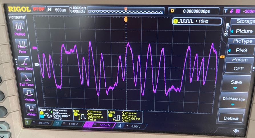
I used direwolf's test signal generator to make a 9600 baud signal and transmitted it to the 4015 test receiver (a highly linear/wide band receiver). The result is a reasonably good waveform, but it's clearly lacking some high frequency response: the low frequency transitions are close to 2 Vp-p, while the highest frequencies only reach around around 400 mVp-p.
We can see that an optimal slicer-level would likely correctly decode this signal, but it could be better.
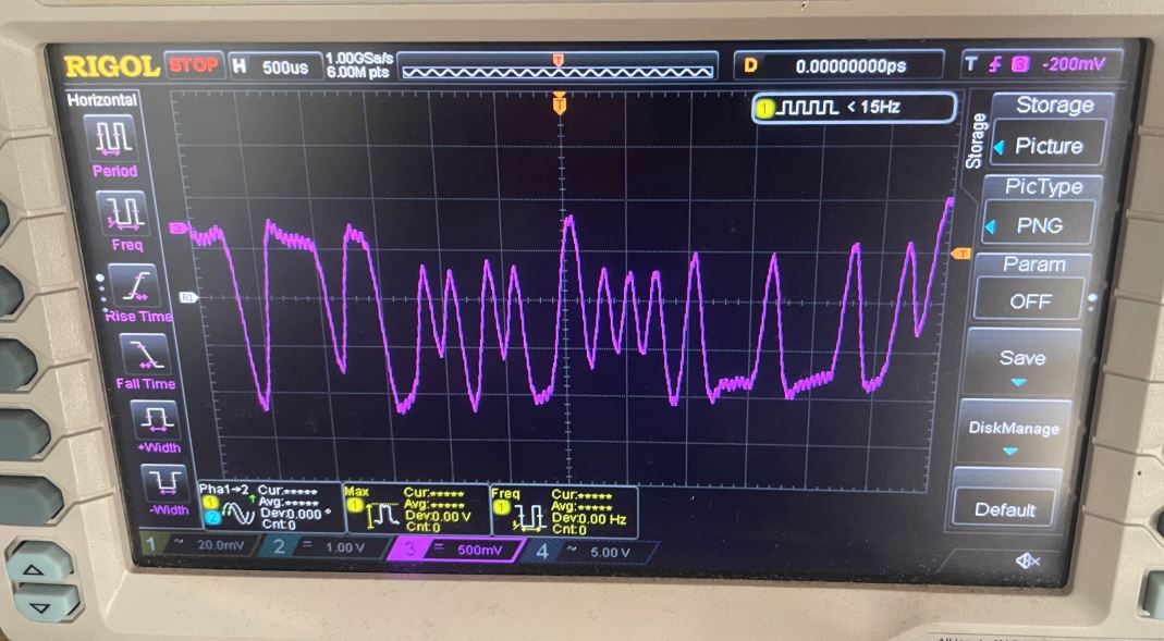
By adding a slight hardware pre-emphasis to the transmitter audio we can improve things slightly, bumping the higher frequencies up to around 1 Vp-p.
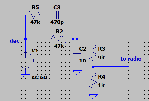
While not perfect, this is an improvement.
We can be a bit more assertive, and change R5/C3 to 10 kΩ/1 nF, increasing the amplitude to around 1.5 Vp-p:
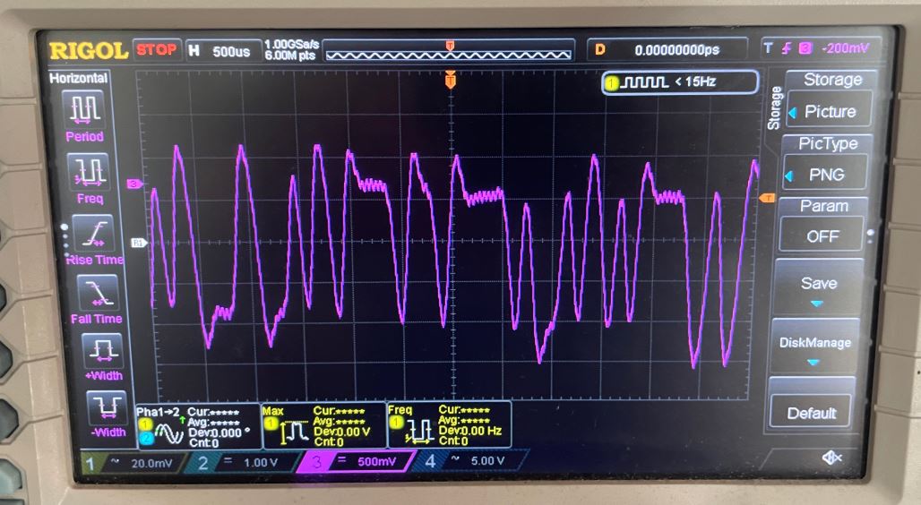
Giving the following schematic:
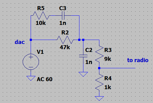
With this network the response would seem to be adequate! It's a bit peaky, so the exact right crossover frequency was not hit, but it seems to be good enough, and it doesn't require any uncommon component values.
If I do a respin I will likely include an active amplifier implementation of this network for both TX and RX.