Improving the Wide Band RoF System

The Wide Band RoF System works quite well, but some practical issues were identified after almost a year in operation.
Power & Heat
The primary issue identified is the highly inefficient power system, the system was originally intended to use an 8 V bus with local 5 V regulation. However, this ended up being implemented as a 15 V bus with the same local 5 V regulation. This was done since the PIN attenuator design requires around 12-15 V to be available, so in the interest of getting the project done I wired it for direct 15 V supply.
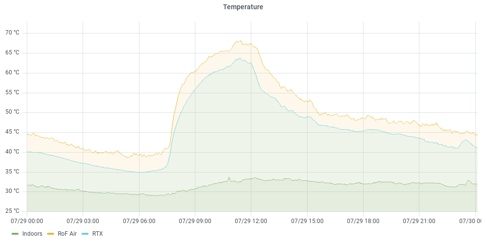
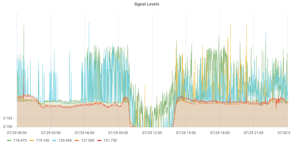
Above are some Grafana plot showing the decrease in RF levels when the in-box air temperature exceeds around 65 °C. There is clearly a correlation (this was observed at a few occasions), and something has to be done.
Because of the linear regulation and high input voltage the efficiency of the system is extremely poor, ⅔ of the power consumed is wasted. By using switch mode 7-8 V regulators for the Combiner/Amplifier assemblies approximately ½ of the wasted power can be eliminated.
The selected implementation is to build a backplane PCB that provides a separate DC/DC module for each Combiner/Amplifier, this can be adjusted to provide a suitable supply voltage in the 7-8 V range. This backplane board also provides buffering of the attenuator control signals to reduce loading on the driver.
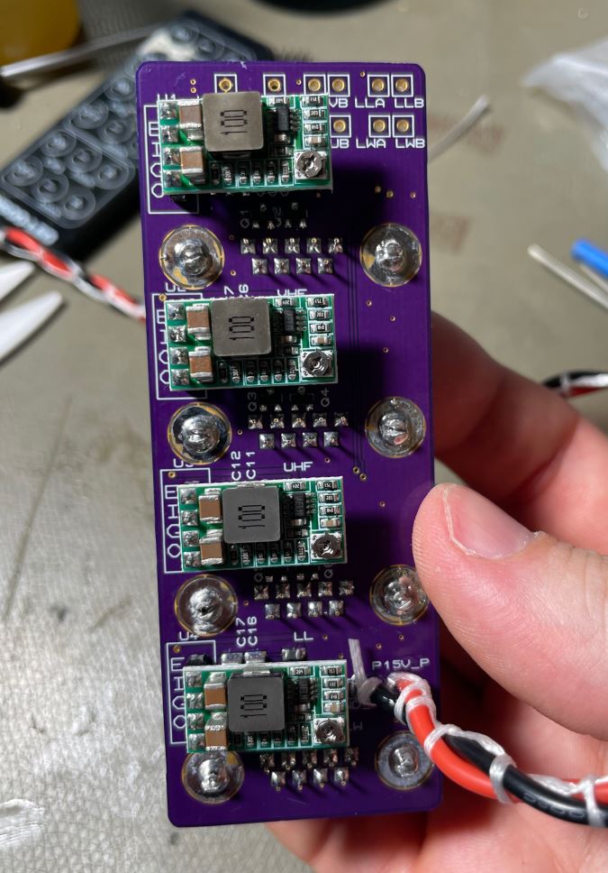
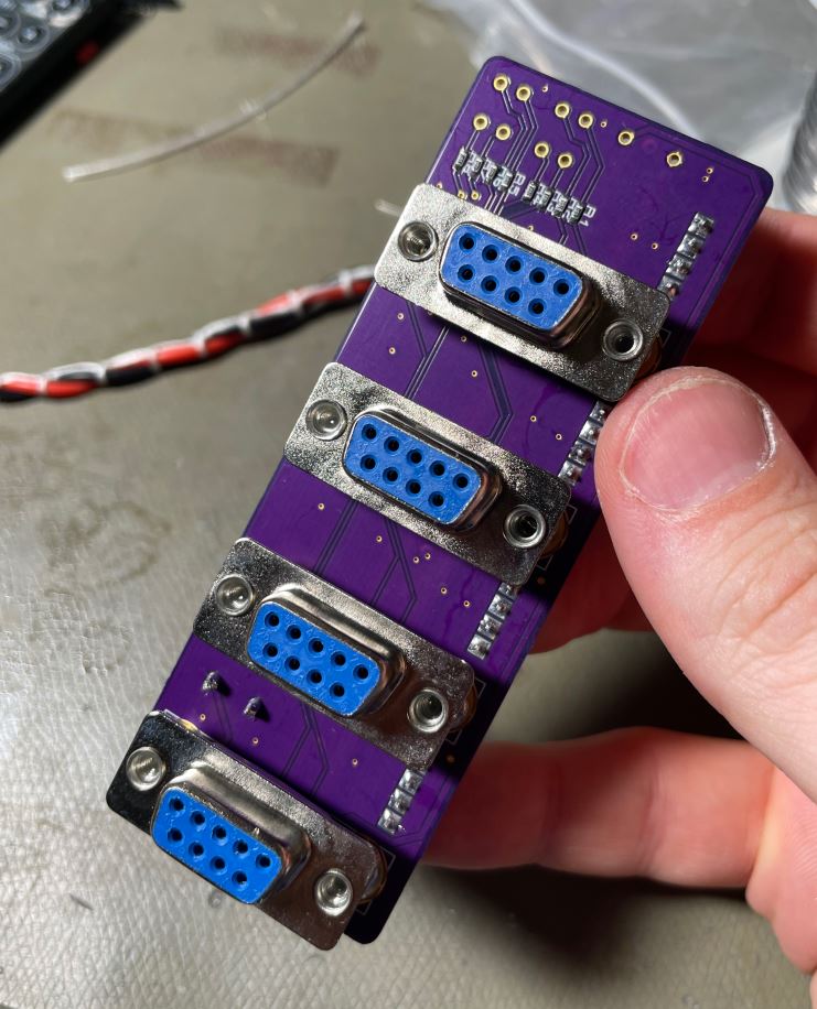
Since the DC/DC converters are on the backplane, they have no notable effect on system noise levels. The Combiner/Amplifier assemblies use very high quality filtered D-Sub connectors which effectively eliminate basically any conducted high frequency noise. Noise was the primary reason for not including a DC/DC converter inside each assembly.
Fiddly Controls
A secondary issue is that the channel gain control is a set of manual trimmer potentiometers, which requires a lot of iteration when aligning the channel gains if changes are made.
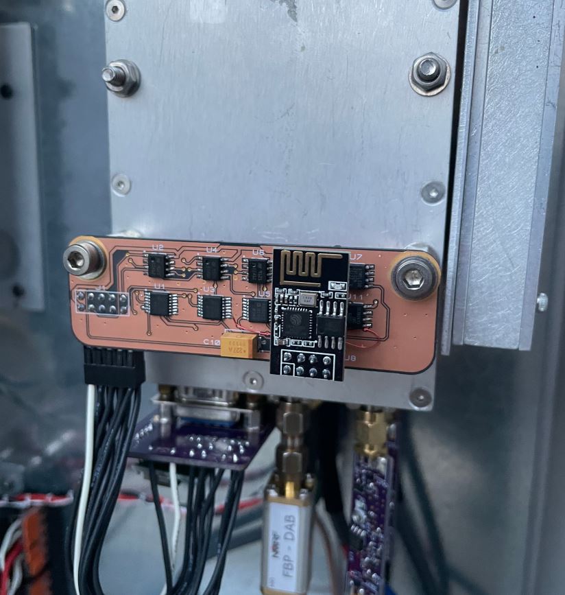
To resolve this, a replacement PCA was made that eliminates the manual gain control system, replacing it with a ESP-01 Wi-Fi microcontroller module that controls 8⨉ DAC channels with associated amplifiers.
This gain control PCA is installed instead of the manual control panel, and a network interface is implemented allowing remote control of the gains through a browser. A local flash-chip was also included to allow local storage of the set points.
Thermal Monitoring
I also stuck an ESP-01 + DHT-22 temperature/humidity monitoring device in the box (and some other places). This let me determine the internal air temperature and humidity of the enclosure, as well as calculation of water content and dew points.
A future upgrade will likely be an improved thermal monitoring system for use in various locations, with a set of NTC thermistor inputs suitable for chassis temperature monitoring of the various assemblies.
Overload Gating
A basic in-line overload gate was added to the VHF and UHF receiver antennas that cover ham radio bands. This simply consists of a power detector, an RF switch, and a comparator which disconnects the RF switch when the power level exceeds a threshold.
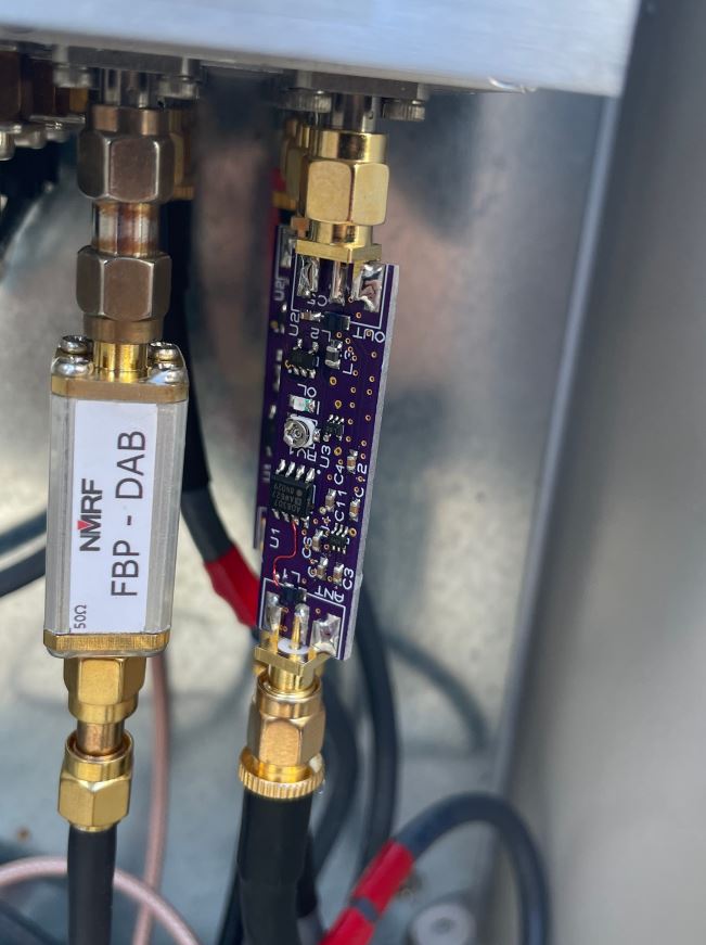
The design uses an AD8307 log detector for the power monitoring, and a HWS408 SPDT RF switch for the limiting. This gives around 30-40 dB isolation in the off-state, which is sufficient to avoid interfering with other bands. It's powered by the bias-tee, and also passes the bias power along to the antenna.
The gate levels were set to block the RF when a handheld 1 W radio was keyed up near the antennas. Losses and out of band noise isn't super critical in this use case, since it's operating on amplified signals, and the next stage has input filtering.