More HP/Symmetricom/Microsemi 58534A-H01 pictures
I bought some more 58534A-H01 receivers and found that these receivers were of the older type I had seen low resolution pictures of before.
The units I received were clearly marked as the -H01 which I believed was the newer PCB revision. However, these units were not marked with the additional revision stickers that my new in box unit had.
These units both had the cable cut at the base, I don't know why people do this, but since this was clearly shown in the eBay listing I knew what I was getting. These were a fair bit cheaper than the new in box unit at least.
The older variant PCBs and antenna are shown in detail below. The only other notable change was that the original radome had a metallic gold coloured spray coating applied up to the height of the antenna PCB. This was not present on the new in box variant with the integrated design.
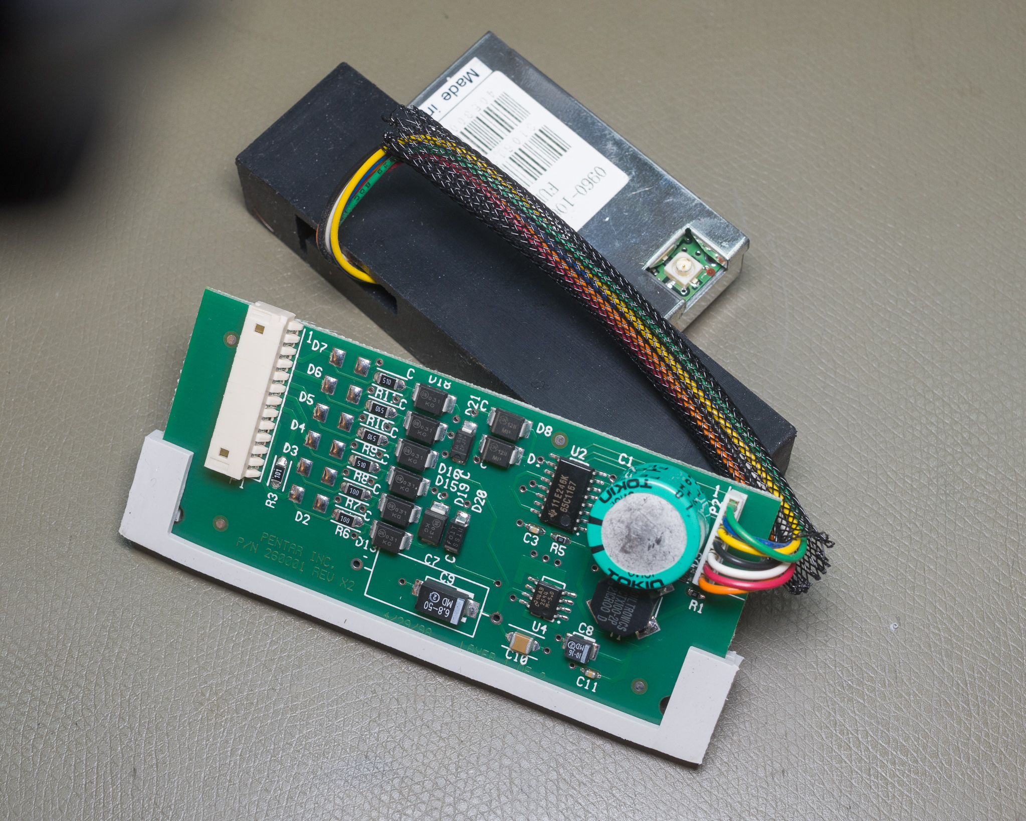
PCBs, GPS
The connector to the left connects to the external cable.
The PCBs were as suspected held in rubber supports originally. A single thin piece is used for the I/O board, while a thick piece is used to hold the original GPS receiver. This receiver is far larger than the one for the last revision.
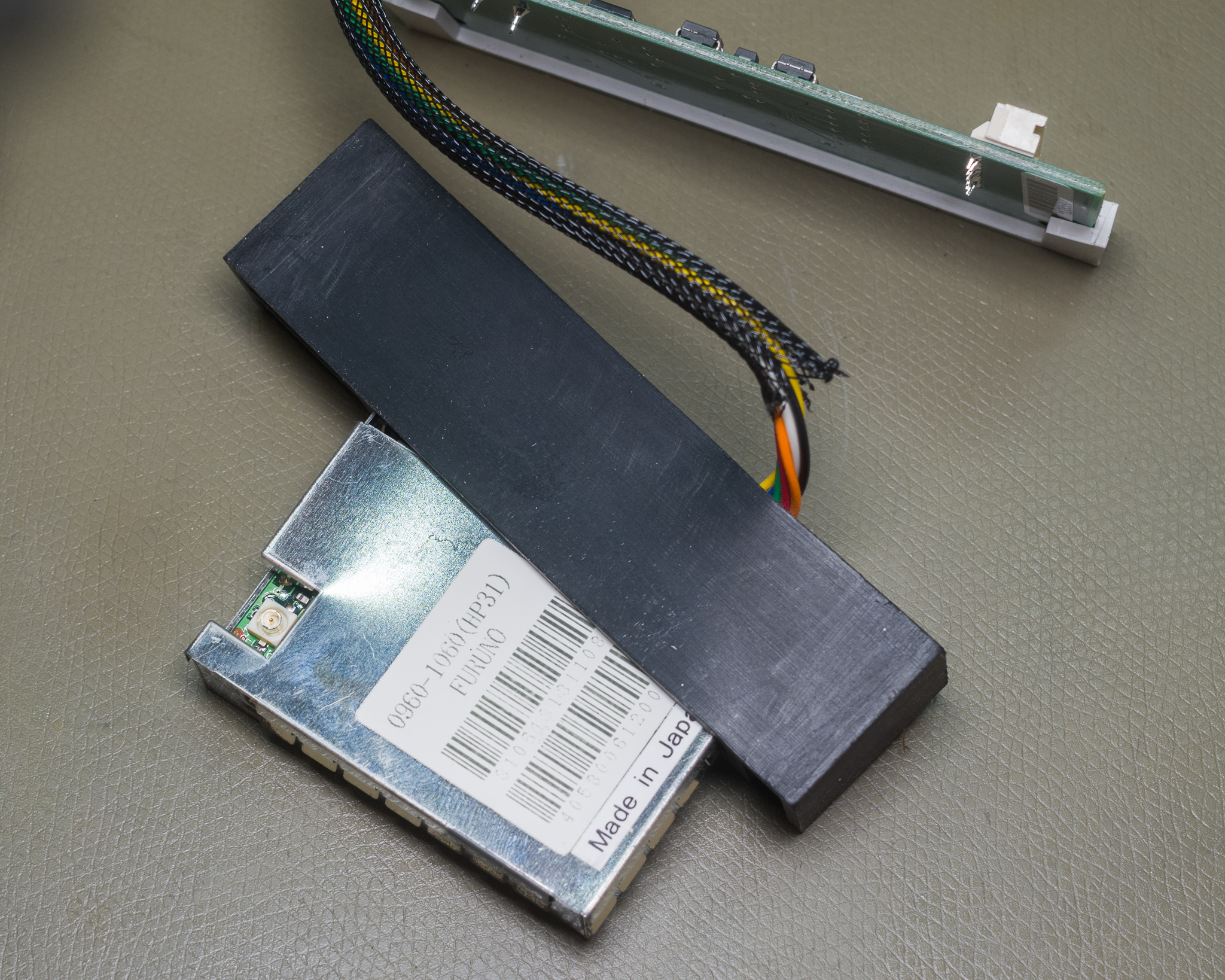
The GPS is labeled "0960-1060(HP31)". The connector is a bit larger than the now common U.FL connector, but seems to be otherwise identical.
Antenna
The antenna board was permanently fixed to the plastic pegs in the radome, but had some support from these large foam pads.
The support seems to be largely emotional since several of the pegs had broken during transit and this board largely fell out when I opened the radome.
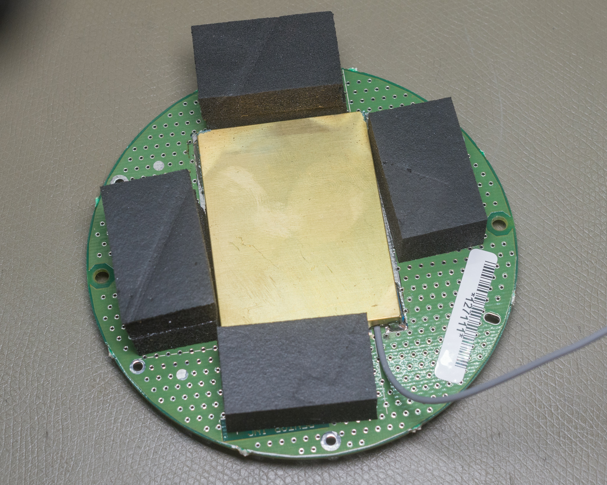
It looks like the same can and circuitry was used for this older version too.
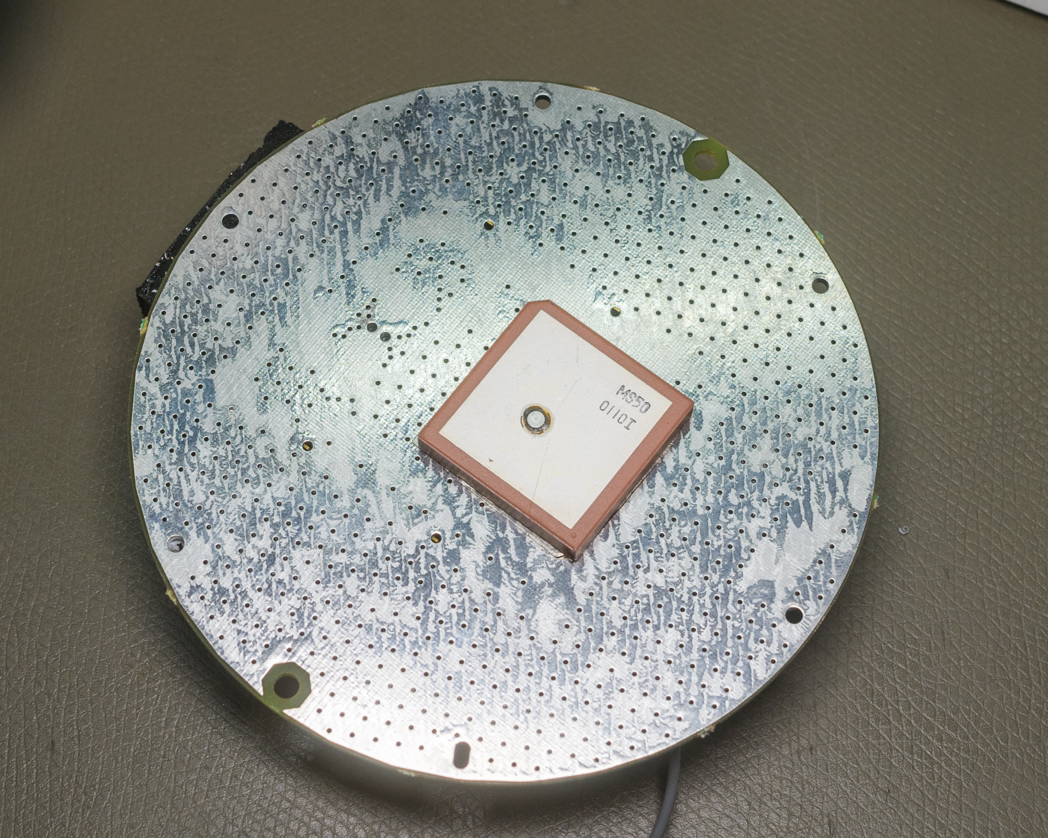
The same antenna as before. Identifying the make is probably near impossible unless someone happens to recognise it.
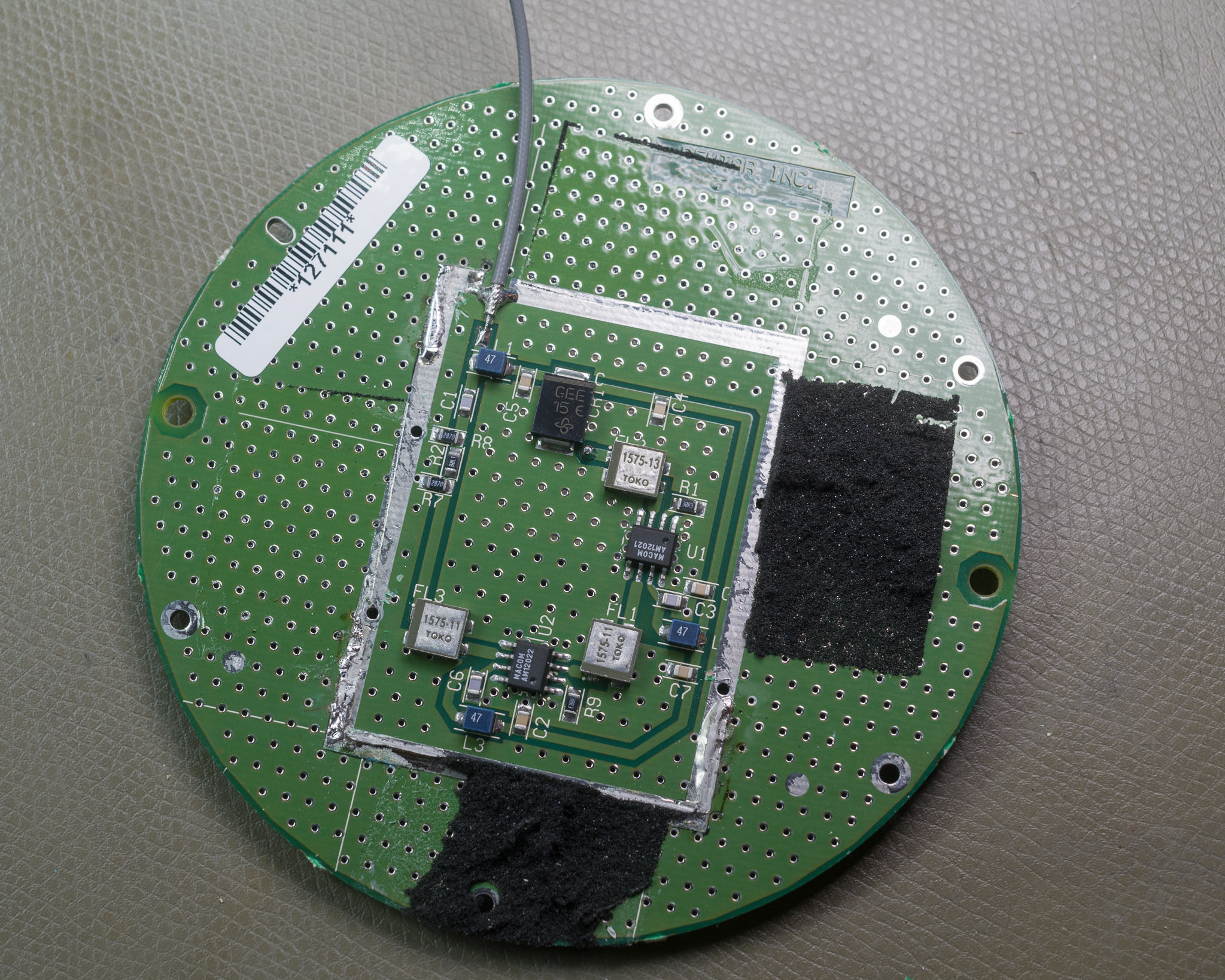
I removed the can this time, to show the insides.
The antenna connect right next to the large TVS diode, and goes through what Toko called a "Chip Dielectric Filter".
A 1575-13 is used for the first stage, I believe this is a TDF2A-1575B-13, a low loss (1 dB) but poor rejection filter (7 dB at +-140 MHz). The other stages are probably TDF2A-1575B-11 which has a much higher insertion loss at 5 dB but also around 22 dB side band rejection at 50 MHz offset. No curves were available in the catalogs I found.
The amplifier are both MAAM12022 by M/A-COM, no data sheet was immediately available but it's listed in app note M540 as a GaAs MMIC specifically for GPS receivers with 14 dB gain and 1.85 dB noise figure.
With 28 dB total gain and 10 dB insertion loss the total gain is around 18 dB, subtracting around 3dB for the output attenuator giving a 15 dB gain amplifier with a noise figure of around 2.85 dB. Antenna gain is unknown but given the large size it's probably around 0dBi.
Bias is almost certainly 5 V, the amplifier is 3-5 V compatible.
My guess is they chose this somewhat mediocre (by modern standards) MMIC for it's low power consumption compared to higher performance variants.