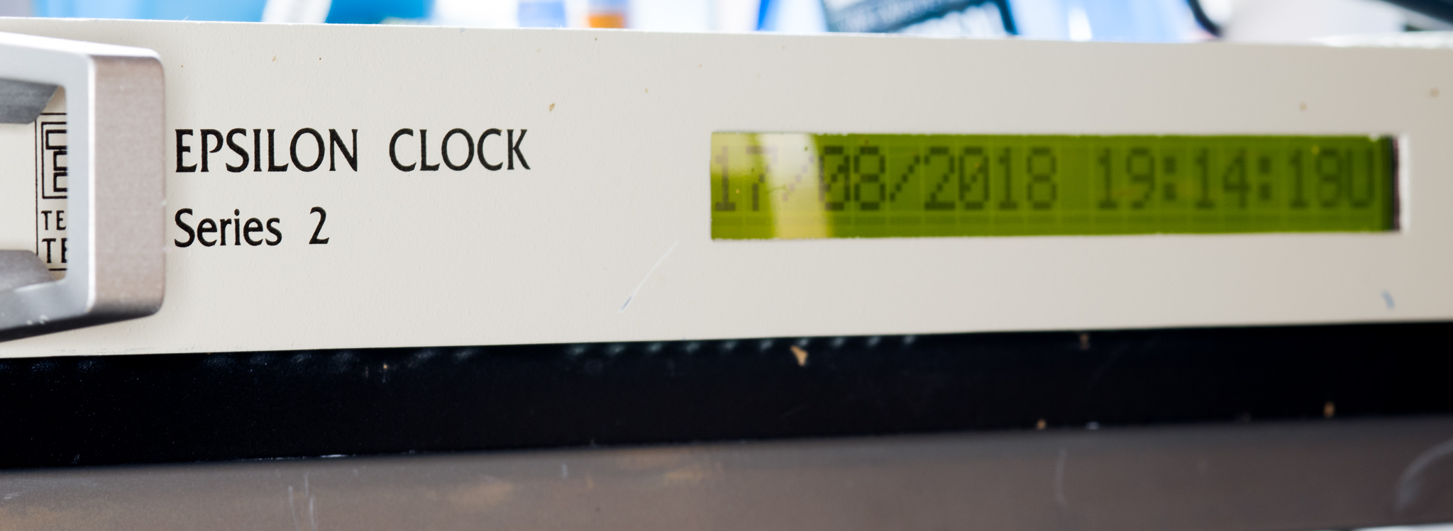
Spectracom Epsilon Clock EC2S, Overview and Configuration
The Spectracom Epsilon Clock EC2S and similar devices are fairly high end GPS clocks/timing receivers.
I've spent a few days with one and I wrote a utility to program the device that is available for download.
Table of Contents
The clock is available in various configurations, but most units will follow some basic rules:
- May say Tekelec/Temex or Spectracom on the front, it seems they updated the name in 2008 (i.e. were acquired)
- My units are marked as Made In France by TEKELEC SYSTEMES
- It seems Temex acquired Tekelec in 2005
- Temex Sync (presumably the timing division of Temex) later merged with Spectracom in August 2007
- Spectracom was then acquired by Orolia in September 2007, though the Spectracom brand stayed in use for several years
- GPS input (STANAG HAVE QUICK is most likely a pretty rare option)
- OCXO, either High Performance or Standard
- Rubidium was an option, but most likely not very common
- 1⨉1PPS output
- 4⨉10 MHz output
- Other frequencies are possible but most likely very uncommon
- Either no option boards or a choice of various types like additional frequency drivers, additional 1PPS outputs, IRIG.B, STANAG, etc.
- 120/230 V input
- 24 V input (backup)
- 48 V is an option
- Mini-DIN female, 7 pin on unit
- Pin 1,2,3,4 = VDC
- Pin 5,6,7 = Ground
- To figure out which one you have the easiest way is to look at the DC/DC converters, they're labeled with nominal input voltages.
- Antenna port on a TNC plug with 5 V bias
- Alarm output on twinaxial BNC
- TOD serial output
- Mini-DIN female, 6 pin on unit
- RS-232 levels
- RS-232 port
- Mini-DIN female, 8 pin on unit
In Use
The device will display a TOD on the display along with a source indicator, other status information is via two LEDs.
Depending on settings a 10 MHz output will immediately be available, or it will be enabled automatically once lock is achieved.
The unit will indicate a fault for a minimum of 20 minutes (1 hour for Rubidium), this seems to be hard coded and not based on any temperature sensing.
Frequency error when locked was very good, essentially identical to my Lucent RFTG setup, and I was unable to measure a frequency error at all but some phase shifting was seen on a scope. This was likely due to the Epsilon clock not being fully stabilized yet.
The unit is fairly open for modification, with a lot of spare room, there are up to three removable square panels that are replaced with additional connectors when options are fitted.
The GPS input is very lossy, because of this I recommend a high gain GPS antenna (25dB+). My normal 15 dB antenna with 10m of RG58 resulted in very poor performance. (The very old GPS receivers don't help here either).
Disassembly
For the love of god, get a Pozidriv 1 driver if you want to take it apart, the screws are NOT Philips.
Once you have the correct screwdriver, take out the screws on the top and remove the lid.
If yours isn't new in box, shake it around a bit to remove all the dead flies from it, it seems they like the heat but can't get out once they're in there. Most of them end up inside the power supply.
Notes on the internals
The internals are nicely laid out and assembled very professionally.
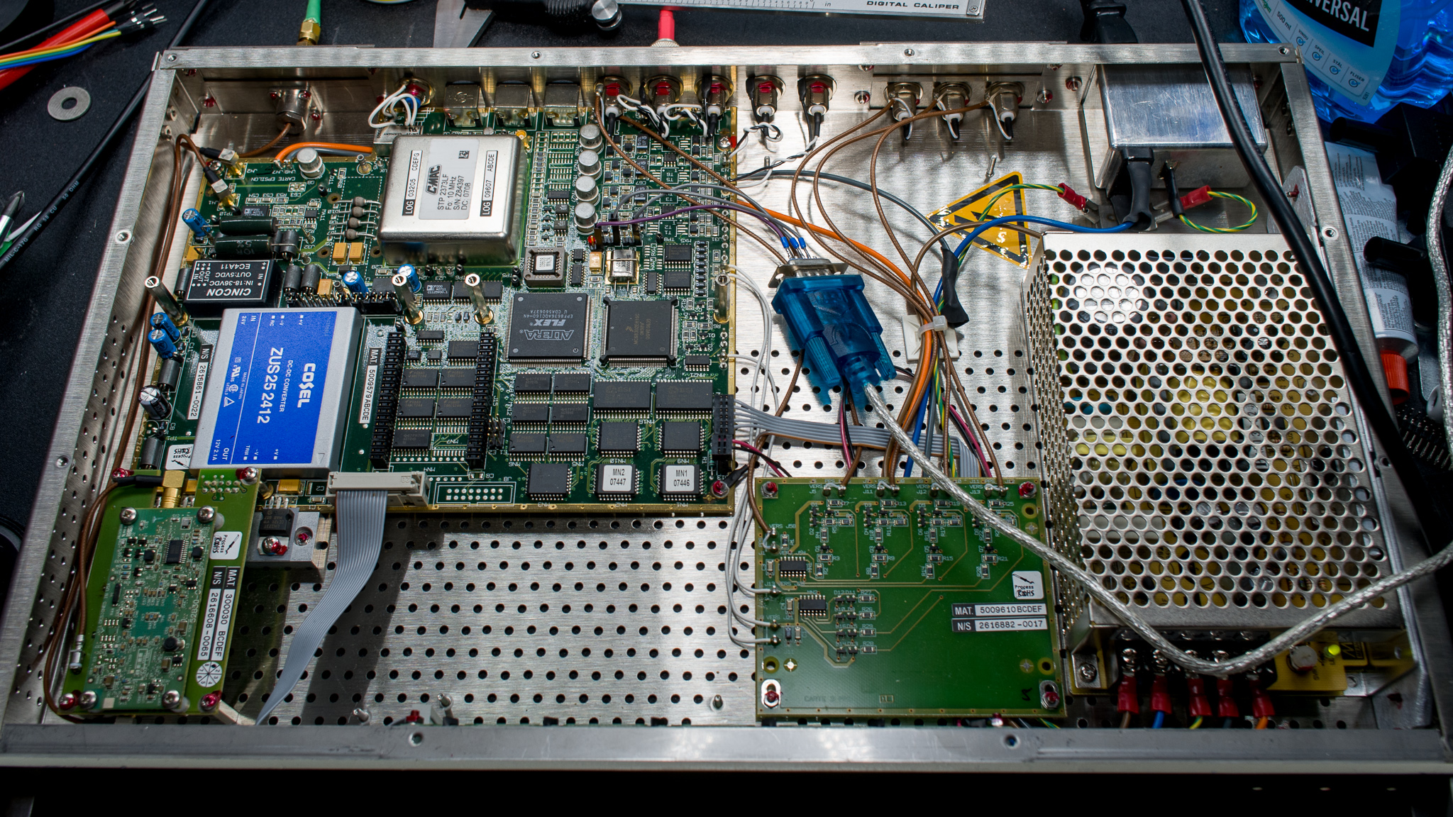
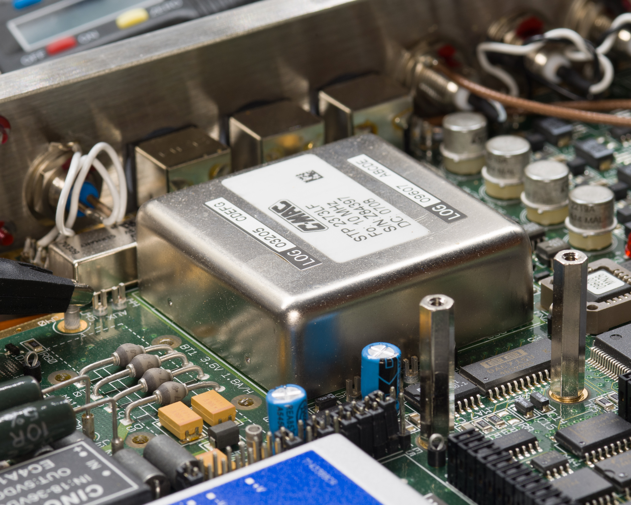
The OCXO is a C-MAC STP 2373F, no data was available on this module at the time of publication. C-Mac does not seem to be making OCXOs at this time.
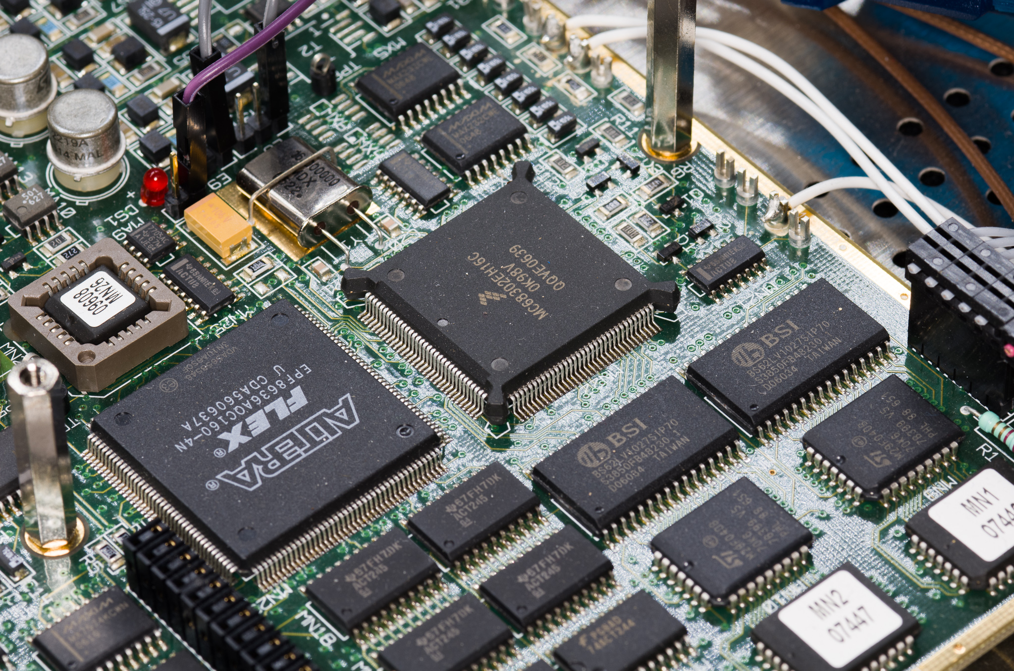
A Motorola 68k processor and an Altera Flex FPGA make up the bulk of the processing capacity.
The OCXO DAC is a Burr Brown (TI) DAC715U 16 bit voltage output DAC.
There's also some OP200 opamps, and an LT1054 (an improved ICL7660) switched capacitor voltage regulator made by TI next to it (possibly to generate a negative supply for the OCXO?).
The GPS module is mounted on a separate riser with a power regulator and a dedicated clock for some reason (looks like a standard XO).
The GPS module is a bare PCB version of a Trimble Resolution-T board, this might have been an upgrade considering the Trimble unit is a fairly new device but the clock has been in production since 1996. My unit was made ca. 2006. Other GPS receivers include the Motorola OnCore M12+.
The 2004 firmware also refers to VP and UT receivers, which are older Motorola OnCore models, but does not refer to the Trimble receiver, suggesting this may have been added after 2004.
It's not possible to talk directly to the Trimble module, but it's on a separate module with 0.1" headers so it's fairly simple to rig up wiring if that should be necessary.

The GPS biasing is (as is fairly common) biased separately on the main board instead of using the modules biasing circuitry.
This bias-tee is pretty terrible, it looks like an attempt was made at a half-wave stub matching but it wasn't very successful, I measured 6-7 dB insertion loss with a lot of ripple indicating poor impedance matching.
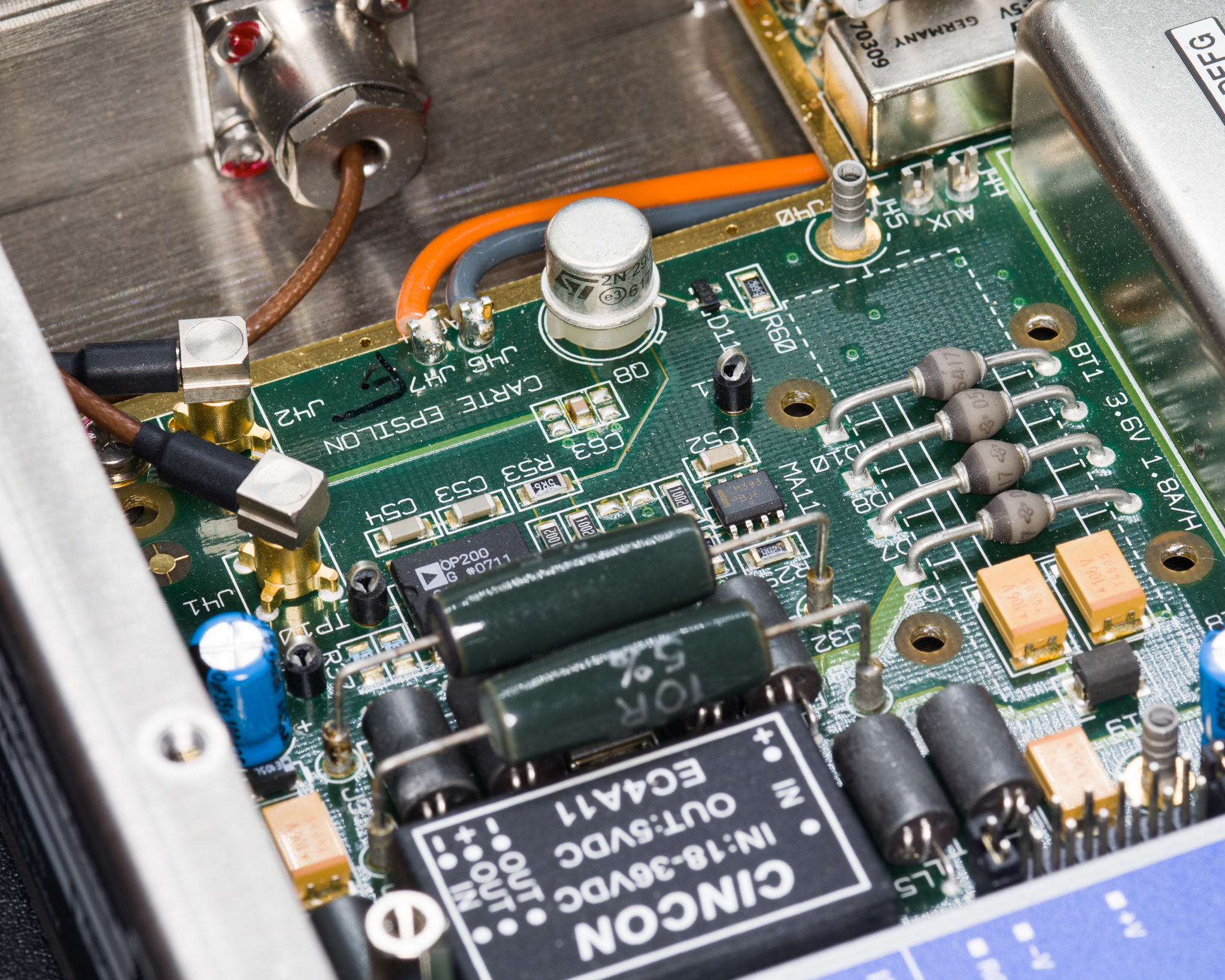
Also shown above is a location for a battery listed as 3.6 V/1.8 Ah; this battery seems to be ORed with an internal supply, it does not seem to attempt to charge the cell.
I attempted to power cycle the unit with the listed 3.6 V applied but it didn't seem to accomplish anything, the unit still restarted a full survey. Since a battery isn't listed as an option it's possible this feature isn't used at all.
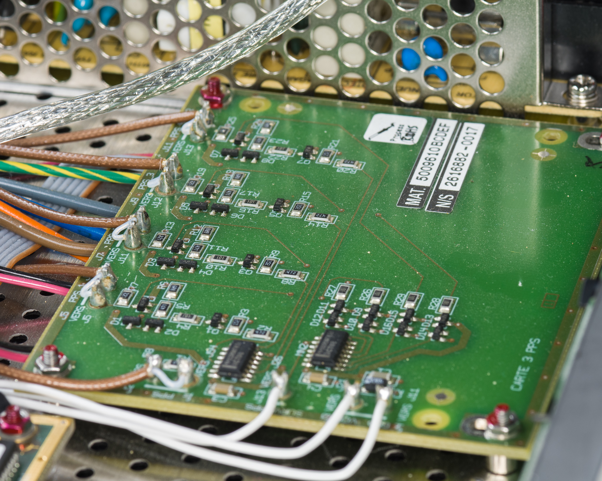
Various option boards can be installed using nice PCB solder turrets (the kind you mostly find in soldering training classes these days).
My unit came with a 1PPS option board providing three additional outputs, this board also includes a check that all outputs are active by ANDing all the outputs and routing this back to the main board.
It's possible that various option formats like IRIG can be found on some of these terminals.
It's also worth noting that the power supply is a Mean Well of some sort, the voltage is approx 32 V, suggesting that there's a diode OR bridge that selects the 24 V input or the internal power supply. The unit does not seem to know or care about the type of power supply in use, suggesting the input stage is fairly passive.
Talking to it
The RS-232 port is two way, and a software utility called EpsilWin32 is available from Spectracom to program it.
This software was not available for a long time, so I wrote my own tool (see bottom of this article).
Updated 2022: A kind reader found a copy of the original software and sent it to me, it can be downloaded here: EpsilWin32.zip. This software appears to support firmware upgrades and comes with a single firmware file from 2004, this might be relevant if you're e.g. kitbashing a few units together and e.g. want to stick in one of the newer GPS receivers in an old chassis.
Looking at the string table in the firmware it does seem that there exists either a separate serial port, or a debug mode which can print failure info. The firmware version appears to be version 9.00, while one of my receivers reported model 9.81 suggesting this is a newer revision. Unfortunately no dump is available, I believe one feature added in the newer revisions is support for Trimble Resolution-T receivers.
To get a serial connection, you need the Mini-DIN plug listed above, the pinout is:
- 3 - Serial Out from Clock
- 4 - Ground
- 5 - Serial In to Clock
- Pin 1 seems to have a 1PPS output (listed as reserved)
- Pin 2 and 8 are also reserved and may have other interesting signals
As noted above the levels are RS-232.
If you don't have a Mini-DIN plug, you can connect to some pin headers inside the device:
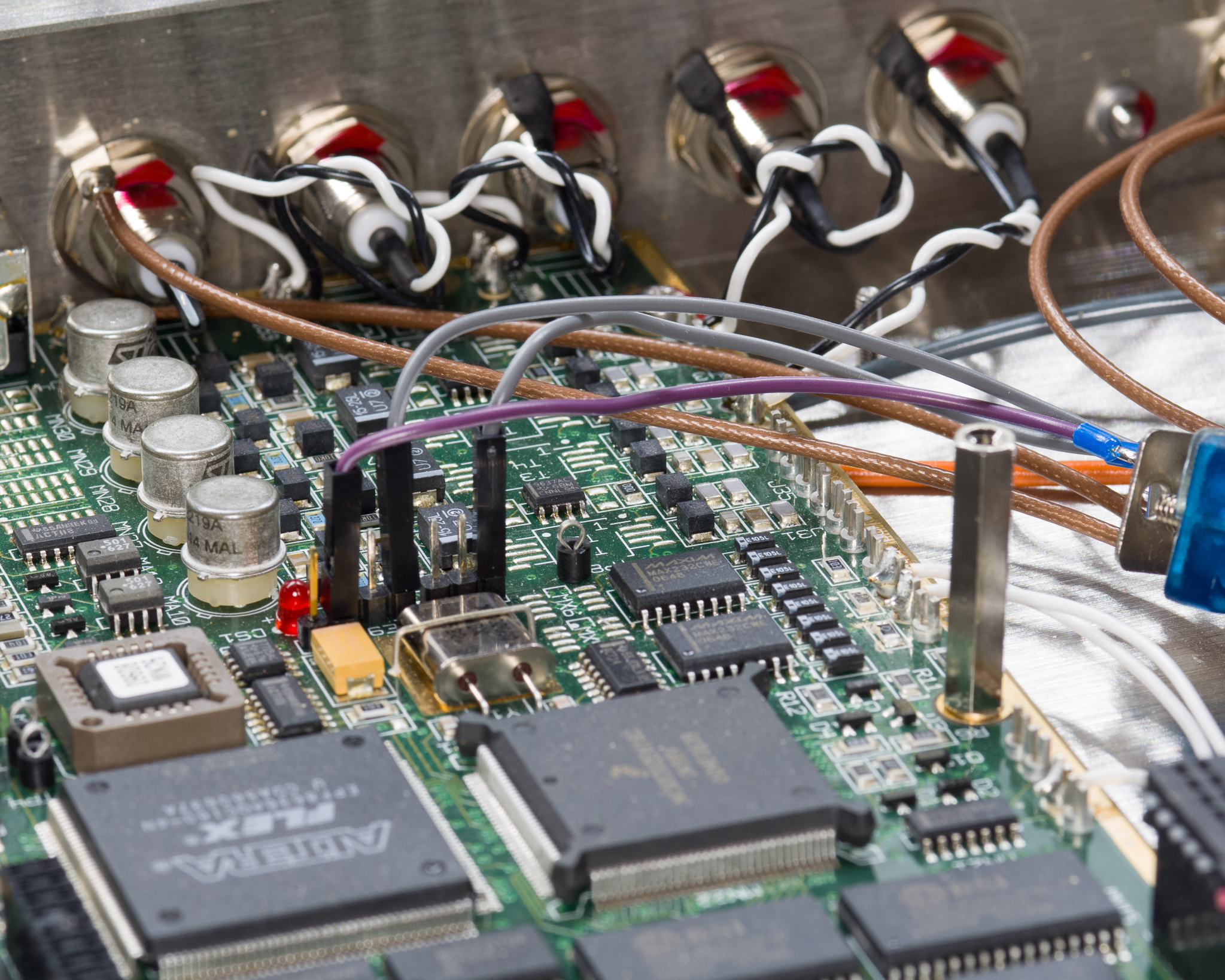
Note that in the picture above the ground is connected to a 2-pin header next to the RS-232 header.
There are jumpers installed by default that connect the MAX232 devices to the RS232 plug.
In Use
These devices run ridiculously hot, the stainless steel chassis doesn't help.
I've found several of these devices have issues with overheating and random resets, making them fairly unreliable. They are probably more reliable when installed with forced air cooling.
I'd suggest buying something new instead.
2021 update: I have been informed that the units that run very hot are faulty, and properly functioning units run both cooler and far more reliably. I have yet to see this happen though.
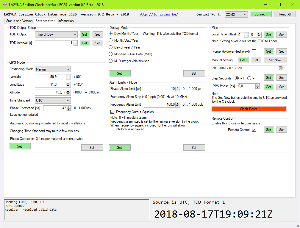
EpsilWin_LA2YUA
I wrote a utility to talk to the software based on a single EC2S unit and the data sheet information, it is available as open source on GitHub and a compiled version is available for download here.
This version is feature complete with the exception of some oddball commands that are largely irrelevant for most users.
Version 0.3 is written in Visual C#, targetting .NET 4.0, this is available by default in Windows 8 and newer.
Future versions will however be targeting .NET 4.5, which is default in Windows 8 and newer. It is supported as a separate install on Windows Vista SP2 and newer.

To download version 0.4 (compiled Exe), click here: EpsilWin_LA2YUA_V0_4.exe
Starting with version 0.4, source releases are tagged in the GitHub repo and not distributed with the compiled Exe.
To download old version 0.3 (Application + Source) click here: EpsilWin_LA2YUA_V0_3.zip
The source code is hosted here: https://github.com/longview/EpsilWin_LA2YUA
An information tab is included that explains certain functionality and limits are largely set to prevent bricking units, but reading the data sheet is recommended.