The 3021N Demodulator Card (Part 5)
This is part of a series covering the 3021N communications receiver. This part covers the Demodulator, and was the third part of the receiver that I replaced with a modern expansion. The demodulator card was finished in the middle of 2020 (I wasn't too busy).
Table of Contents
Original Hardware
The original card simply performs either envelope or synchronous demodulation based on some control switches. The synchronous LO is either a fixed or variable 8 MHz.
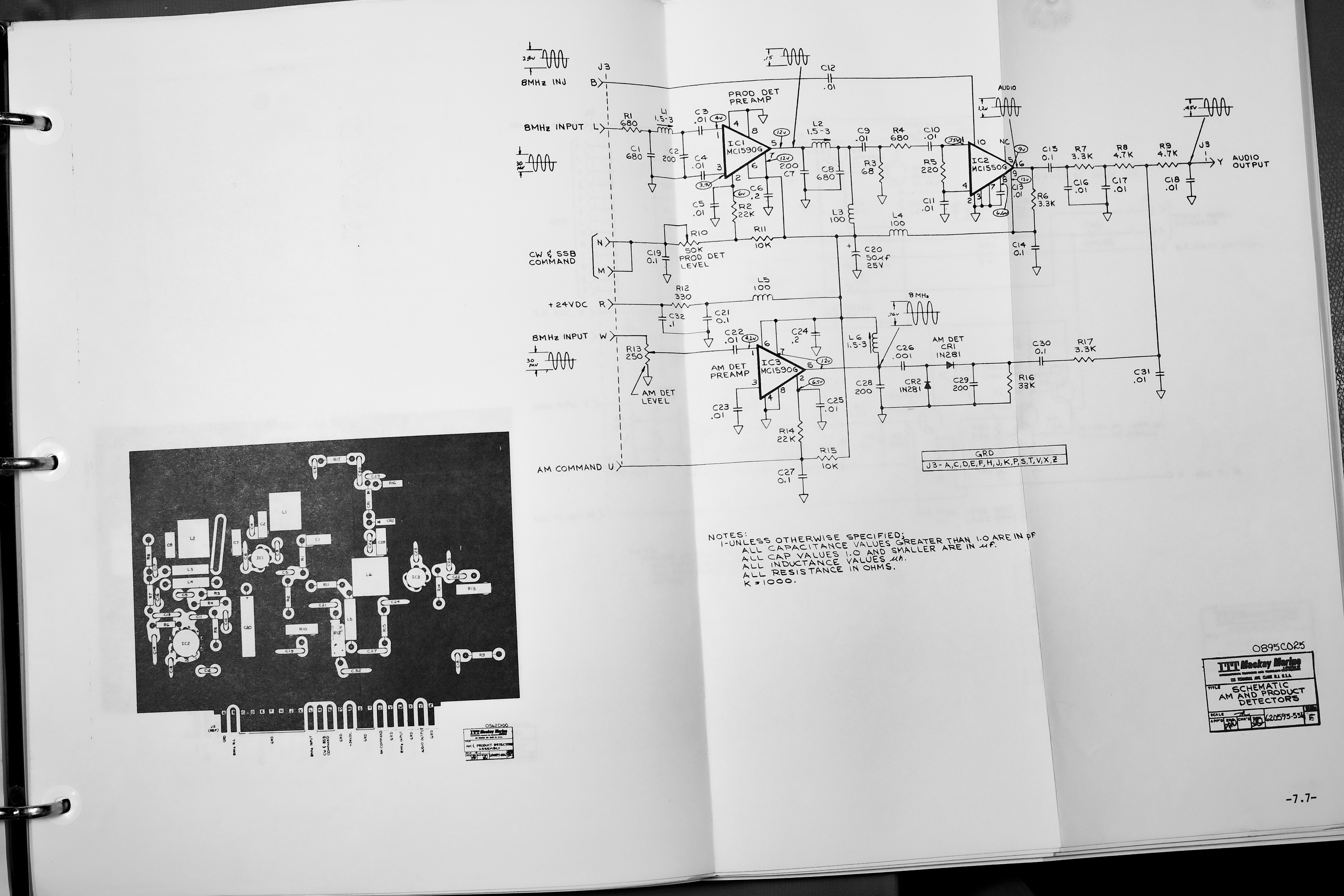
The main issue I sought to eliminate here was the poor performance when DXing AM broadcast, since the receiver had no synchronous AM mode (not surprising).
Basics of Synchronous AM Reception
The key feature of this new demodulator is the synchronous AM reception. This is a more complex receiver type than the conventional AM receiver, which is then called an envelope detector to avoid confusion.
A standard AM receiver uses rectification and filtering to detect a change in signal amplitude. The output then follows the envelope of the signal, hence the name.
By convention, AM transmitters are double-sideband with carrier as shown below:

The upper and lower sidebands are spectrally mirrored, and contain the audio spectrum that is transmitted. If a 1 kHz tone is transmitted as AM, the spectrum will contain a carrier and two tones at ±1 kHz relative to the carrier.
An AM envelope detector can detect these signals, though they also work if only one sideband is present – this is rarely done for broadcast signals, but was used for normally SSB 2182 kHz emergency transmitters to ensure compatibility with legacy AM receivers.
The big deal with synchronous AM is that when multi-path interference notches out parts of the received RF spectrum, the carrier may be notched out but the sidebands are mostly left intact. An envelope receiver will produce significant distortion in this case, since the modulation index of the AM signal is the amplitude of modulation over the carrier level → with no carrier (notched out) the modulation index is infinite.
The principle of a synchronous detector is to regenerate or recover the AM carrier signal, and multiply the AM signal with this carrier – effectively removing the original carrier and putting our own. The idea then is that only the side-bands are demodulated – this would form a DSB or Double SideBand receiver, which is basically an extension of SSB or Single SideBand reception.

To receive an SSB signal, no coherent carrier is required, but the (implicit, suppressed) carrier frequency of the SSB signal must be known reasonably well.
With a DSB receiver, both carrier frequency and phase must be known, since incorrect frequency tuning will lead to funny aliasing effects, and incorrect phase leads to fading as the signal crosses between in-phase and quadrature-phase.
At 90 and 270° offset between the local oscillator and received signal oscillator the output of the mixer will drop to zero (or rather, it will detect the quadrature-portion of the AM signal, but this will just be noise).

Above a conceptual drawing of what occurs in a DSB receiver with frequency error is shown, the frequency error results in spectral doubling, which is fun!
Not shown but explained, when a DSB receiver has a very minor frequency error or simply phase drift, the audio will fade in and out as the relative phase of the incoming carrier drifts through nulls every 180°.
A modification is to use SSB filters, in this case the receiver operates as an SSB receiver with automatic frequency control, the quality of the recovered carrier is less important since the phasing issues are not a problem in this case. Since only one sideband is used, spectral doubling doesn't occur due to incorrect frequency recovery. The penalty is that the increase to SNR yielded by coherently summing the two sidebands no longer applies, but if one sideband contains interference then suppressing it can still improve reception.
Note that a synchronous receiver does not require a particular signal level for the carrier, unlike an envelope detector, the level must be sufficient to allow detection of the carrier but any additional carrier power is not required. Note also that a Costas loop can in theory be used to recover a double-sideband signal without a carrier, since the two sidebands should contain the same information and align perfectly when the (implicit) carrier frequency and phase are aligned.
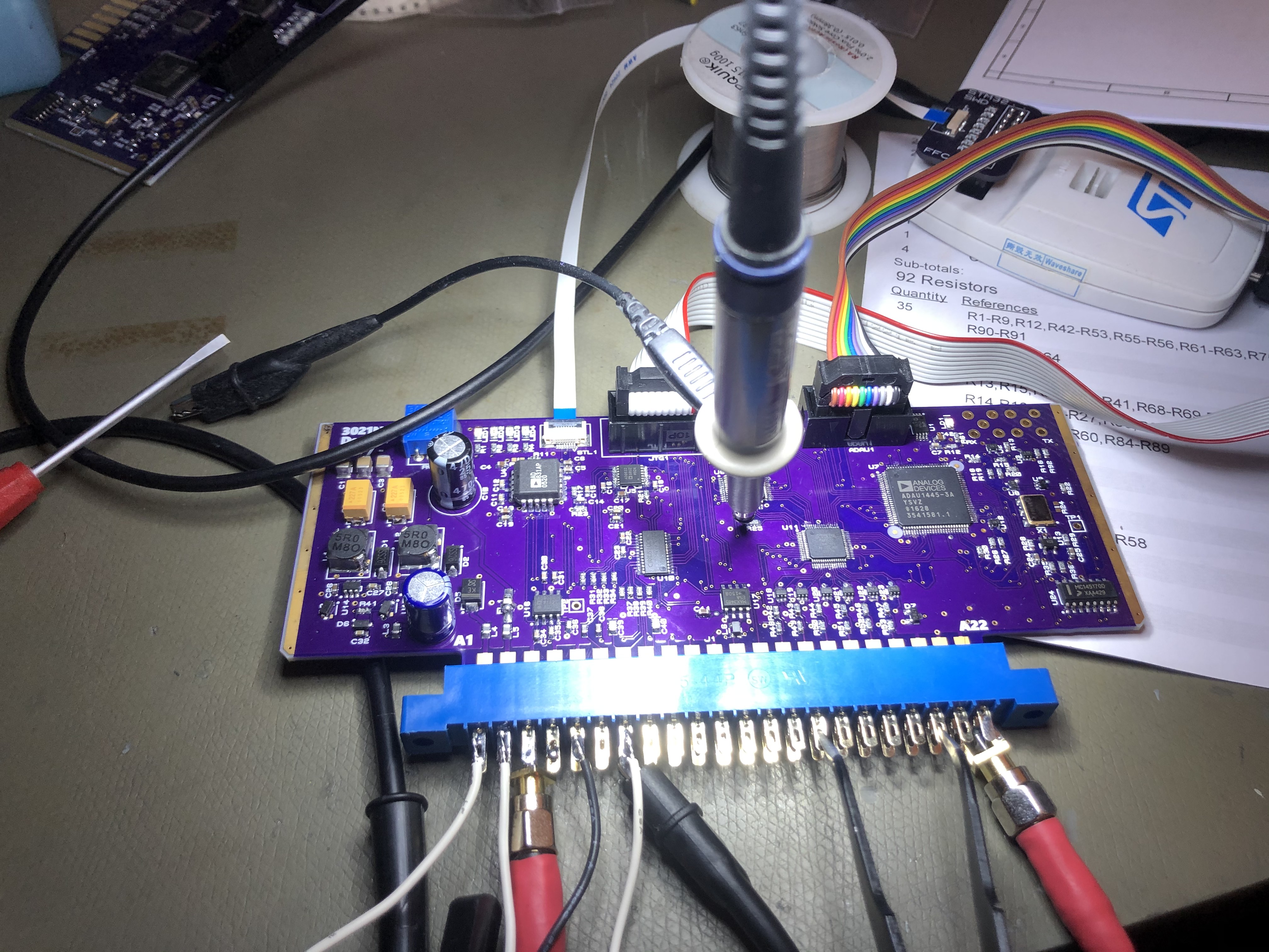
Hardware
The new card fits in the card cages like most of the other cards. It takes +5 and +15 V supplies, and its primary function is to accept an 8 MHz IF and generate audio from this.

To support this, the IF is amplified using an AD603 IF VGA, and mixed down to a 12 kHz IF using an AD831 double balanced mixer. The IF is then digitised in a CS4272 audio codec running at 48 kHz.
The mixer local oscillator is generated using an AD9832 32-bit DDS generator, which has extremely high frequency resolution.
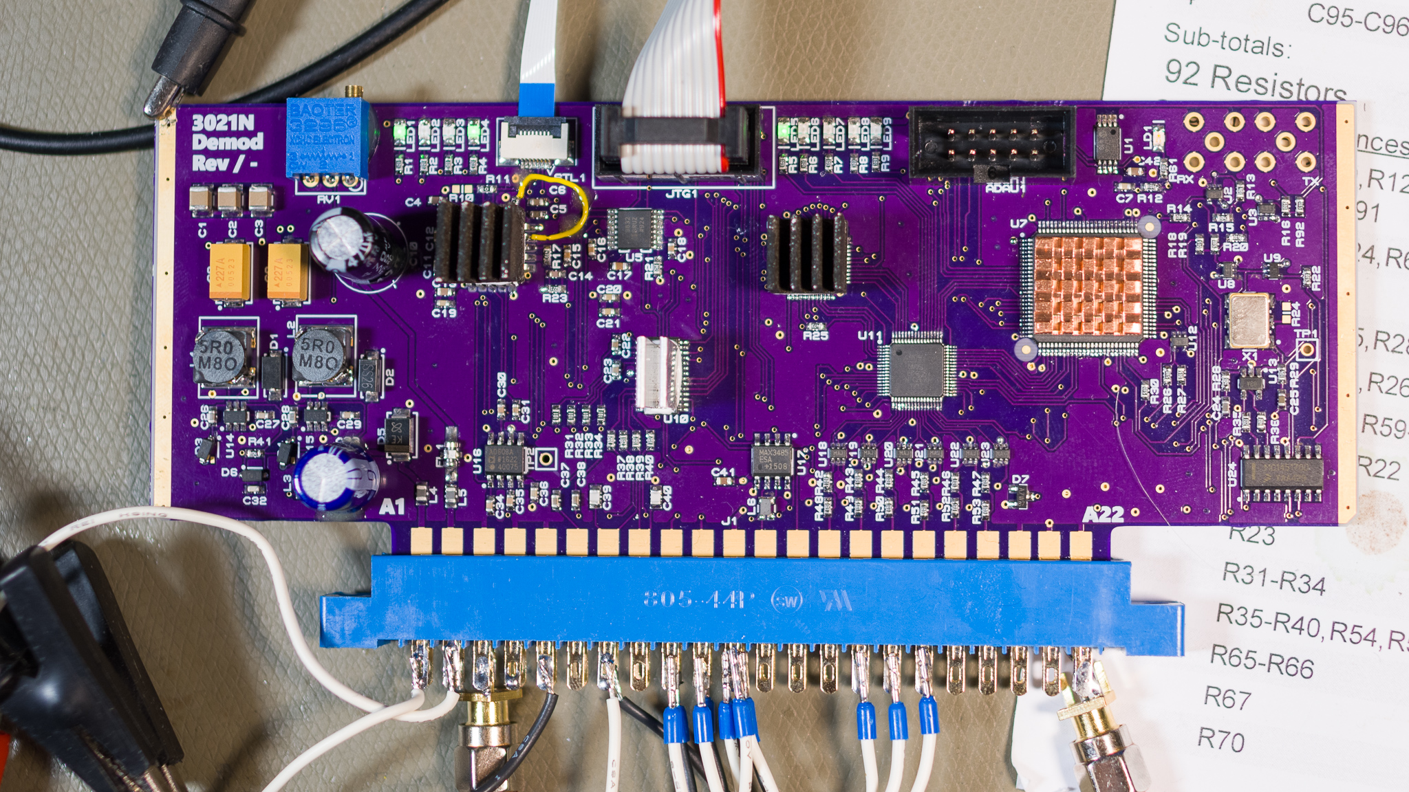
The system also takes the "LO3" input, which was originally 8 MHz but was later changed to 20 MHz. This disciplines a 24.576 MHz VCXO through a PLL, and this clock is used to clock all circuitry on the board.
The main processing unit is the ADAU1445 SigmaDSP, and this is paired with a MAX V CPLD from Intel/Altera – my first design using one of these. A STM32F303 mixed signal MCU performs the system control.
A set of high voltage digital inputs are designed to piggyback off the IF filter control lines, which were switched 24 V DC. These are available to the MCU through a CPLD SPI interface.
A F-RAM IC is also present but currently unused since all state is derived from button states.
The S/PDIF interface can be routed to unpopulated coax connectors or through a flat flex cable.
The original 3021N front panel includes a fine tuning potentiometer with pull-switch to enable this function. Originally this was wired into the synthesiser where is controlled a VCXO directly, for convenience I chose to re-route this into the demodulator, where the potentiometer is mapped to a DDS LO frequency offset of ±100 Hz. This corresponds to ±1 LSB on the tuning display, meaning any minor frequency offset can be corrected.
Performing this fine tuning after filtering means that the frequency offset no longer effects pass-band filtering in the IF filtering stage, but since the smallest crystal filter was 400 Hz this makes very little difference in practice.
Demodulation
The new demodulator card implements software defined filtering and demodulation, and supports:
- AM Envelope
- AM Synchronous
- DSB and SSB AM demodulation
- CW
- SSB
It also implements controllable 2nd order low pass filters, and AM noise reduction/squelching.
The DSP uses slightly less than 50% of the available resources, leaving plenty of room for expansion.
Frequency fine tuning from the front panel is implemented on this board as well, this is simply done by offsetting the DDS generator frequency.
Basic Demodulator Blocks
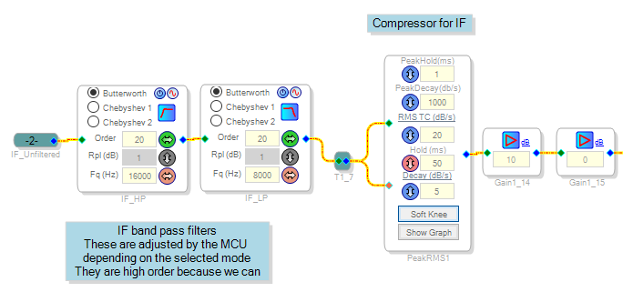
The digitised IF is sampled at 48 kHz, and is centered at 12 kHz. The signal is routed through a 20th order IF band-pass filter and AGCed to prevent saturation and compensate for level mismatches. These sharp filters may be removed or slackened later since the new 2nd IF Processor already does this job.
A TODO is to both adjust these filters, but also work out a filter-coefficient calculator; at present these filters are adjusted to match the selected IF filter and mode, but this is done using lookup-tables. At the time of writing, ADI has not published calculator code for the high order filter blocks, but they appear to be a chain of 2nd order filters based on the memory layout.
Another TODO is to increase the maximum AF bandwidth to e.g. 4 or 5 kHz, since many signal chain elements here and in the DSP board are capped at 3 kHz (sensible when built, but no longer applicable).
The filters and modes are adjusted based on the combination of demodulator modes and filter selections made on the front panel.
The signal is then detected in either a synchronous detector for SSB or CW, or a quadrature PLL detector for AM.
The synchronous detector is just multiplying the IF with a 12 kHz sine wave for SSB or e.g. a 12.5 kHz wave for CW to yield a side-tone.
The quadrature detector is detailed below.
The demodulated signal is routed through a filter selector, then to a DAC going to the DSP card. The filters consist of:
- Bypass
- Carrier Sensing AM Noise Reduction
- Adjustable 2nd Order Low Pass (controlled by the potentiometer knob in all modes except CW)
- Adjustable Q Band Pass (CW, ultra narrow)
Synchronous Detector
This is the SSB/CW detector, it is the most basic type.
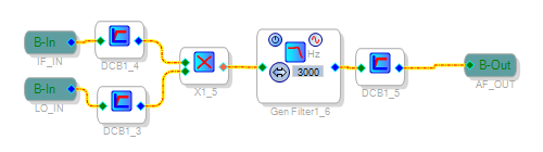
The input is multiplied with a tone, yielding a frequency translation. A low pass filter removes the sum output, and DC content is removed before outputting. The incoming LO is either 12 kHz for SSB, or 12.5 kHz nominal for CW.
Quadrature PLL Detector
The quadrature PLL detector is used for AM demodulation (both synchronous and envelope). This detector uses a dual loop carrier recovery system, one of which is shown here, the other is shown later since it extends beyond the DSP.
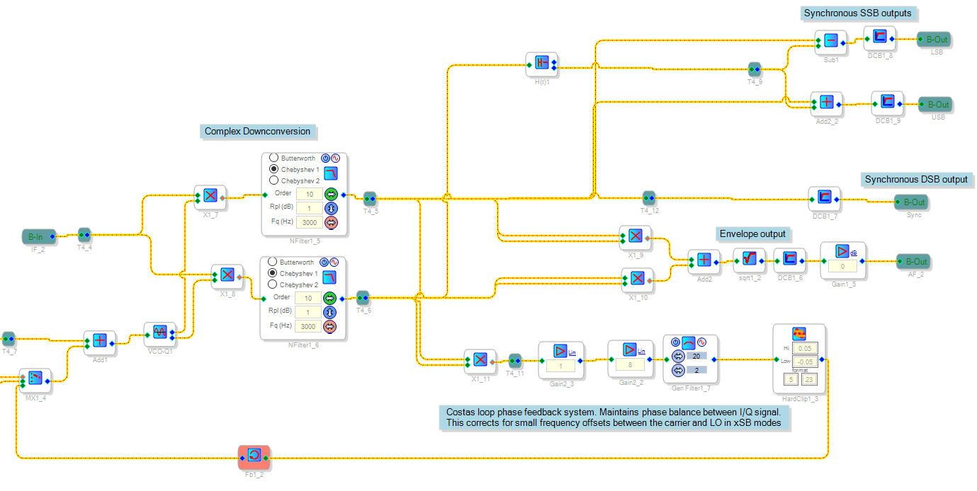
The principle is to down-convert the IF using a quadrature demodulator, which is two mixers supplied with in-phase and quadrature phase clocks. Each output is then filtered using identical low pass filters.
The I/Q signals can then be used in a various ways to achieve either DSB, envelope detection, or upper/lower sideband detection.
The DSB signal is simply the I branch (the Q branch should be mostly silent).
The envelope detector is the RMS sum of I and Q, this is identical to simply taking the RMS sum of the IF directly.
To detect one sideband and not the other, the SSB outputs are generated by phase shifting the Q branch by 90 ° using a Hilbert transform, then the I/Q' signal can be added or subtracted to yield a specific sideband. This allows implementation of the SSB/AM-Sync modes mentioned initially.
In order to correct for small phase errors between the external phase locking loop and the actual detector, a Costas loop is implemented in the DSP. This is implemented by multiplying the I and Q signals, low pass filtering the result, then applying this to the VCO clock generator. This is functionally equivalent to using an XOR phase detector in a PLL. Note for later that this demodulator uses an internal VCO, that is technically free running vs. the outer PLL reference clock. The outer loop ensures that the incoming IF is perfectly centered on 12 kHz, and the inner loop eliminates any residual error.
Note that both the Costas loop and outer DDS loops are active in the envelope detection mode as well, though they have no negative or positive effect in that mode.
It is worth stating that a more sophisticated DSP could certainly perform full PLL tracking in software, eliminating some external circuitry. This was attempted but it appears that the numeric resolution (28 bit) is not sufficient to smoothly control the frequency of the internal tone generators to track phase properly, so the external DDS based frequency tracking described below was used instead.
The SSB and DSB outputs work basically exactly like synchronous detectors; they only work well when tuned to exactly the right frequency and phase.
This makes tuning with a synchronous AM receiver exactly like tuning with a DSB receiver, and you can hear the AM carrier whine while tuning. It also means that e.g. CW or RTTY signals sound normal in this mode, except that the PLL system will try to lock to them.
I like to call this a "precision" receiver, given that it requires tuning to within ±50 Hz before the PLL will start tracking properly. In a normal envelope receiver it can be hard to tune exactly onto a station, while in this one it's impossible not to.
Synchronous AM PLL System
The synchronous AM PLL system is rather complex, the core is the quadrature demodulator mentioned above. This can autonomously recover the carrier within a narrow window, and will keep the final phase of the local oscillator in control.
The block diagram below shows the inner Costas loop (mentioned in the previous section), and the outer DDS based loop, which is implemented across four different domains (Hardware, DSP, CPLD, and MCU). Note that all elements are clocked from the same 24.576 MHz source in this system.

As established above, the incoming IF is down-converted to 12 kHz using a high precision DDS generator and mixer. The principle here is to allow the DSP to use a "free running" 12 kHz clock (which is clocked off the main radio timebase). The external control loop then compares the DSP's 12 kHz carrier with the recovered carrier from the incoming signal, and adjusts the DDS clock generator to close the phase locked loop.
The DSP does carrier detection, and generates a local 12 kHz square wave, these are sent to the CPLD over a standard I2S interface:
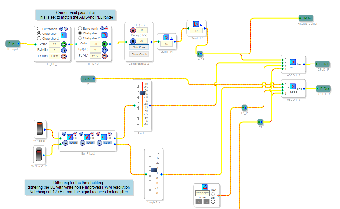
Above the DSP blocks to extract the incoming IF carrier is shown. This is simply a high order band pass filter centered at the IF ±50 Hz, and some AGC is applied to this signal as well.
The result is basically a sine wave, and this is thresholded and output to the CPLD as one channel of a stereo pair. A free running 12 kHz signal makes up the other pair. Since we are operating with square waves at 48 kHz, a dither is applied by generating band-shaped white noise which has no energy around 12 kHz. This added noise reduces the dead-band of the two signals, which is quantised to basically 5 different relative phases by the thresholding and sampling at 48 kHz.
The CPLD accepts this I2S pair and time-aligns the two channels as two square waves, which is applied to a basic PFD inside the CPLD. The output is a PWM that is low pass filtered and digitised by the STM32F3 ADC.
Above the analog PFD output is shown achieving lock, without noise shaping the signal would have even more significant phase dead band. This phase dead-band is not critical since as mentioned the demodulator circuit has a local Costas loop to correct fine phase errors.
The STM32F3 implements a PID controller that adjusts the DDS generator to maintain a stable phase lock. The controller has various features beyond a standard PID, such as time-variable gain, basically when it's unlocked it's fairly aggressive, but when achieving lock the gain of the regulator is reduced over time. This allows it to maintain a stable lock for very weak signals, without excessively long initial acquisition times.
As mentioned above, the current implementation has a ~±50 Hz tuning/capture range, but this is purely a software limitation. Extending the PID regulators output range and adjusting the band-pass filtering in the DSP would trivially allow for larger capture range. The receiver system has a tuning step of 100 Hz and an optional variable tuning offset potentiometer, so this range is sufficient to always allow correct tuning while keeping the bandwidth as low as possible to maximise performance.
In practice the synthesiser has an external 10 MHz input, so the receiver frequency tends to be extremely close to exactly right (limited by the DDS resolution of <~50 mHz), and most AM stations on air are also quite accurate. This means that the phase locking occurs almost instantly, but a side effect is that AM broadcasts with minor frequency errors are noticeably slower to lock in.
Carrier Sensing AM Noise Reduction
The principle of the AM noise reduction is to detect the ratio of carrier to side-band energy, and use this ratio to control a low pass filter and amplitude reduction. This feature requires relatively high precision tuning (within ±100 Hz) to achieve good performance, though it can be used with both the Sync and Envelope detectors.

It was originally intended to reduce noise pumping when listening to AM broadcast with significant flutter. The problem here is that the level of the AM signal is highly variable, and multi-path interference causes various frequency response notches, which is typically audible and sounds like a "phasor" effect.
A bigger issue is that when this notch hits the carrier, the effective modulation index increases and causes significant distortion in the receiver. The modulation index is the side-band power relative to the carrier power, and with no carrier the modulation index becomes infinite, yielding distortion in an AM envelope receiver.
This is one of the main reasons to use synchronous AM receivers, which generate their own carrier to use instead of relying on the signal to bring one. However, the radios AGC system will still increase gain when this happens, and this tended to cause increased noise levels when this fading occurred.
So the idea was to attenuate the high frequency noise, and drop the audio level when the carrier disappears. This worked quite well, but it turned out that with some tuning this system also basically cut out the audio entirely when not tuned to an AM signal.
This feature worked so well that it is basically considered the default for this receiver in AM mode, though the standard sync and envelope detectors have non-noise reducing modes for use with the DSP noise reduction modes, in particular the RNNoise network works better when fed the full audio bandwidth.
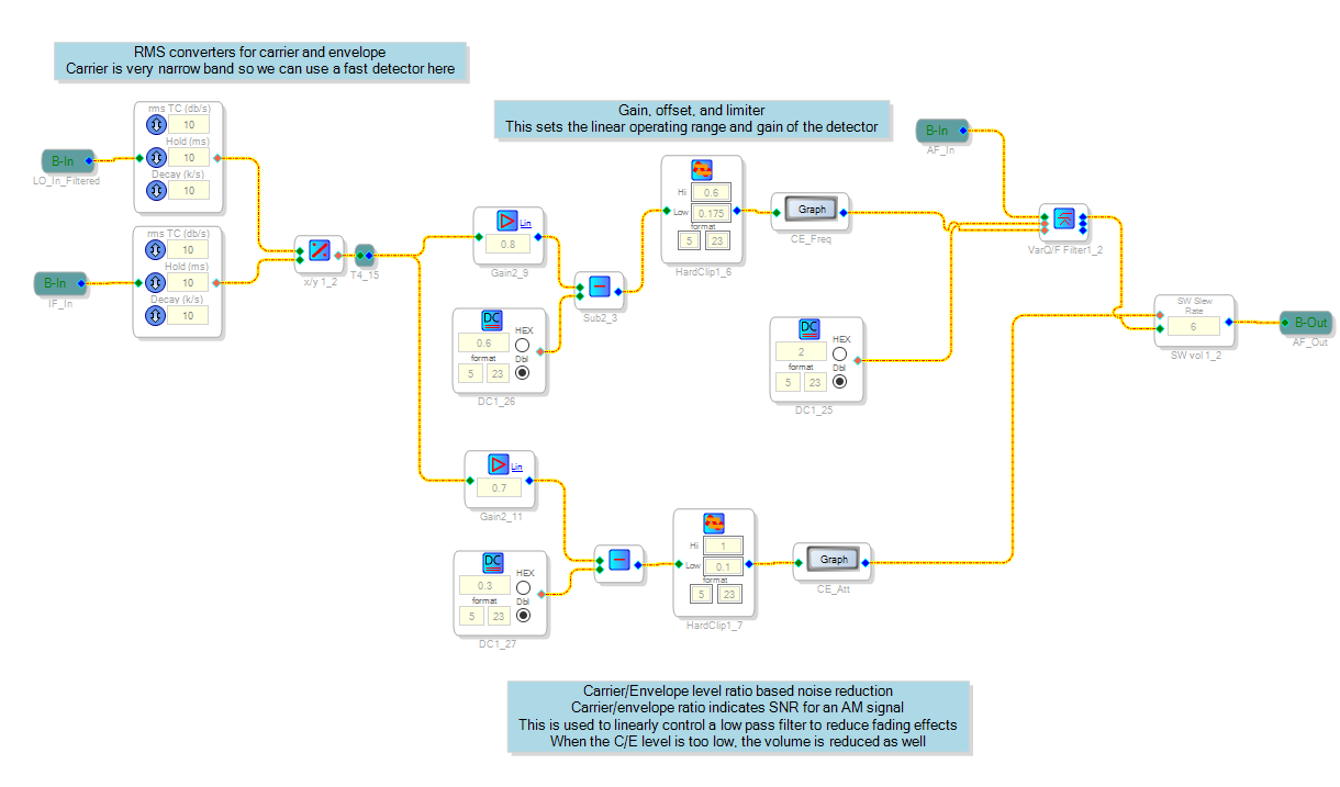
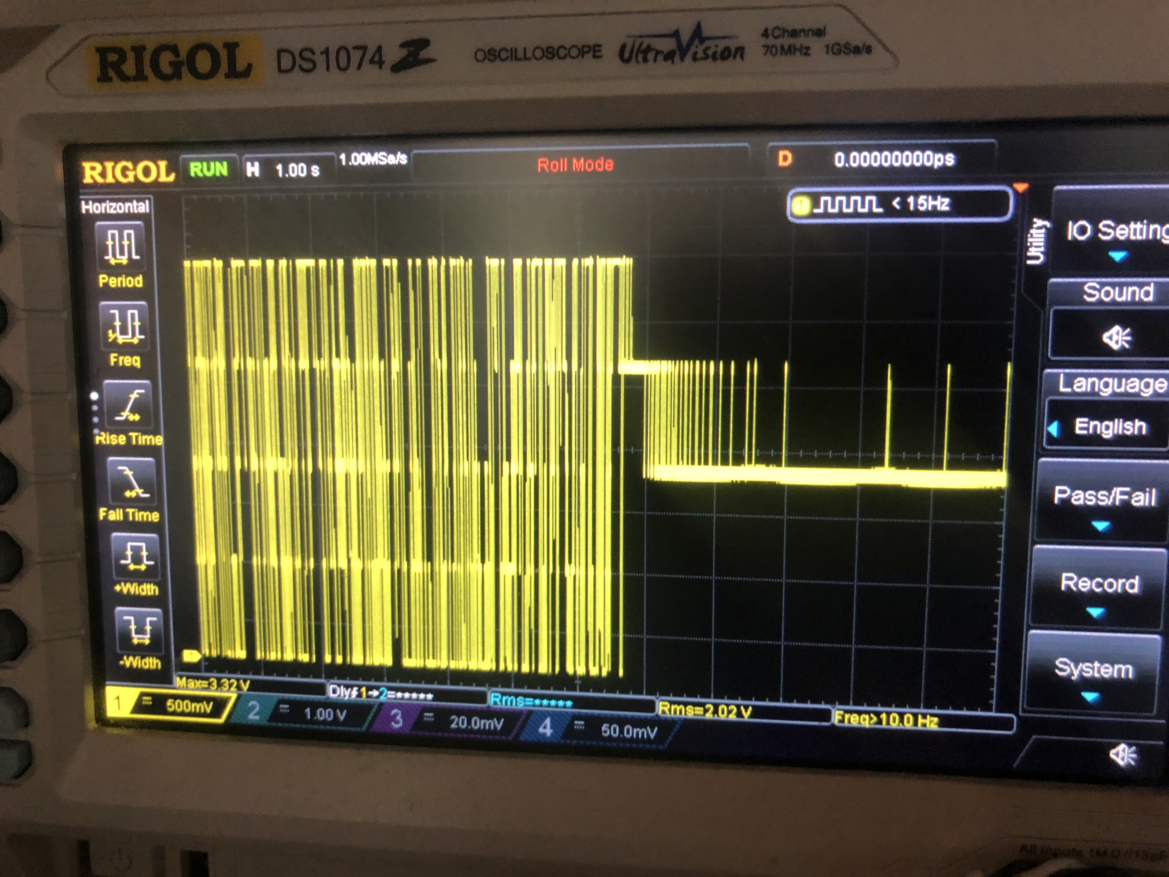
Above the DSP schematic for this functionality is shown. The IF and LO (from the CPLD PD block above) signals are RMS rectified and filtered. The corner frequency and amplitude of the output signal both follow the form of x=(carrier power)÷(full band power) where x is either the corner frequency or a scaling factor.
The low pass filter is always active but for a standard AM signal will have a cutoff higher than the audio bandwidth.
The gain level is only affected when the ratio is below a threshold; this functions as a fairly effective squelch, and as tuned here it strongly attenuates but does not entirely disable audio when flat noise is input. This was done since the synchronous AM receiver mode is easier to tune when the carrier-whine can be heard, and the operation of this noise reduction system requires fairly exact tuning of the receiver (extending the synchronous AM capture range would fix this issue though).
I am not aware of any other radio implementing this type of noise reduction, feel free to clone it for your own project.
An enhancement could be to also use a notch filter to split the detection into carrier & sideband power (perhaps even upper/lower filtering as well). This would likely improve the quality of the measurement somewhat, though as implemented it works fairly well.
Associated Hardware
At the same time as integrating this system, the front panel knob changes previously discussed were implemented.
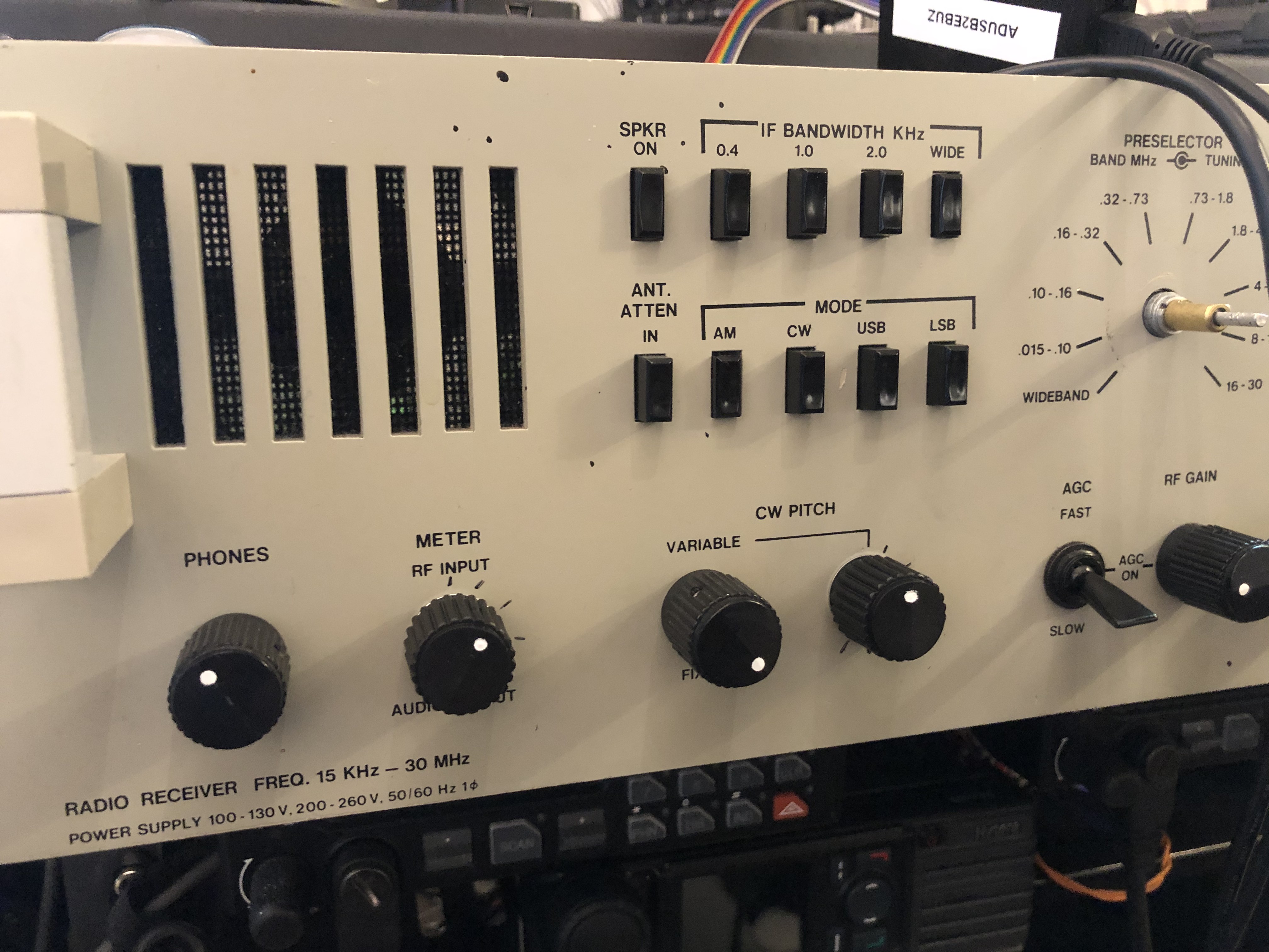
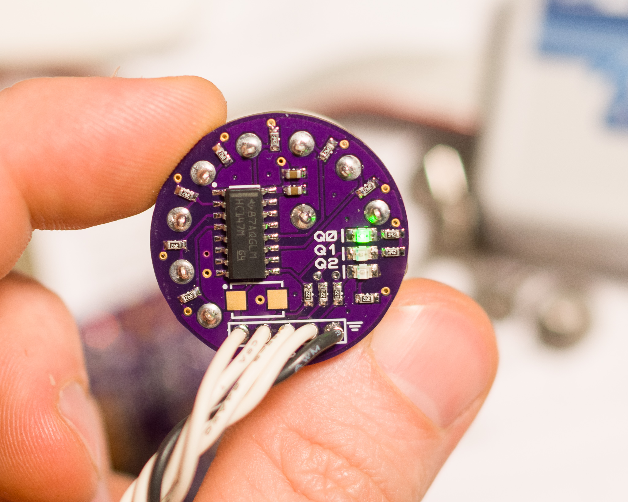
The 8 position rotary switch PCBs were also implemented for the demod and DSP card at this time, replacing whatever was there previously for the DSP (until then it just used a normal switch).