The 3021N DSP/Noise Reduction Card (Part 4)
This is part of a series covering the 3021N communications receiver. This part covers the DSP, and was the second part of the receiver that I replaced with a modern expansion. It replaces the Audio Amplifier PCA. This card was designed in late 2018.
Table of Contents
Audio Amplifier
The Audio Amplifier is the final driver for the speaker, headphone, and line output from the radio. This is a very large card for such a simple function, and consists of a pre-amplifier and output amplifier, followed by an output auto-transformer that converts the high impedance output to a 3 Ω level for driving the speaker.
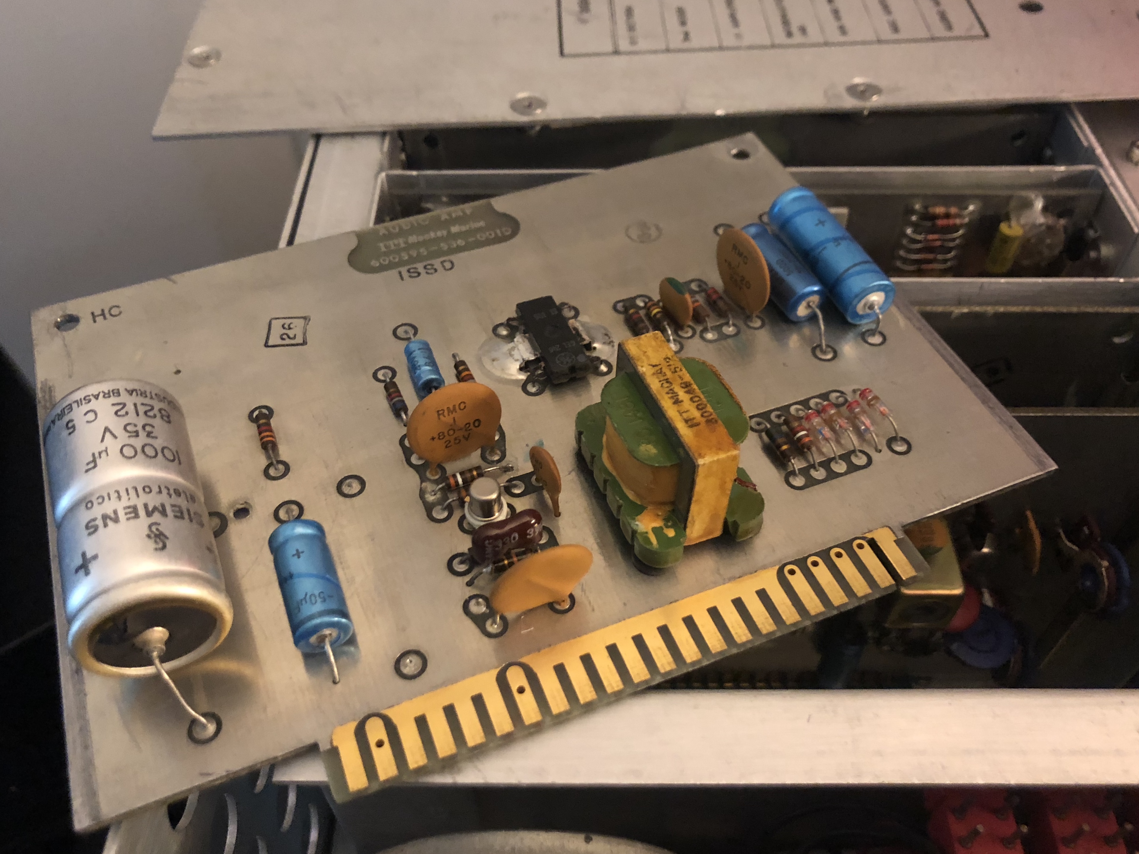
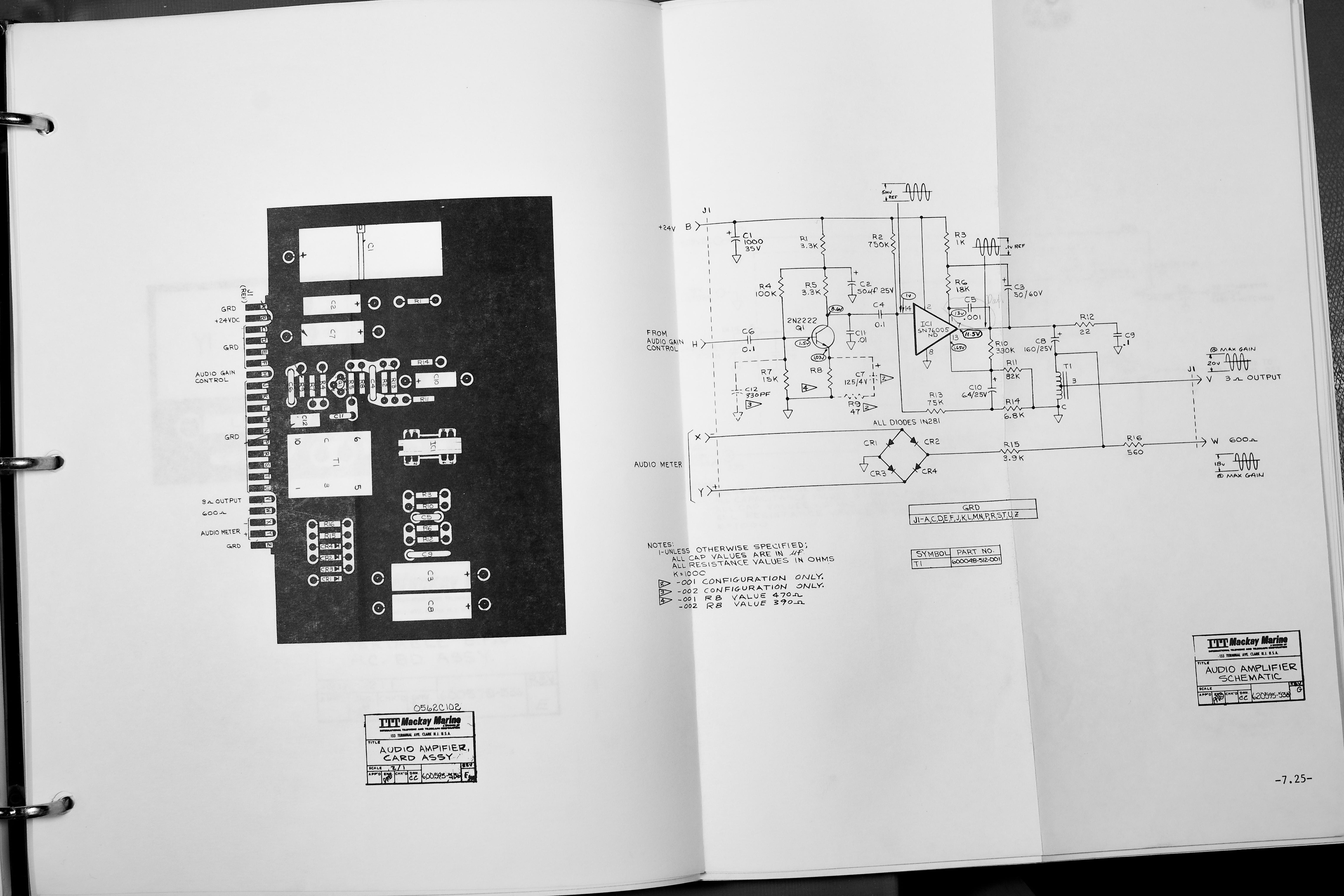
The card also generates the meter drive when the front panel switch is set to AUDIO, and this feature was unceremoniously dropped. As mentioned in a previous article, this was not well implemented to begin with.
The DSP Card
The DSP card was the first DSP card I designed, it implements the functions of the old card such as:
- Accept the AF from the demodulator
- Accept volume control input
- Drive the loudspeaker, line out, and headphone jack
And adds:
- Digital I/O via S/PDIF
- Speaker equalisation
- Independent drive for speaker, line, and headphone
- Noise reduction processing
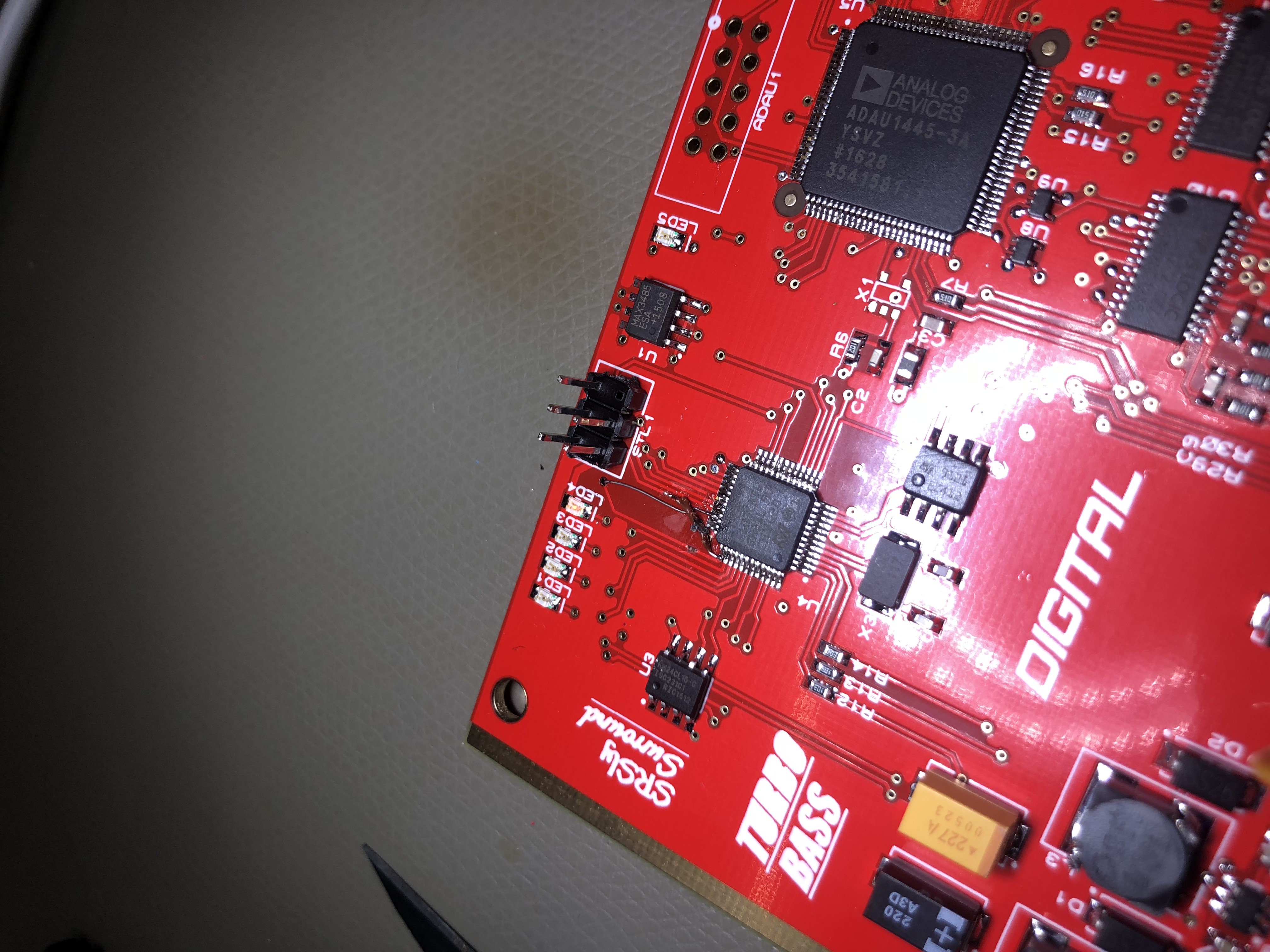
It has a relatively large DSP that can perform a variety of filtering functions including some basic noise reduction, and a STM32F407 MCU that implements a limited copy of the Xiph RNNoise neural network noise reduction.
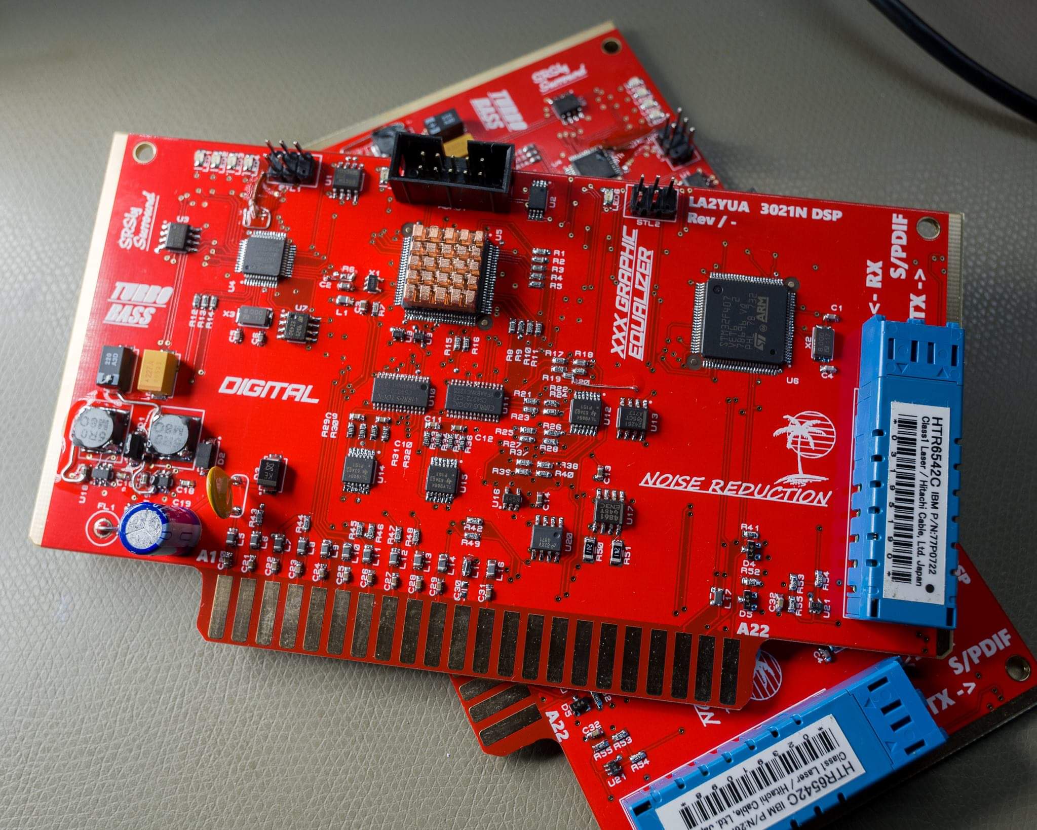
The main functionality is balanced audio I/O, and is controlled by a STM32F103 MCU. The audio core is a ADAU1445 "SigmaDSP" running at 48 kHz. The STM32F407 to the right is dedicated to the RNNoise functionality and is connected through the DSP.

The S/PDIF interface is connected to a SFF single mode optical transceiver, I already had a bag of these sitting around so the additional cost was very low. This interface has proven to be quite convenient for development, since it makes it very easy to hook up the fiber interface with clean audio to another copy of the DSP card.
I used CS4272 audio codecs for the interfacing, these are relatively cheap and quite high performance, even by modern standards.
For most of the analog processing the low cost TLV9064 CMOS opamp is used, and a LM4871 3 W linear bridged amplifier drives the 4 Ω speaker. This single IC more or less replaces the core functionality of the old PCB. The 3 W output power is more than adequate, especially since the new speaker has very high efficiency.
I also made a standalone adapter to break out all the I/O and power a second card, this was used as the initial development unit. It has proven to be extremely convenient when testing all kinds of new DSP functionality intended for implementation on different hardware.
SigmaDSP?
SigmaDSP is a family of application specific DSP's made by Analog Devices, these are highly customised for use in audio signal processing, and they target somewhat non-technical users. The target application is active speakers, basic mixers, sound bars, microphone array processing, etc.
Programming is done using a block diagram scheme in their (free) SigmaStudio software package – no instruction set or C compiler is even provided, though plugin developers can get access.
The DSP's have various feature levels, and appear to be based on modified/simplified SHARC DSP cores. The ADAU144x series is a mid range type, capable of around 4000 instructions per audio sample – roughly 180 MHz core clock – and supports around 20 inputs/outputs over various PCM interfaces similar to and including I2S and TDM.
These devices operate in 28 bit fixed-point, which can cause some issues when doing specialist operations but is basically sufficient for 24 bit audio processing with some internal headroom.
The processing features include a wide variety of standard audio functions such as all common filters, compressors/noise gates, parametric and graphic equalisers. A special equalisation feature is also present and can accept speaker-parameters and assists in designing correction filters. Some more advanced DSP features such as Hilbert transforms and feedback circuits are also possible, but e.g. computing FFTs is not possible on most models and all the standard filters are IIR types with very low latency. IIR filters are good for this use case, but some filters can have issues due to the limited numeric resolution, such as using 2nd Order low pass filter with very low cut-off frequencies (less than 2 Hz or so). This is only really done when processing non-audio signals.
Debugging is via SPI or I2C, and they support self-booting from an external I2C EEPROM. The USBi debugger/programmer can directly program the EEPROM for convenience.
If this sounds interesting, there are some ADAU1701 development boards that are relatively easily available from e.g. AliExpress. These appear to be a good place to start, though the ADAU17xx series is one of the more basic models it's still fairly capable and a good introduction to the series.
Some audio codecs made by Analog Devices include SigmaDSP cores, this is likely most common in laptops, where the internal speakers and microphones can be linearised in a dedicated DSP.
Signal Processing
The DSP in standard mode implements a high/low pass filter for the AF, a basic audio compressor to prevent overloading the outputs (normally not active), and a volume control.
The line output bypasses the volume control, as expected.
The RNNoise and "1894" noise reduction functions can be switched in, and the level of noise reduction can be set using a potentiometer and rotary switch on the front panel (this controls the DSP, no analog switching).
Additional features that could trivially be implemented would include low pass filters with e.g. adjustable Q, but these features are already implement on the Demodulator card so this functionality is not required here.
Resource-wise, the DSP can perform around 4000 instructions per sample, and currently uses around 1000 of these.
RNNoise
RNNoise is a neutral network noise reduction intended for real-time noise suppression, using FFT spectral subtraction controlled by a neutral network.
I built the basic RNNoise release from 2018, and modified it to run at 32 kHz instead of 48 kHz (the fastest it could run on the M4F core). The current implementation uses a custom trained network that is optimised for RF noise instead of the general purpose ambient noise reduction network.
It works very well for synthesised voices, and performs fairly well for AM broadcast, to the point it can be used as a sort of squelch function.
1894 Noise Reduction
The basic principle of this algorithm is to use a voice activity detector to control an audio low pass filter. This is based on the analog LM1894 tape noise reducer principle, which uses audio level detectors to control low pass filters to reduce tape hiss.
My implementation is built in the SigmaDSP block programming system, and uses a voice activity detector (VAD) block provided by the DSP to control a low pass filter with relatively high Q. When voices are detected, the low pass filter cutoff frequency increases proportionally.
The basic operation of the VAD is to compare the derivative of the energy in two frequency bands.
In this mode, the scaling factor between the (linear) VAD output and the low pass filter is controlled by the front panel potentiometer, allowing for control of how much attenuation of applied.
This type of detector has been found to work extremely well for narrow band FM reception, and it works reasonably well for AM broadcast. The reason it works really well for FM is that FM noise (hiss) basically starts at higher frequencies, so cutting in a low pass filter when no speech is sent can significantly increase the SNR. Unfortunately, this receiver doesn't include FM reception (but the new 2nd Converter card can do FM cross-demodulation).
Issues
Distorted Sound
The most unexpected issue I ran across was very high harmonic distortion in the speaker driver. This seemed to be largely independent of volume, and I spent a fair amount of time analysing the DSP and related software setup to find the source. The distortion was only present on the speaker output.
Eventually upon connecting an oscilloscope to the speaker output I noticed what appeared to be significant crossover distortion, and thought I had selected a terrible speaker driver IC.
Further measurement showed that the output from the IC pins were entirely clean. It turns out that the 120 Ω Vishay ferrites I had put in series with all analog and power I/O connections are actually quite hysteretic. Basically they would be a good choice for core memory. Every time the current through the ferrite changes direction the ferrites magnetic state will suddenly flip to a different polarity, and when this happens it generates a voltage across it.
The source was later verified by LTSpice simulation, using more complex hysteretic inductor models yielded identical waveforms. I fixed the issue by simply bypassing the ferrites for the speaker outputs.
RNNoise
On my TODO list is to investigate the more modern implementations of ideas similar to RNNoise, as some newer designs are more optimised for smaller processors. The conversion to operate at 32 kHz was not particularly thorough and e.g. the FFT bins are likely now sub-optimal.
STM32 I2S Interface
I also would like to get the digital audio interface on the F4 working, since right now the ADC/DAC on the F4 is connected to the DSP's audio codec which lowers the dynamic range.
The initial issues I had at the time was that the F4 was unable to operate as a slave device in any stable way, and I found that the left/right clock was not used properly. I may simply change the system to run off the F4 clock generator instead, this should be possible since the F4 and DSP share the audio clock anyway.