
The 3021N Scan Tune Logic (Part 3)
This is part of a series covering the 3021N communications receiver. This part covers the Scan Tune Logic PCA, and was the first part of the receiver that I replaced with a modern equivalent, in the middle of 2018.
Table of Contents
Overview
The Scan Tune Logic is the most major change between the earlier 3020A and this 3021N. The 3020A uses a set of BCD thumb-wheels to set the frequency, while the 3021N uses a much more convenient optical chopper, allowing for easier scanning.
The implementation is basically a retrofit onto the existing synth, so the Scan Tune Logic card emulates a set of BCD switches, keeping track of the tuned frequency in a set of 4000 series CMOS counters. The counters are battery backed to let them keep their state for some time after power is lost.
A key design issue with this circuit is that there is a switch on the front that select between fast, slow, and no (lock) tuning. It is obvious to anyone that you'd leave this in Lock when you're happy. Unfortunately the wiring is such that when in any state other than the "kHz" tuning state, the supply voltage is loaded with 11 kΩ to ground. This also includes the battery supply, and so it will drain rather more quickly than it would otherwise.
If the battery is dead, the circuitry will start up in weird illegal states, but cycling through and making all the digits wrap around tends to reset it.
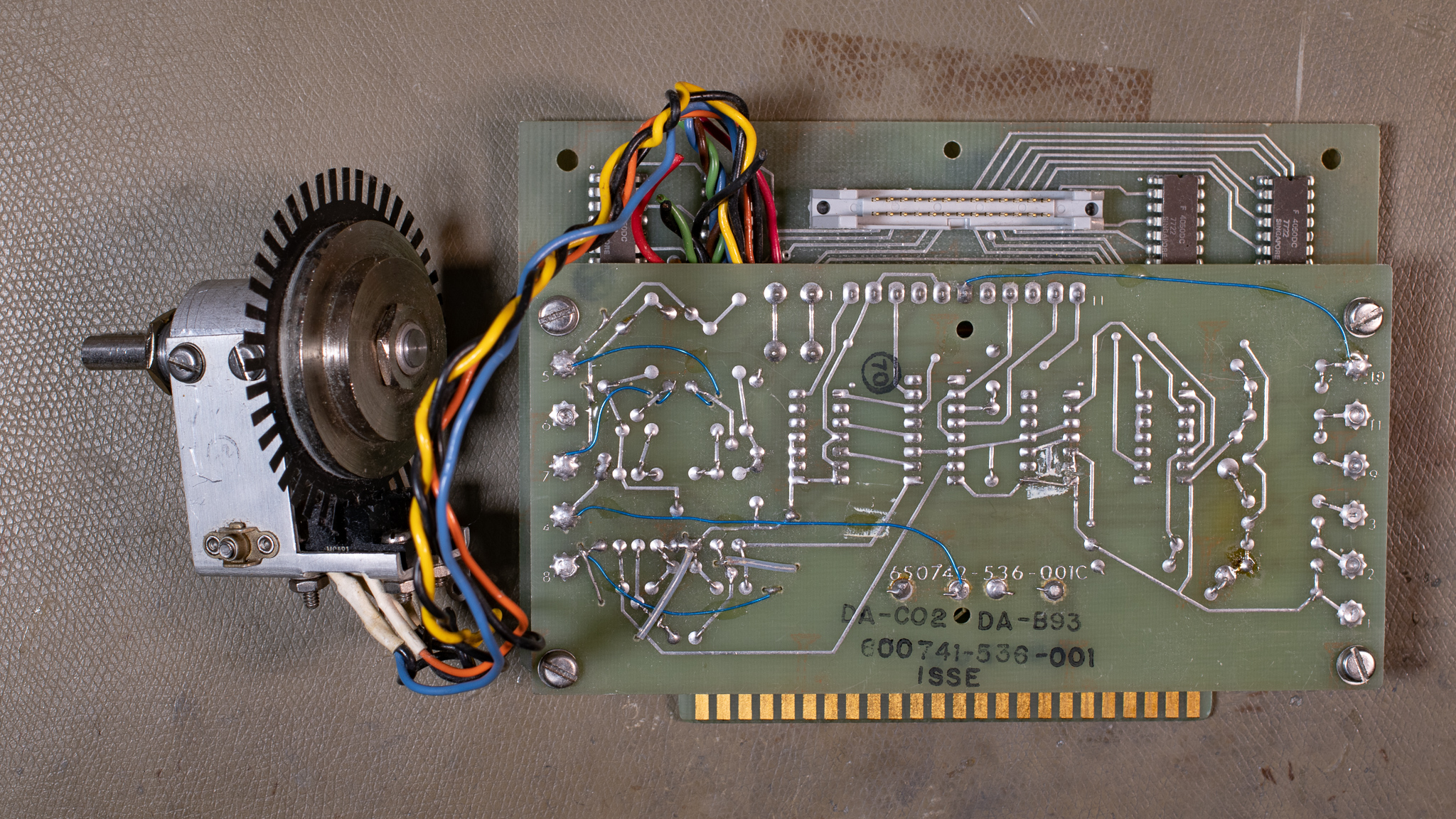
The optical chopper was built from a mylar sheet and two optical fork sensors, which are decoded using digital logic and generates count up/down clock pulses that are counted. The mechanics aren't amazing, there's no thrust-bearing to keep the shaft in place in the axial direction, the bushing was worn out, and the rear rotor was out of balance so it would tend to roll to some angle when released.
This was brand new technology at the time, and this is case where a modern cheap solution is just plain better in every way.
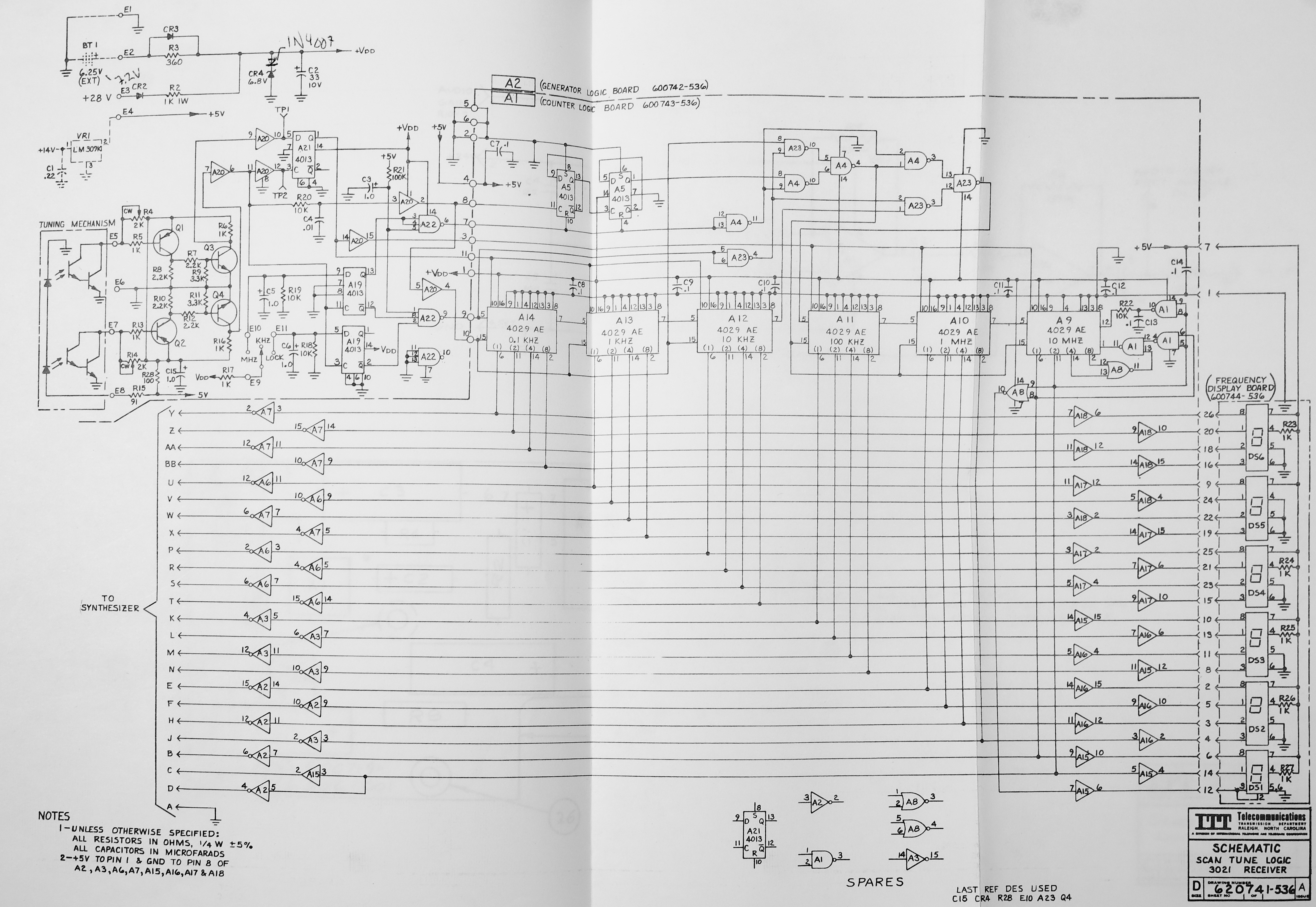
The schematic of this is shown below (right click and open image to view full resolution). The principle of operation is described in the manual pages 4.17→4.20.
To show the operator what frequency is tuned, a 6 digit 7-segment display built from HP 5082-73xx series BCD displays is used. This display is quite nice and was retained for all future upgrades. As seen above the displays are wired to the exact same signals as the synth.
Replacement
This card was the first to be replaced, and below is a picture of the completed assembly before installation.
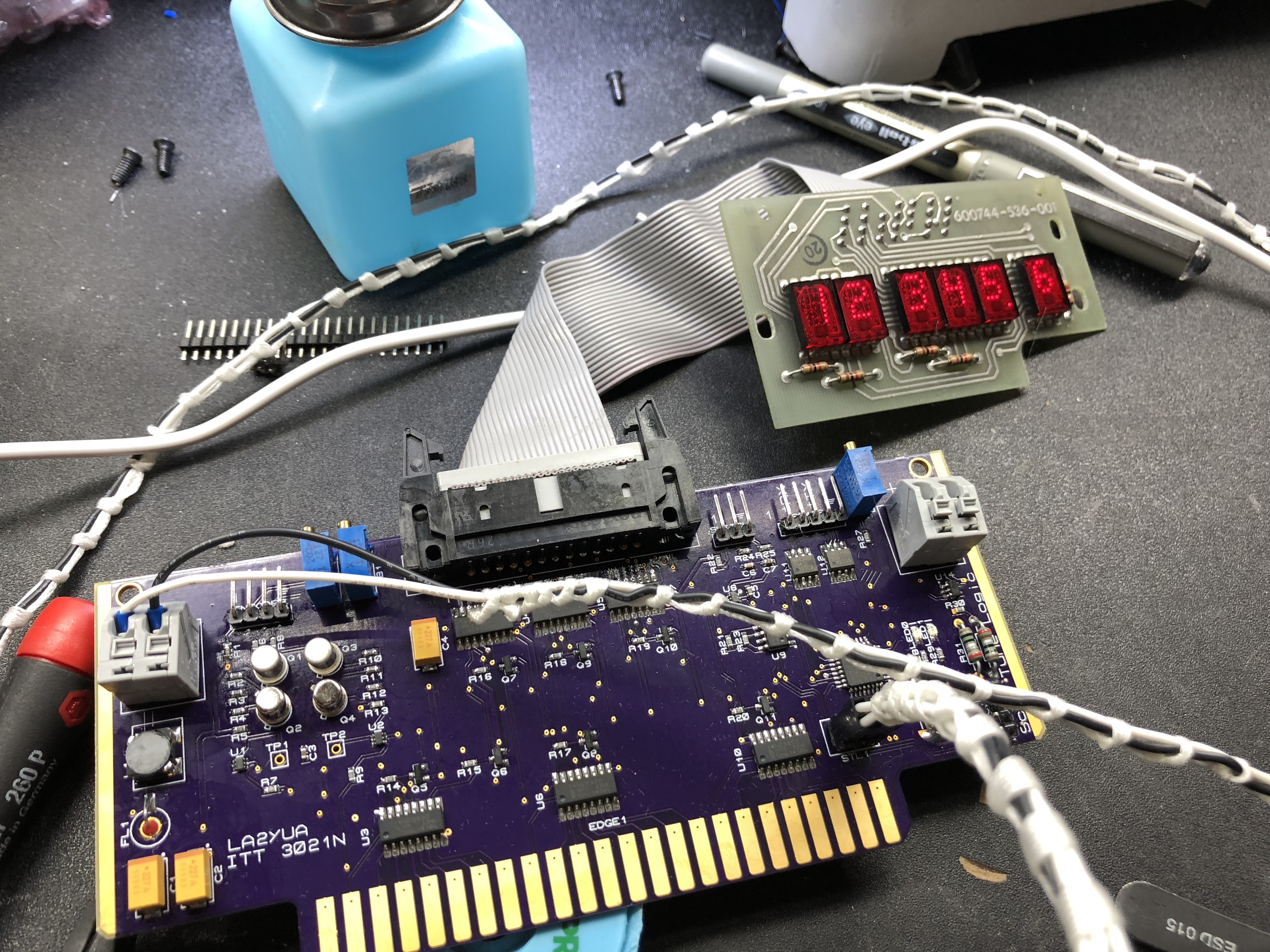
The original display connection was retained, and it plugs into the same back-plane connector as the original STL.

This design uses a STM32F030 MCU to read the quadrature encoder (using the same circuitry as the original), this is then counted using one of the hardware quadrature decoder timers. The frequency is then output to two shift registers, one going to the display and one going to the backplane (this means that the display can e.g. have leading digit blanking).
Obviously the original switches are also read in, and used to determine how fast the counting happens. The readout of the chopper is done in a very fast main loop, and the system can update the outputs at greater than 1 kHz rates, making it a decent emulation of the original discrete circuitry.
Once the tuned frequency has been stable for around 0.5 second or so, the current frequency is written to an F-RAM IC along with a CRC. F-RAM memory has almost infinite write cycle tolerance and high speed, so storing the frequency can be done quickly and as often as desired. On startup this is read and verified (10 MHz is set if an error occurs). I've used F-RAM chips for this type of storage in a wide range of projects since this.
I also replaced the original optical encoder at the same time, and I selected a 400 count industrial encoder instead. This was done since the original encoder had very worn bushings and wasn't very well balanced, meaning it either had high friction, or it would tend to rotate to some minimum energy angle when released if it was lubricated.
Since the new encoder is much higher count than the old one, the MCU divides down the count from the new encoder, and also implements some hysteresis on switching to avoid rapid toggling between adjacent states.
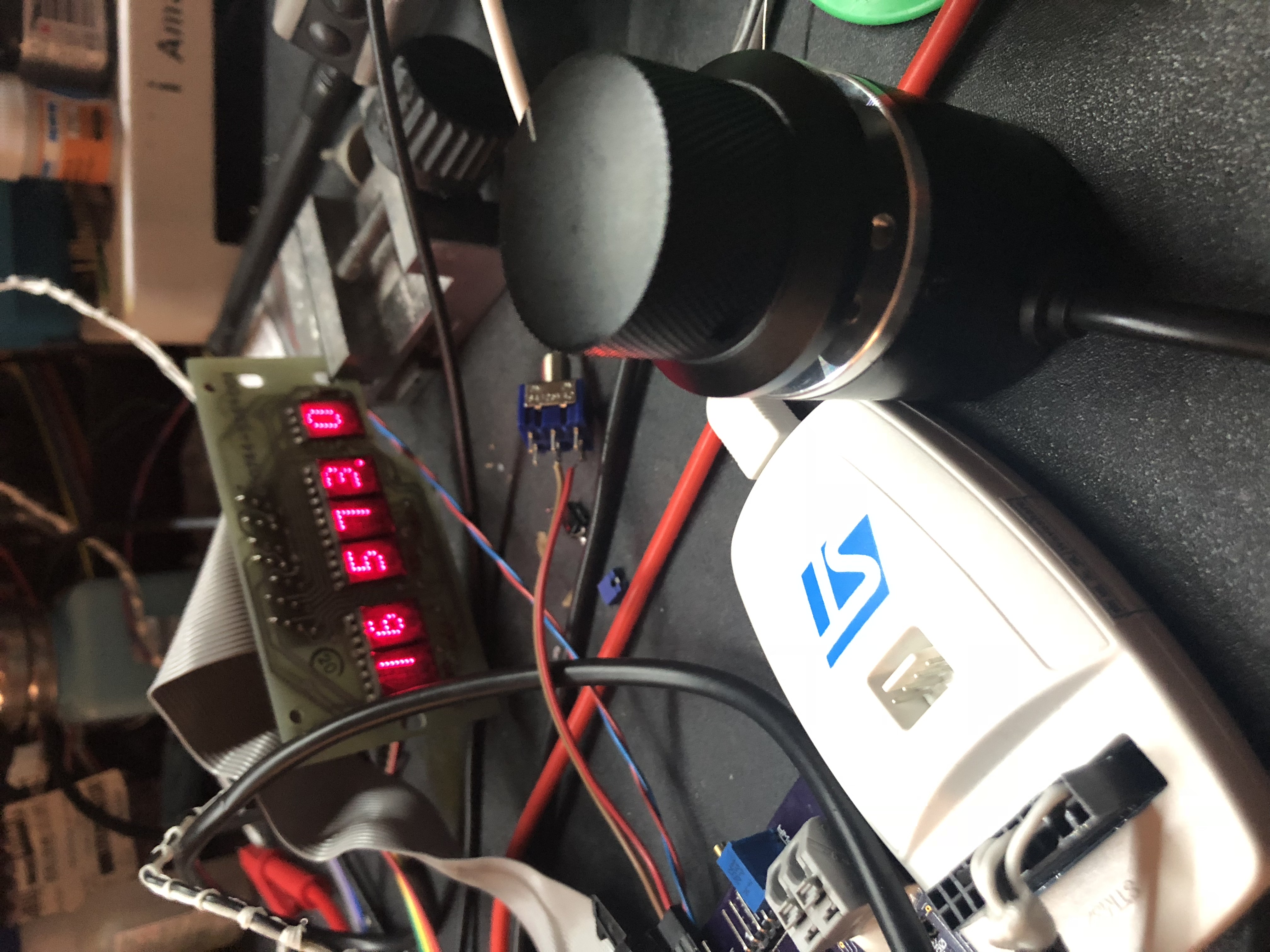
The new encoder will produce a higher pulse rate, and dropping pulses would be unacceptable, so a torture test was introduced:
After some testing I found that by basically snapping your fingers on the knob (or flicking it) reached a peak RPM of around 2-3000, so this was set as the target.
If digital or analog circuitry is too slow then exceeding a critical rate will either make the system stop detecting inputs, or in some cases even go backwards.
The industrial encoder has a 6 mm shaft instead of a 1/4" one, so brand name Koptan tape was used as a shim to fit the old knob. This encoder turned out quite well, and has not given me any issues since.
The new STL card also includes a linear current regulator that controls a LED light placed above the S-meter, to illuminate this appropriately.
Later Modifications
The card was later modified to output RS-485 instead of RS-422 (the card has a serial output for remote control, didn't mention that).
In addition, the later replacement of the original synthesiser could have eliminated this card, but I decided to modify it instead.
The modification entailed moving as many of the direct wired connections as possible to the backplane connector (everything except the display cable). The backplane BCD output was then removed, and the SPI signals going to the shift registers were instead routed directly to the backplane and to the new synth.
This way the synthesiser frequency update goes into a CPLD in the new synthesiser instead of the original shift registers. The CPLD then signals the microcontroller there to update the frequency.