
The NAGRAFAX
The NAGRAFAX is an early 1980's weather-fax printer, sold as a kit along with a weather-fax FM receiver and intended for marine use. I picked up this unit for $10 at a local auction (first and only offer, surprisingly).
Overview
The NAGRAFAX was manufactured by Swiss company Nagra Kudelski (I believe these are two separate companies working together). Nagra is fairly well known for making tape machines, and I guess making a fax machine is not too big of a stretch.
The manual indicates this unit entered the market in 1980 (Crypto Museum says 1977), and was likely sold for some time after. Surprisingly Nagra still provides schematics and mechanical alignment information on their official website, though the quality of the scan is not exactly great which made some things hard to work out.
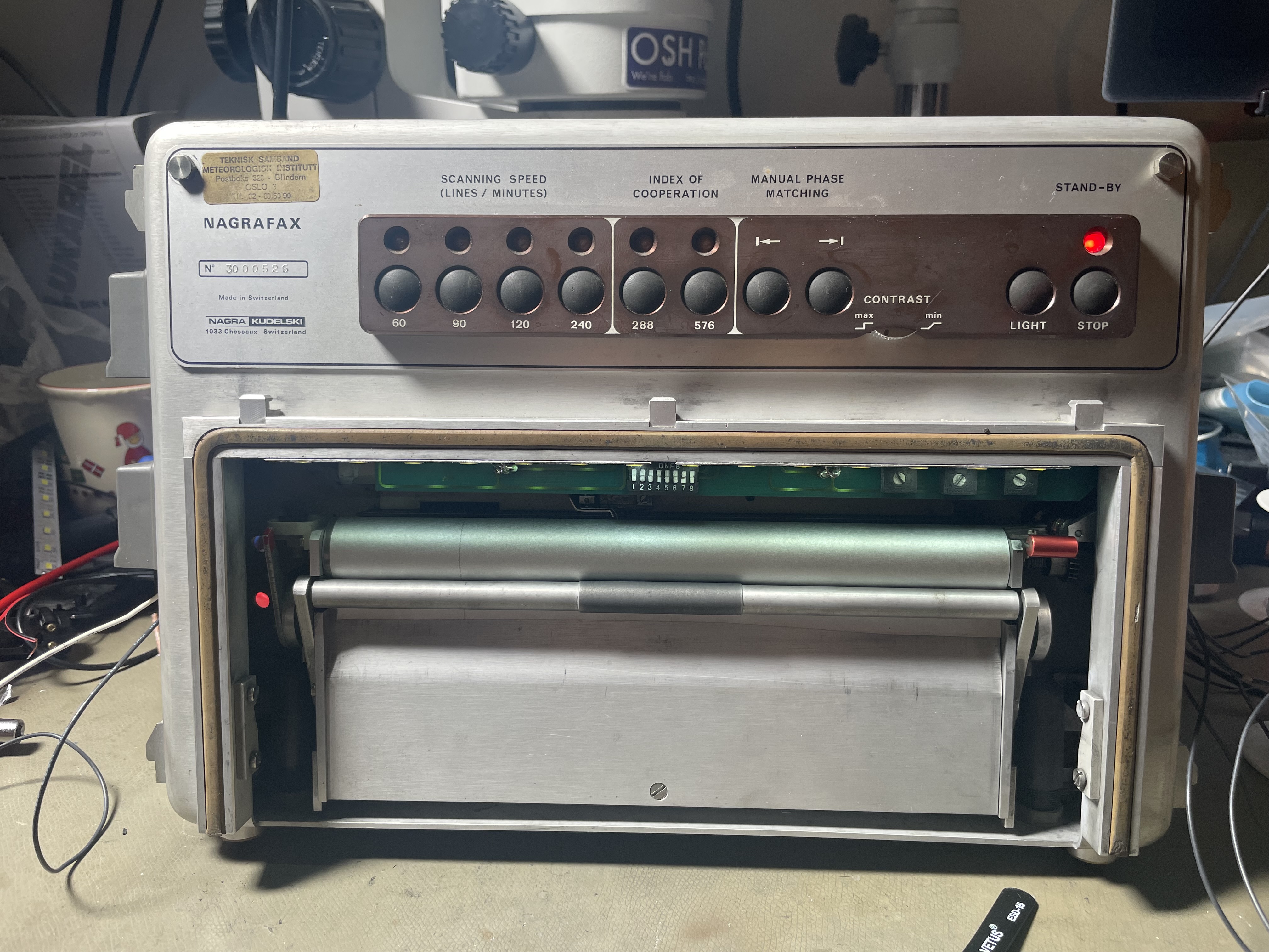
Above the machine is shown without the plexi-glass front cover, and with a modern LED strip replacing the two light bulbs that would normally (poorly) illuminate the printer area.
The fax machine is housed in a two-piece aluminium chassis with various gaskets. I/O is via two 9-pin D-Subs, which have port covers providing some weather protection.
The power supply for the fax is approximately 13 V and up to somewhere near 30 V, making it easy to power. The current consumption in operation is typically less than 200 mA average at around 14 V. The paper advance stepper motor pulls a further 300 mA or so when active.
This fax can still be used with a suitable demodulator and radio in 2023, and for European users DWD (Pinneberg, Germany) and GFA (Bracknell, UK) are still on the air every day on multiple HF frequencies.
The specific unit was the property of the Norwegian Meteorological Services communications department. From what I have learned, these units were installed at various sites such as airports which had use for meteorological data. In this use case they were connected to telephone lines rather than radio receivers, and provided with video data that way.
Table of Contents
Principle of Operation
The fax machine was primarily meant to be used with a "FAXDM" HF/VLF receiver, which was a crystal controlled receiver that generated the video signal for the fax, as well as providing some signal monitoring capabilities beyond just looking at the print.
Unfortunately this receiver was not available.
Printer Mechanism
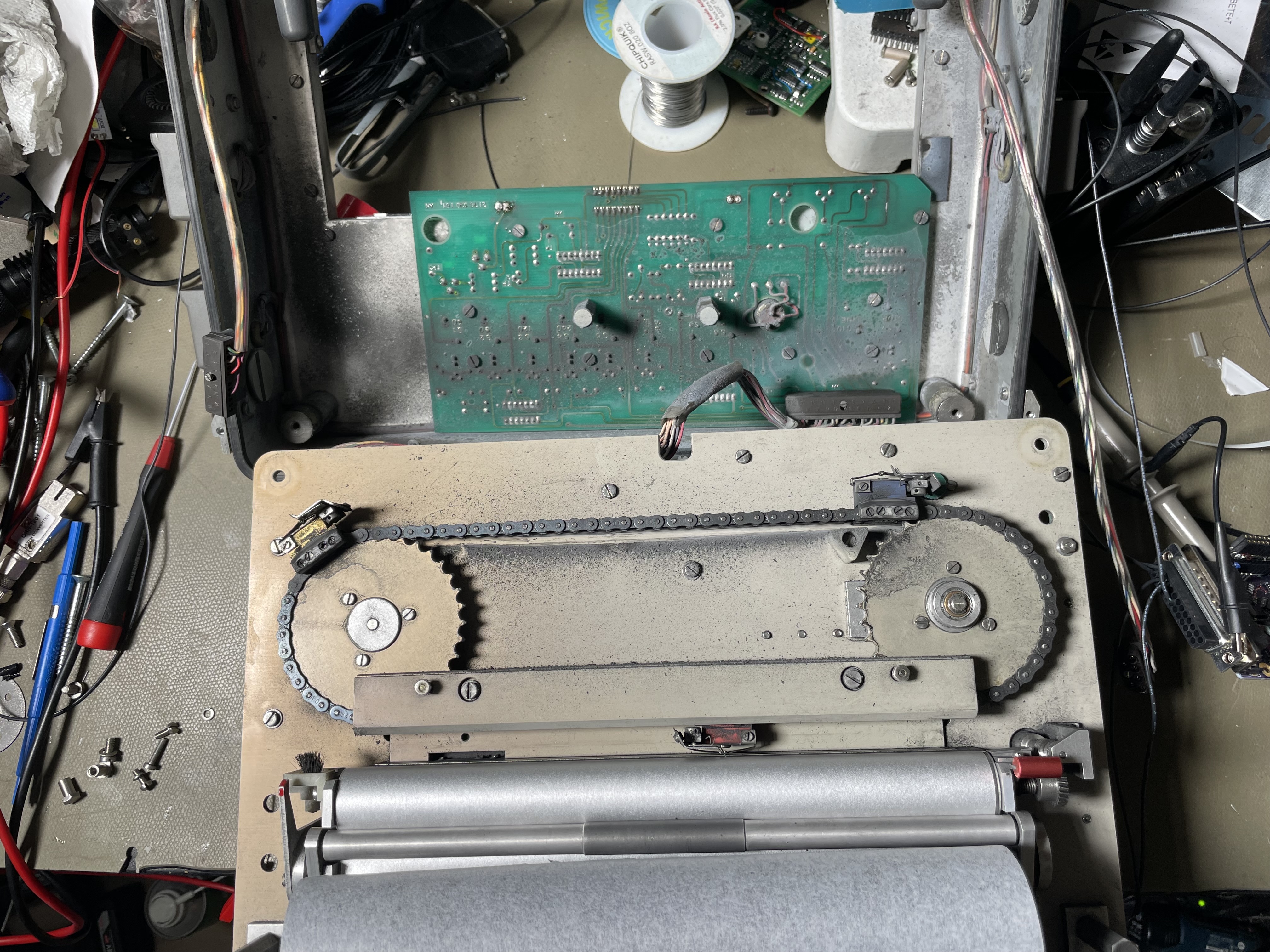
Above the print heads and drive chain are shown, the mechanism is fairly unusual these days. The printer uses special aluminised paper, which seems to be a laminate of aluminium over dark paper, not dissimilar to old school candy wrappers.
The printing mechanism selectively darkens the paper by striking an arc between the print head and the paper, this vaporises the aluminium layer, exposing the darker paper below. This paper seems to be fully waterproof and no ink/toner is required, both would be a benefit when operating at sea.
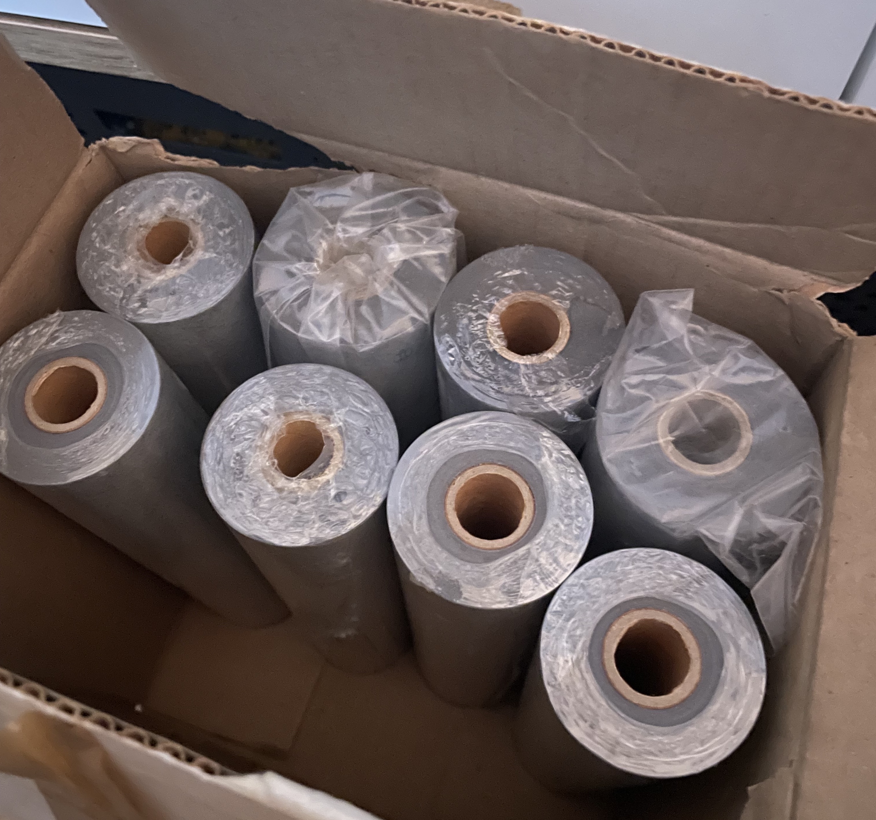
The printer came with some spare paper, I don't know if it's possible to get any more.
This process deposits vaporised aluminium all over the machine, which made it quite messy after probably 10-20 years of operation seemingly without any cleaning. Surprisingly this dust doesn't appear to be conductive, so even with the electronics covered in dust they still worked.
Control Circuitry
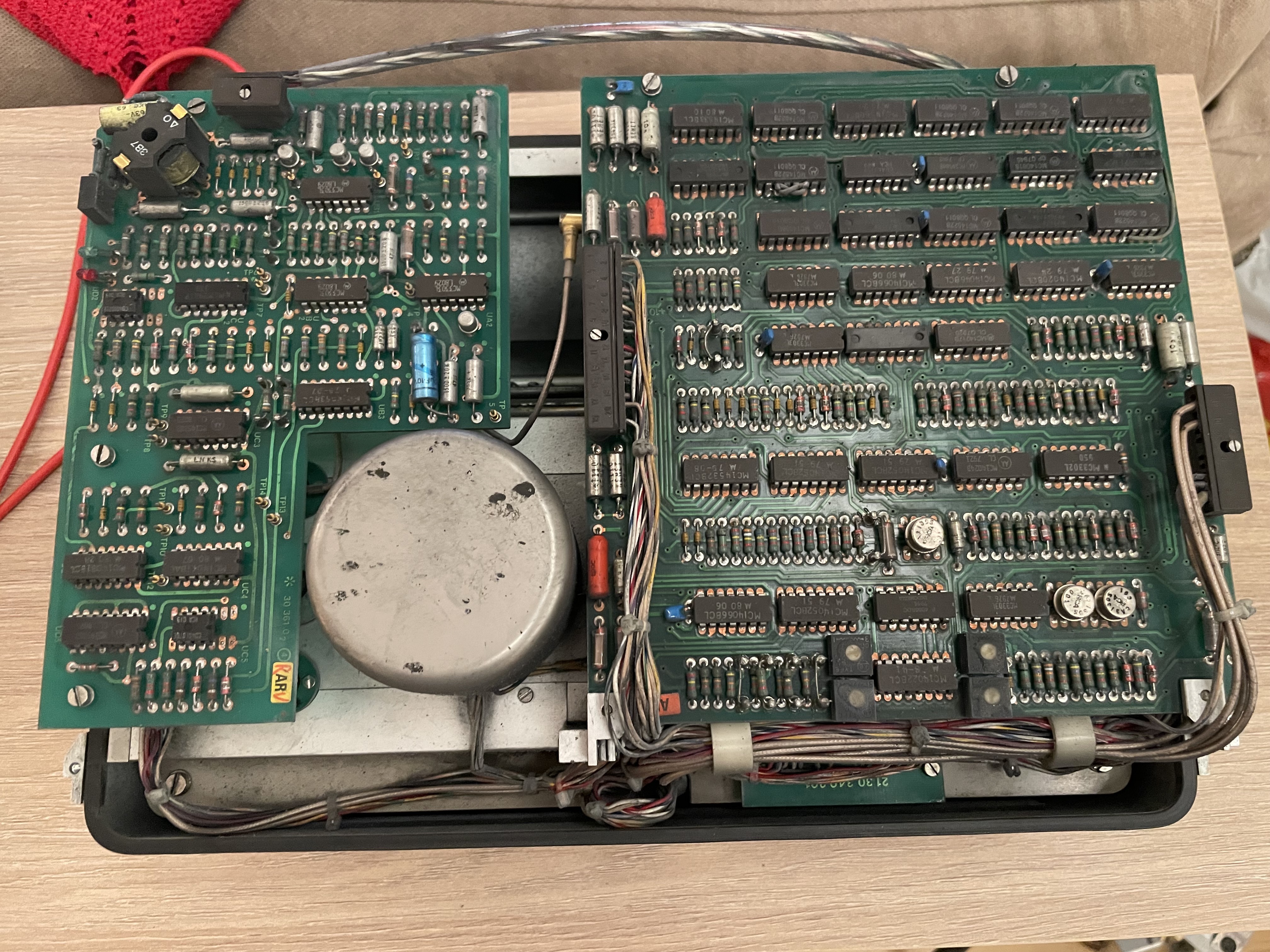
Above the rear of the machine is shown after some compressed air removed most of the dust. The right-most circuit boards are stacked and hinged allowing for service. They are documented in the manual and contain the video amplifiers, servo drive, and logic state machines.
The logic seems to be entirely 4000B series running at 10 V, in mostly ceramic packaging indicating high cost. The left-most circuit board is discussed below. Capacitors appear to be almost exclusively military-grade silver-tantalums, which are not great capacitors but as far as I know these are not known to fail.
Weird connectors are used, they use a retention screw with micro-D like contacts only much much bigger, and the PCB side of the connector is simply a set of sockets with no shroud.
The center motor is the chain drive motor, which is a standard brushed DC type. There is magnetic tachometer feedback from the chain drive, which is used to close the speed loop of the receiver. A stepper motor is used to drive the paper advance, and there is a paper-empty micro-switch that disables the machine if it runs out.
I don't fully understand all the circuitry, but it seems the chain speed is crystal controlled through some complex circuitry. This circuitry presumably ensures that the scan speed is well defined, and implements automatic phase control, which means that it tried to "center" the image based on some initial synchronisation pulses. The three potentiometers on the front do not appear to be in use when the crystal synchroniser is enabled, and I'm not sure exactly what they would do in any case.
Note that WEFAX does not use continuous synchronisation, the printer has to run at the right speed, and it's not uncommon to see the image "slant" due to small frequency errors. The benefit of not synchronising continuously is that no matter how poor the signal is it can't lose what it doesn't have.
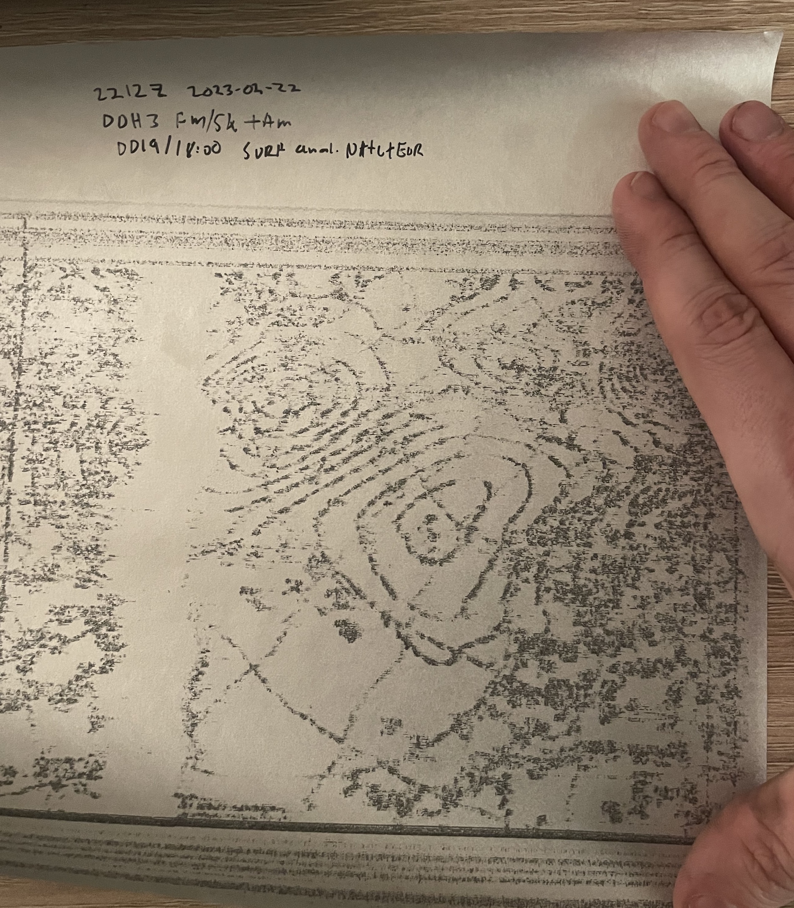
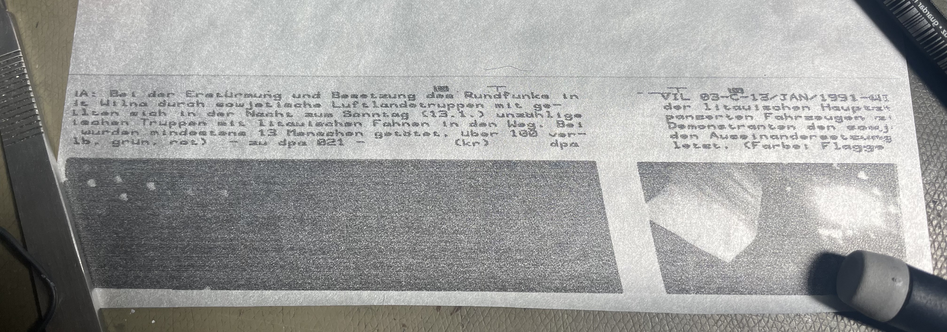
The above image shows the first real-time on-air fax I received, the signal quality was not particularly amazing but the image can clearly be seen even if the text can't be easily read. This particular image was received using my 3021N receiver and the optical Mini-Whip, received from DWD at 3855 kHz. I have found that 7880 kHz is a better bet during the early evening.
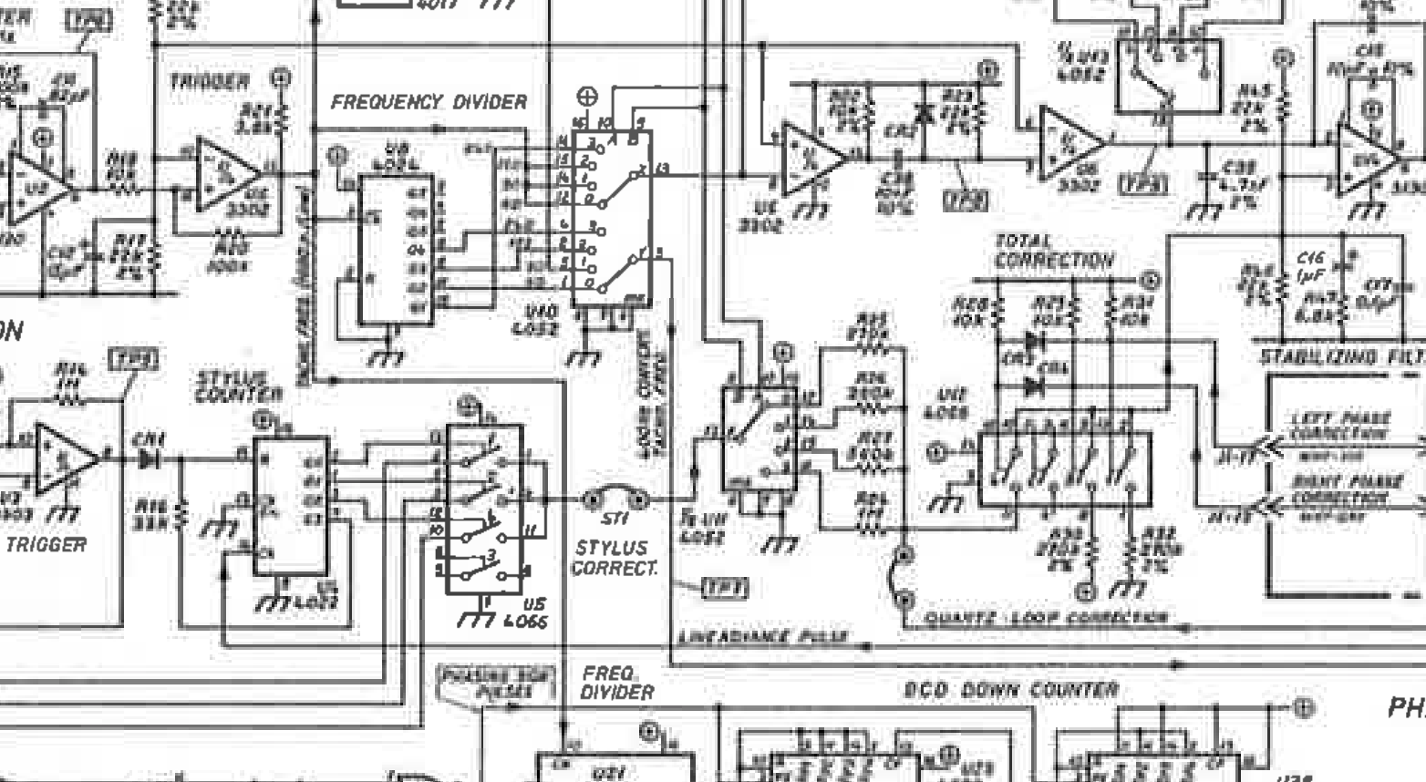
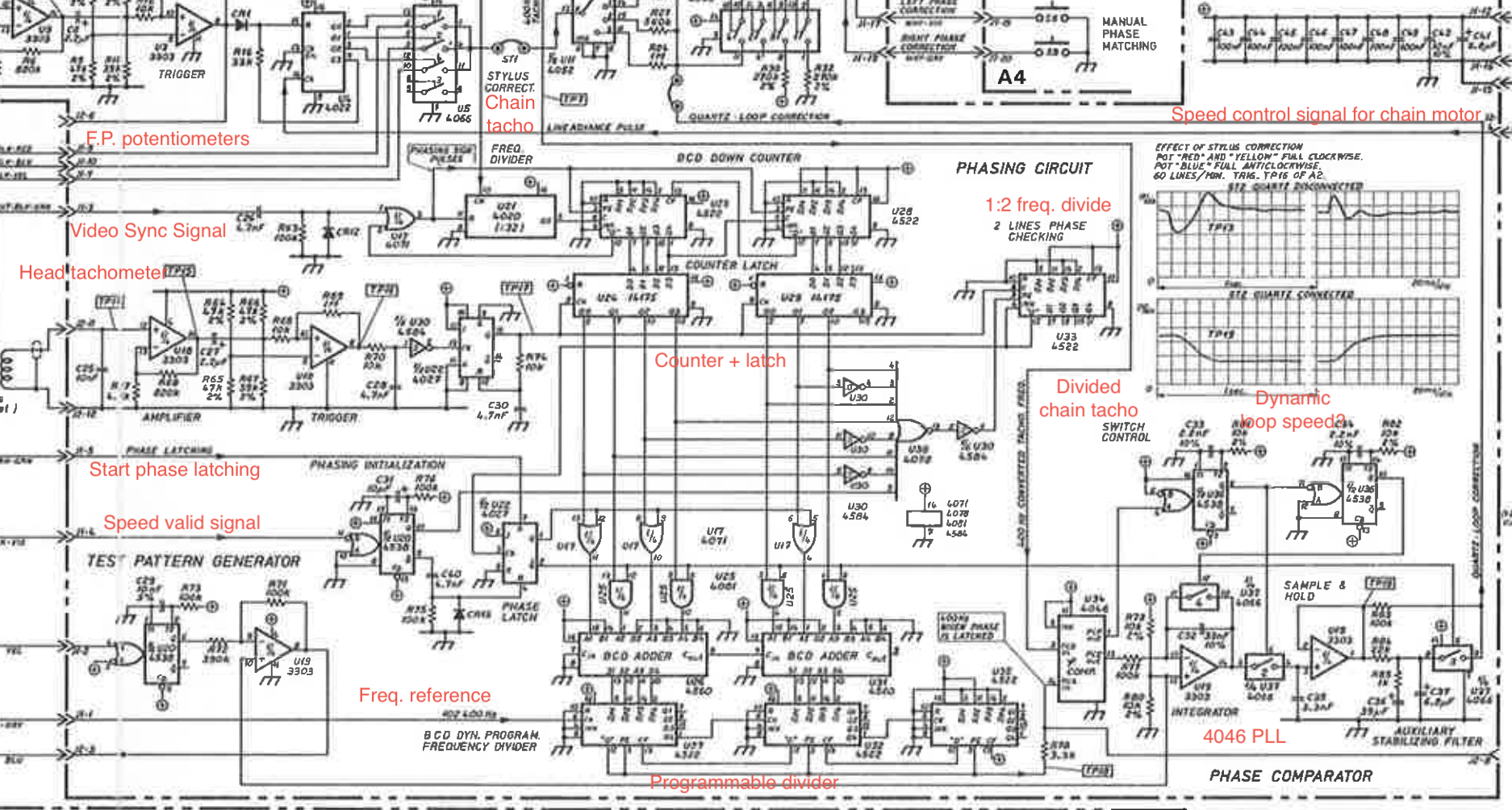
Speed Detect
After receiving the start tone (or if manually set to an IOC), the fax will start looking for phasing pulses. The fax signal will stay at black for some time, sending white pulses during the blanking interval.
The fax appears to perform an automatic alignment of speed based on this signal, the circuitry is not very well explained but I think I have a story here:
- Initial search, speed is minimum (no speed control signal set)
- An operational amplifier circuit thresholds the video signal to generate an external phasing reference
- The period of these pulses is measured in a 4 bit counter circuit relative to the internal crystal oscillator
- The output is routed to a set of digital comparators
- When one finds a match the associated speed is set unless the found speed is inhibited
- The speed control signal bus is then valid and the process can continue
- The counter circuitry is stopped if any speed signal is set
- The speed control bus is used in several places around the fax, especially in the scan motor drive system
- The circuitry is shown below
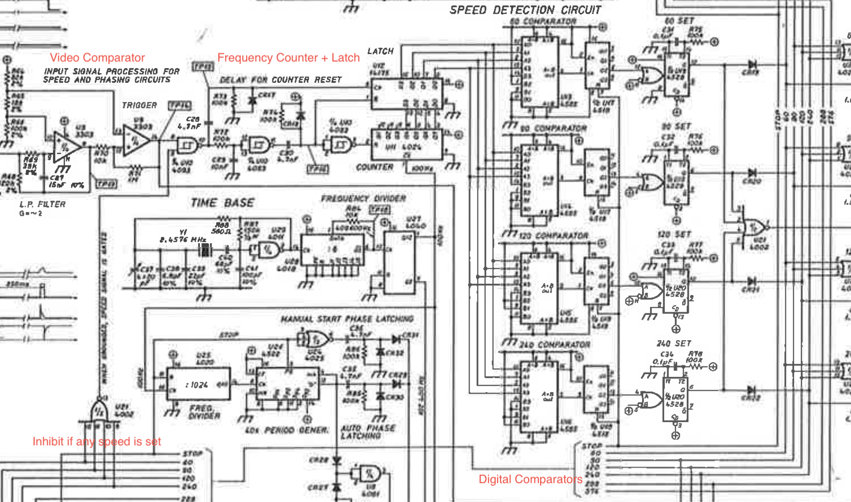
The circuitry to the bottom middle generates a control signal that enables automatic phase alignment of the receiver. This circuitry is activated when the STOP signal is released, which occurs e.g. when a start tone is generated, or when manually started.
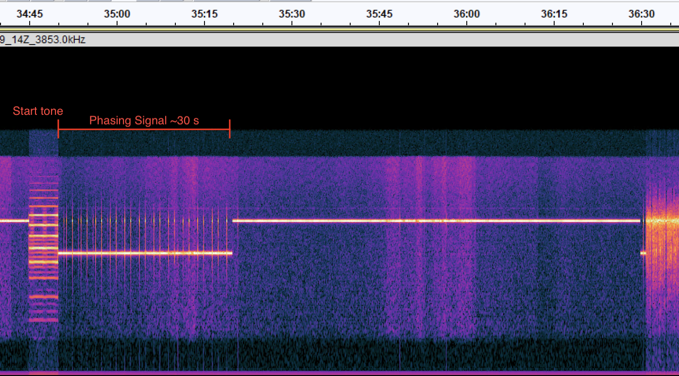
Below is a typical 2023 transmission, showing the phasing sequence lasts approximately 30 seconds. The fax seems to be configured to turn off the phasing system slightly before the 30 second mark, at this time whatever phase it locked to will be used for the remainder.
Phasing & Speed Control
The system that controls automatic phasing and crystal regulated speed is… complex. At the time of original issue, I had not yet worked out all the details of this circuitry, but I had worked out that the automatic phasing system was not functioning in my unit.
Measurements on this system will be the subject of future work to try to make the automatic phase alignment actually work reliably, since right now it seems mostly useless.
Controls
The front panel controls are limited to a set of speed and IOCs (Indices of Compliance), manual phasing, illumination control, and a manual stop button. Modern red LEDs indicate the current state. A potentiometer controls the video contrast; I can't say that I've found it particularly significant.
To manually start, select an IOC, then optionally select a speed (not required if the video input is in the initial phasing stage).
DIP Switches
The DIP switch functions are listed in tabular form below:
| Number | Controls | Comment |
| 1 | Phasing signal write suppressor | When 'On', the phasing is unblanked |
| 2 | Internal test pattern generator |
Requires switch 1 to be 'On'. Generates a set of vertical stripes across the image (using an internal pulse generator) |
| 3 | Disable 60 LPM | |
| 4 | Disable 90 LPM | |
| 5 | Disable 120 LPM | |
| 6 | Disable 240 LPM | |
| 7 | Disable IOC 288 | |
| 8 | Disable IOC 576 |
The disabling of modes is likely meant to be used to prevent false-detection of modes in automatic operation. I did observe it try to use 90 LPM for a 120 LPM signal in one case, and for most uses only one or two modes will actually be utilised. My unit came with 90 LPM already disabled, which suggests this was a common issue.
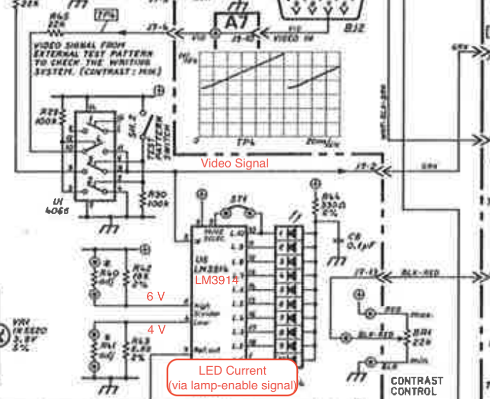
Bar Graph
My unit does not have the bar-graph, but this is shown in the available schematics. This was likely added in a later revision of the front panel PCB. I annotated this circuitry below, based on the hookup it appear to be intended as a tuning aid, showing the current video level.
It is shown in use in this video from 'The Fixman':
Printer Alignment
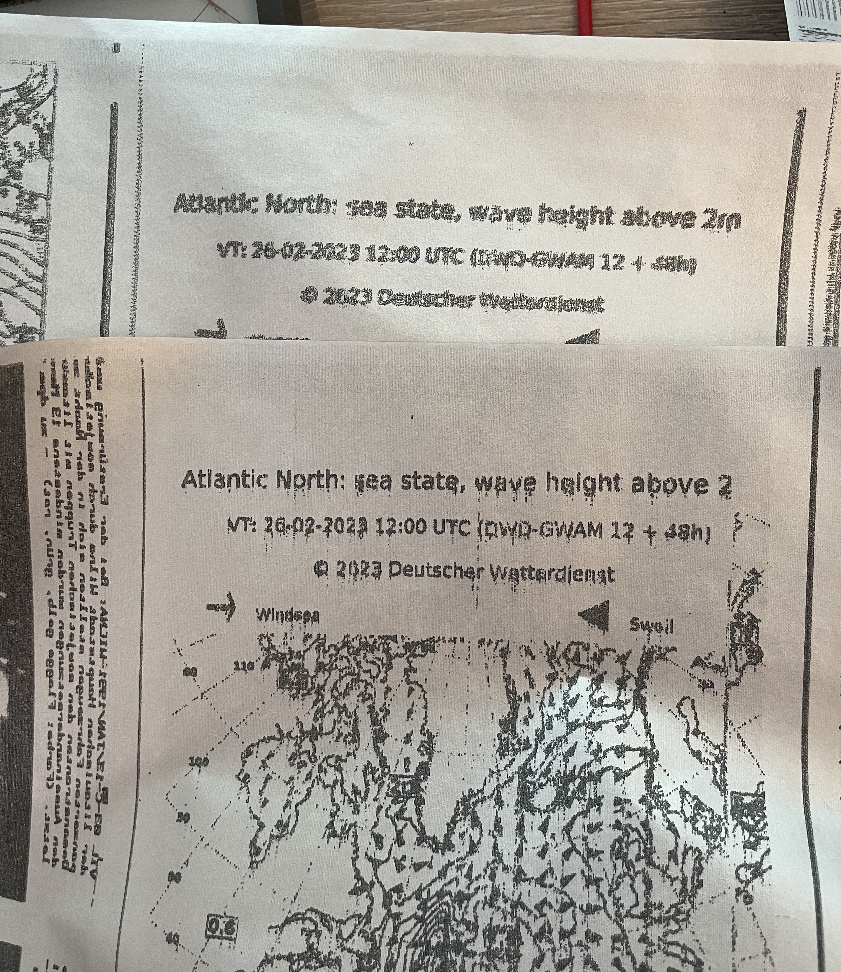
The internal test pattern generator is good for alignment of the print heads in the scan direction, run it at 60 LPM and you'll see if any heads are misaligned and note which head colour to adjust.
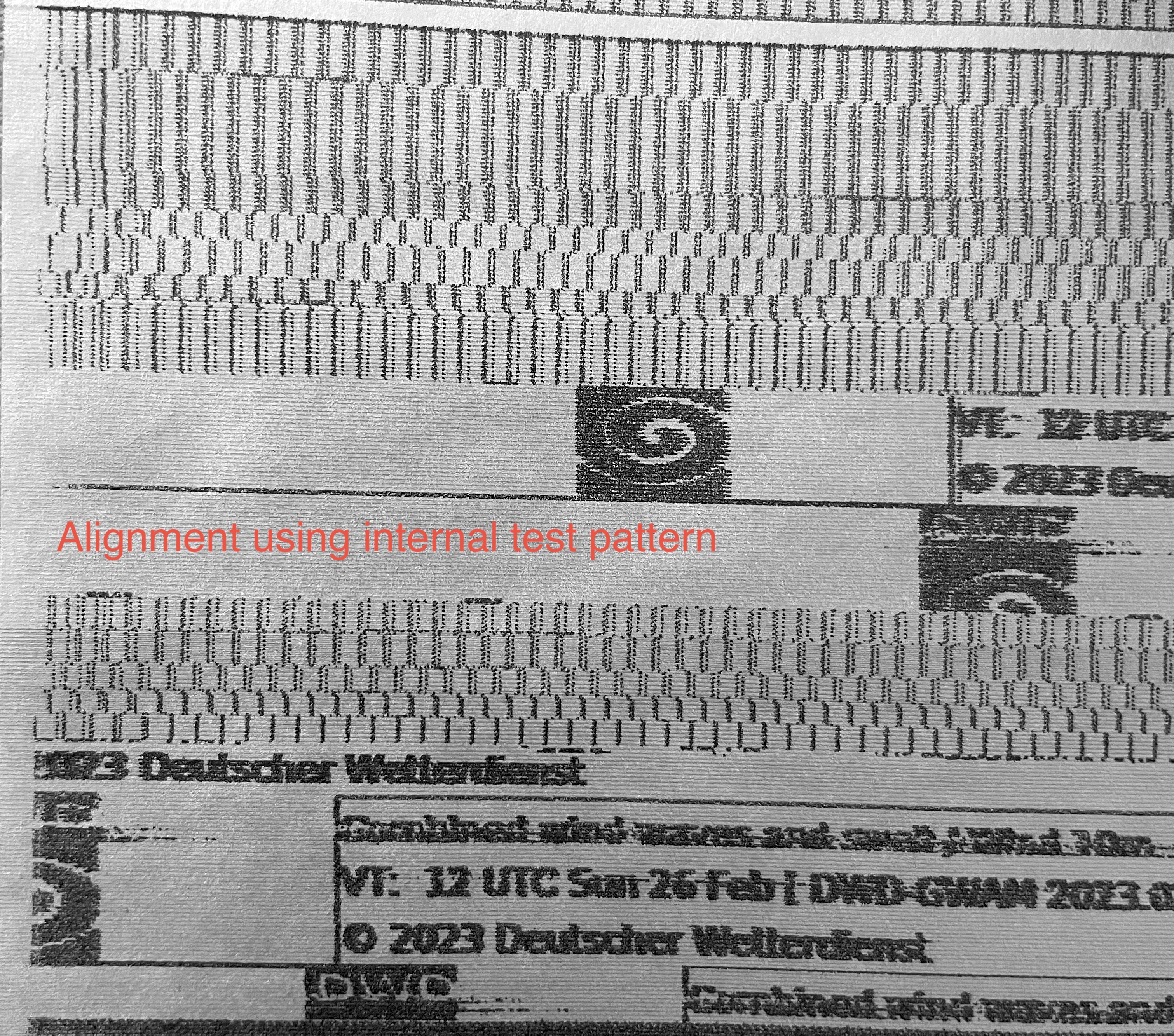
Above shows my alignment sequence, you can see the sequence, ending in a somewhat decent printout of of a DWD chart footer that I used as a reference test image.
The heads are coloured red, yellow, and blue. Alignment of scan direction error appears to be via bending the stylus with pliers, I couldn't find any better way of doing it. Perhaps as mentioned above, the stylus dynamic correction potentiometers are intended for this purpose? I didn't try this alignment method, but will investigate further in future.
See part 2, the potentiometers do affect the head-timing, so this is the preferred adjustment method.
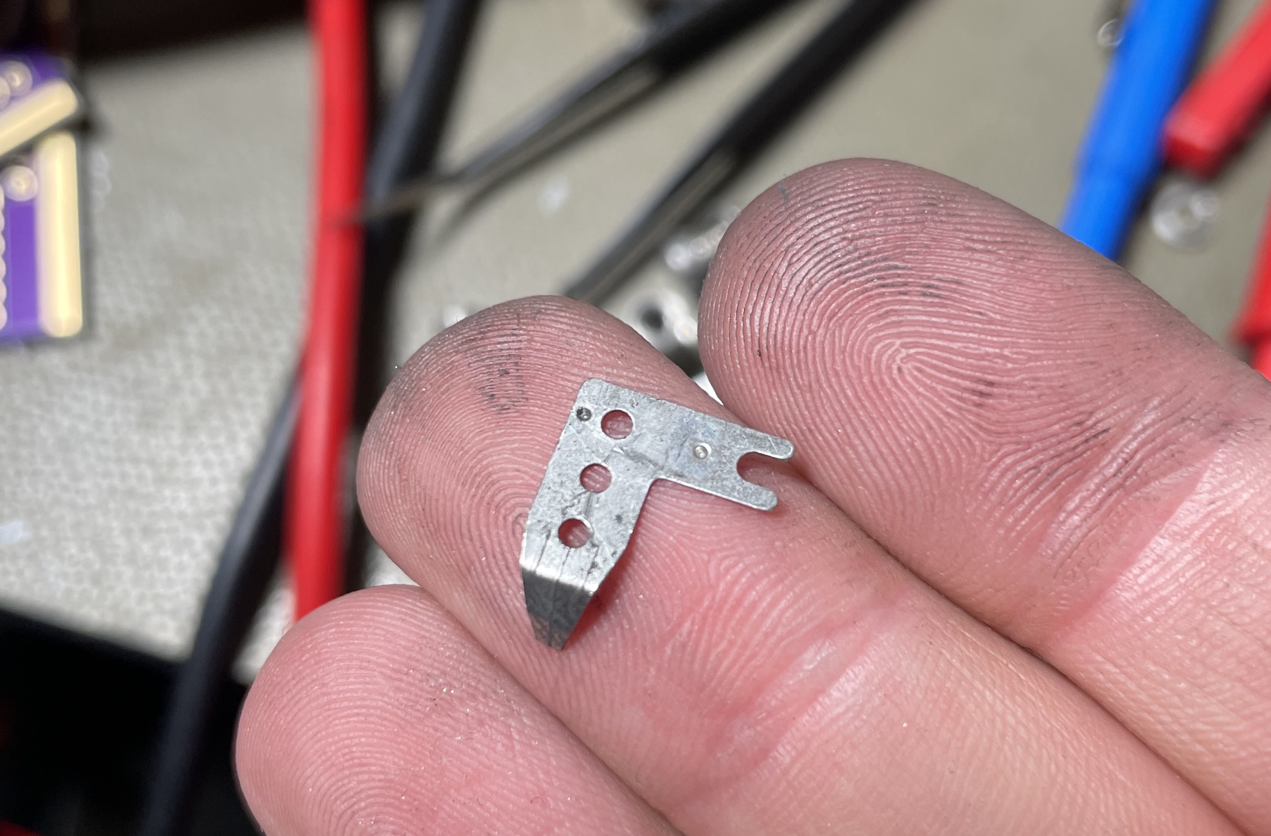
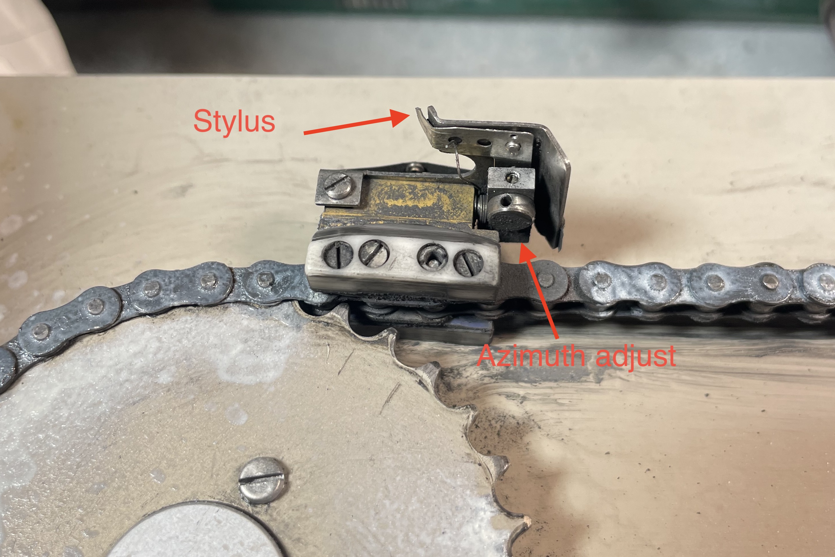
Below the key components of the head are shown, the stylus is retained by a small pin and a spring, it can simply be pulled off for replacement. The azimuth adjust is done by loosening the flat head set-screw, and rotating the shaft above it.
As received my unit had extremely worn down styles (styluses?) that were basically flats instead of points. Since Nagra doesn't appear to stock spares anymore, I ended up using a diamond cut-off wheel to "sharpen" them into new points. This procedure makes them a fair bit shorter, so I had to realign in the scan direction. Since the new points weren't fully on point I also did the vertical align, which went pretty well.
Above a comparison between unaligned and aligned quality is shown; the vertical striping was later improved further with a better demodulator design.
AM Demodulator
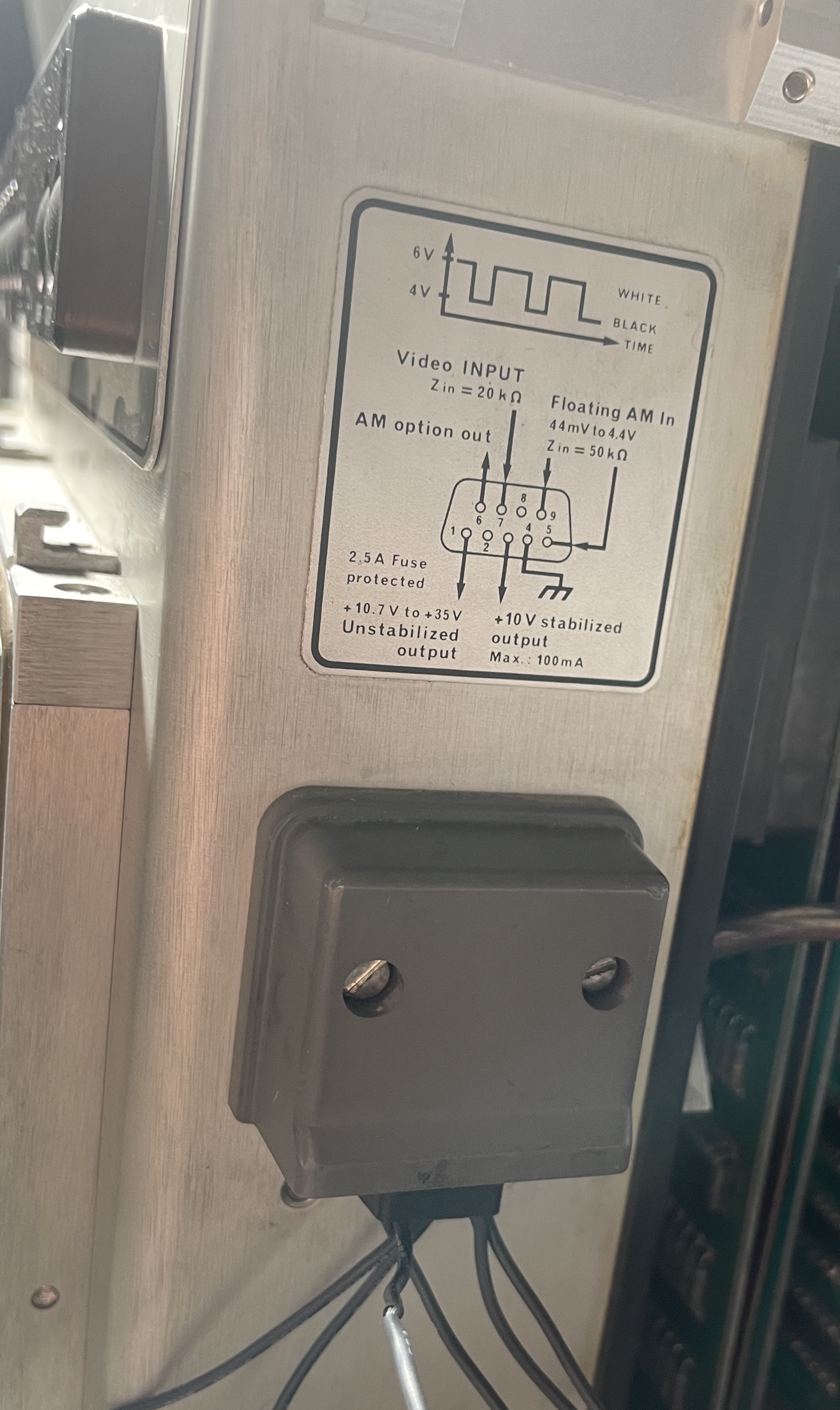
My unit came with what appears to have been a factory fitted optional extra board, and included a sticker noting that an internal (transformer isolated) AM demodulator was included. This suggests the unit was used with something other than HF WEFAX or similar, and I'm not entirely sure what that would be. The AM input can apparently have any center frequency between 1.5 and 5 kHz.
Above is the result of using the Twente webSDR FM demodulation mode, and feeding that into the AM demodulator. It looks awful, but this was the first comprehensible image I made. Feeding the FM signal into the AM card produced unreadable results, so it's clearly made for some other format.
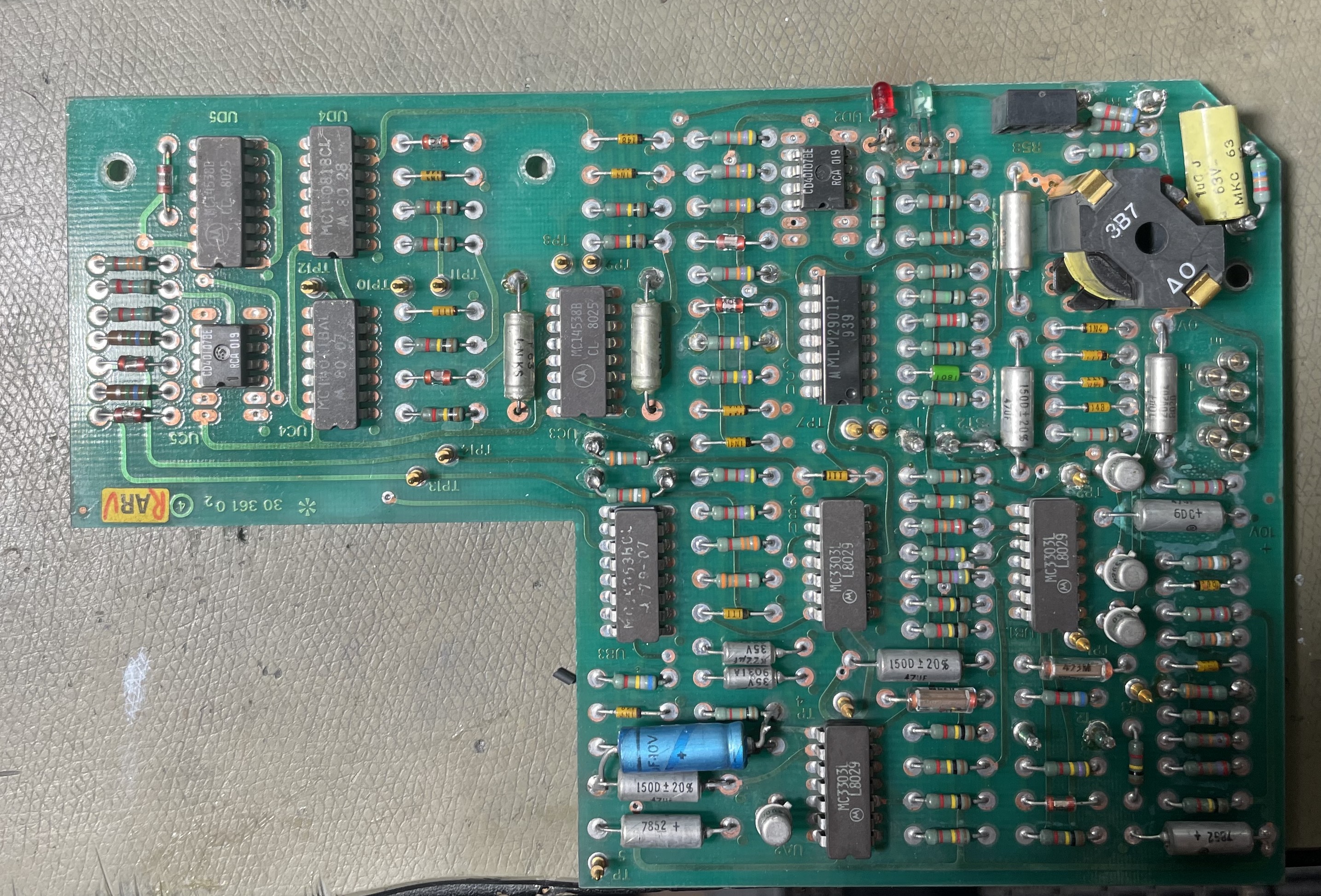
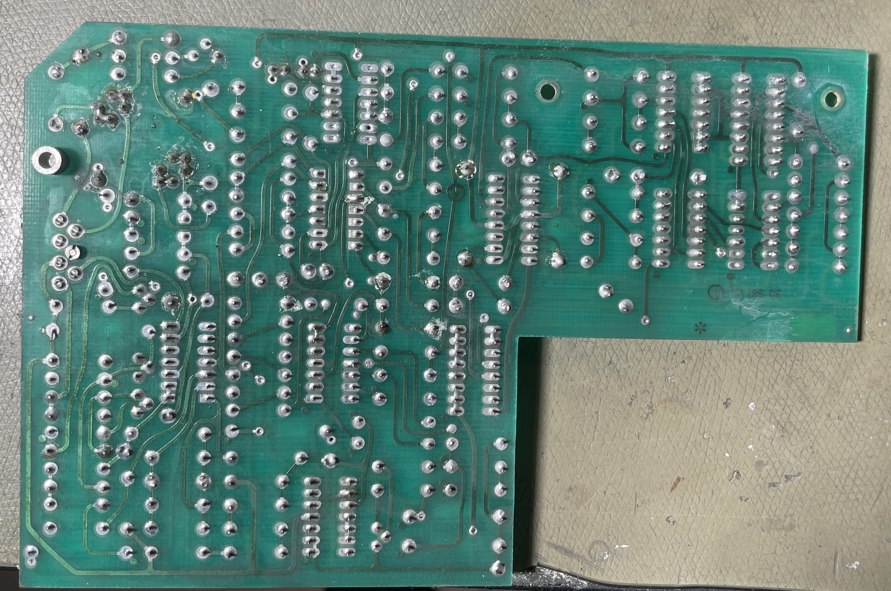
Below are pictures of the board, there are various test points, probing these I suspect the board implements a synchronous AM demodulator of some sort. This is mostly based on the fact that I found a recovered square wave carrier signal on one test point.
The ICs found include: CD40107 NAND gate, MC14538 monostable multivibrator (oscillators perhaps), MC14001B series logic gates, MC14053 analog switch (maybe a mixer), MC3303 quad opamps, and an MLM2901 (a LM2901 comparator?). The ICs are all dated 1980.
The two LEDs are automatic level control indicators indicating high/low AF levels, and there is a potentiometer accessible from the side which adjusts the output DC offset (i.e. image brightness).
Best guess would be it's a line type interface, it was probably connected to a phone line via some interfacing circuitry provided by the state telecom provider. As for why they would use AM instead of FSK, who knows. Probably comes down to cost.
The Nagra schematics don't mention this board at all, and from the way it was installed it looks slightly retrofitted, the board mounting is completely different from the standard cards and looks somewhat unsteady.
FSK & Video Format
The NAGRAFAX uses unusual but not entirely insensible video levels of 2 V p-p centered at 5 V DC. The video is positively modulated, so 6 V is full white.
The video is in fact analog, which surprised me. For weather charts a binary digital signal would suffice but the almost identical PRESS-FAX was used for both images and text, and I have printed PRESS-FAX recordings successfully with reasonable photography quality.
The NAGRAFAX supports analog video levels, but the video levels appear to be quantised to 8 discrete levels in the video drive circuitry.
The signal is conventionally transmitted as analog FM radio in a ~3 kHz HF channel. It is tempting to call this FSK, but it is as mentioned analog FM with some special characteristics. Current on-air stations use ±425 Hz deviation with positive modulation (and IOC 576/120 LPM).
Documentation suggests VLF fax transmission was done in the past (with ±150 Hz deviation). The only specific VLF transmitter I know of is CFH, Halifax Canada, but according to an article from MONITORING TIMES in 2011 these services have been shut down.
The bandwidth is limited to 3 kHz, and knowing the ~1 kHz deviation I figured 1 kHz of video bandwidth would be fine (following the rule of thumb ∆f+2fu=bandwidth). This certainly works, but the actual signal bandwidth is around 3 kHz or so, and the demodulator needs to support this to make finely printed text readable.
Some start/stop sine tones are normally transmitted, these are detected by the fax machine, and allow it to (in principle) operate unattended. I didn't have any false starts, but I found that when conditions were poor the machine often misses both start and stop signals, so I had to manually control this.
Lacking an application specific fax radio receiver, I did it the normal ham-radio way and use an SSB radio to offset-tune the signal. By convention the offset to the nominal center frequency is 1.9 kHz, though I went with a round 2 kHz because I'm special.
FM Demodulation in an ADAU1701
To actually demodulate the signal, I implemented an FM receiver in an ADAU1701 DSP board. This choice was driven largely by the effort needed to put a 4046 on a bread-board vs. using the ADAU1701 based board I had sitting around already.
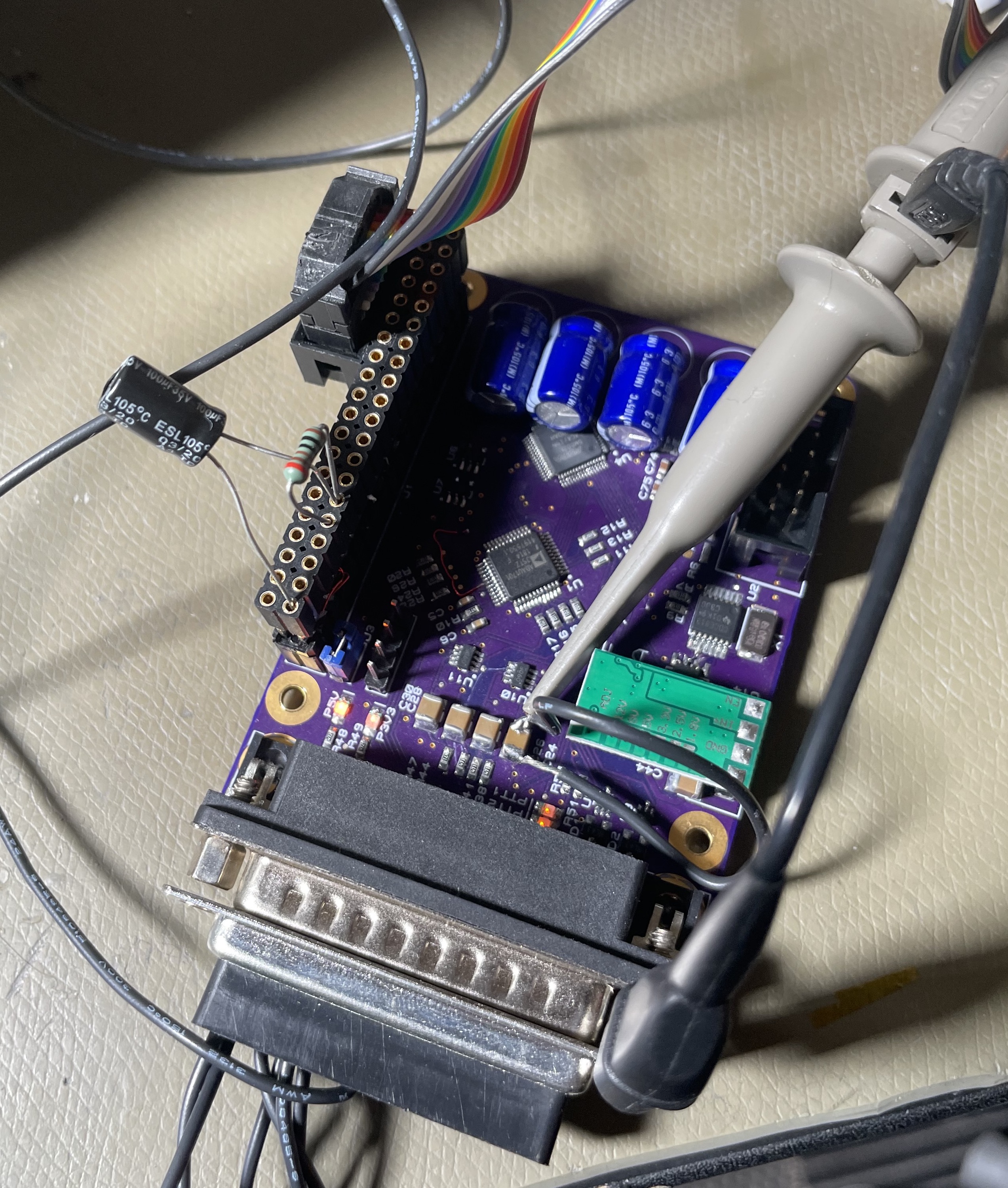
This board has a high-level audio output that was easily modified to operate DC-coupled. This way the DSP board could plug directly into – and be powered through – the NAGRAFAX accessory port without additional interfacing circuitry.
The demodulator design is somewhat novel, at least doing it this way in this DSP. Previously I had used this one weird trick to demodulate without atan(), but I found it hard to achieve the required video bandwidth and linearity needed for good quality prints.
My alternate design is not ground-breaking, but is simply a digital implementation of a quadrature tank demodulator.
The principle is to do the usual filter + thresholding of the FM signal, then we feed one branch into a 1st order all-pass filter tuned to the center frequency, and multiply this with the non-filtered signal.
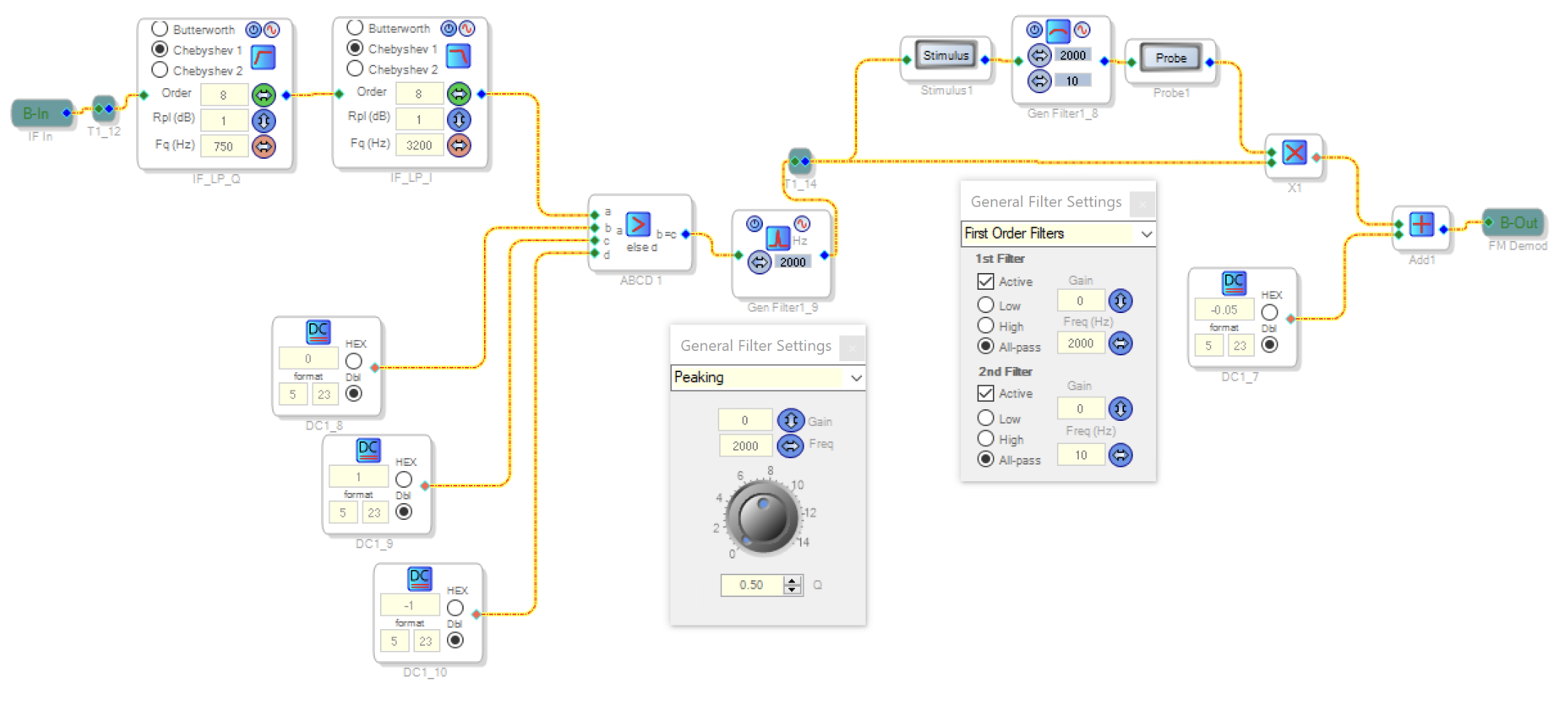
The all-pass filter will yield a phase shift proportional to frequency (leaving amplitude unchanged), and by multiplying the shifted and non-shifted signals, the D-C component of the result is the phase difference between the two signals. Two filters are used, the second filter provides a mostly fixed phase offset for convenience.
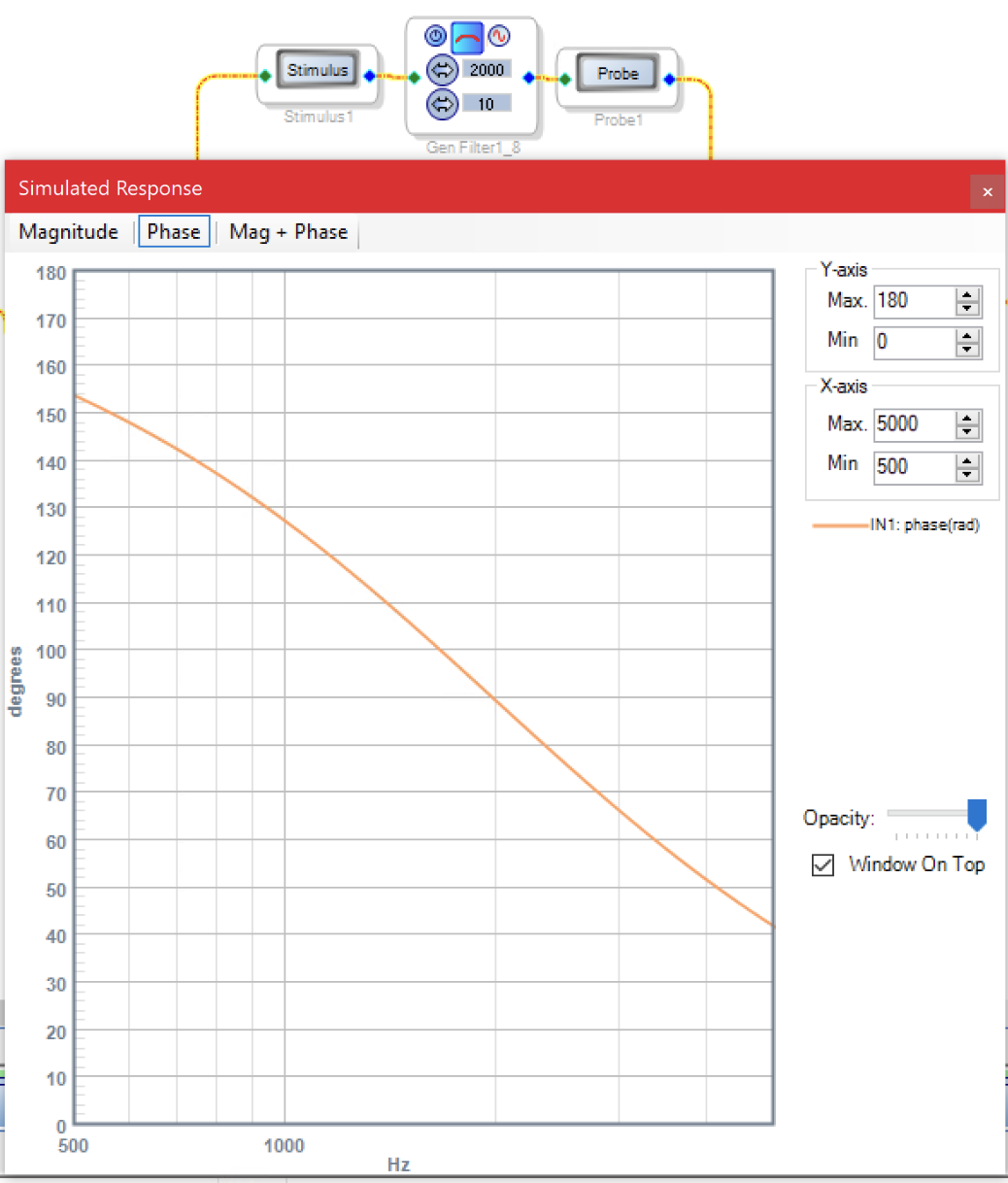
Since the phase shift shown above is proportional to and fairly linear vs. frequency, the result is that the output voltage becomes proportional to the signal frequency.
A low pass filter must be used to remove the frequency-sum term from the multiplication. I implemented this as a 10th order inverse-Chebyshev filter, which has somewhat poor pass-band linearity but extremely high stop-band attenuation. This allowed me to place the cut-off very close to the harmonic contents.
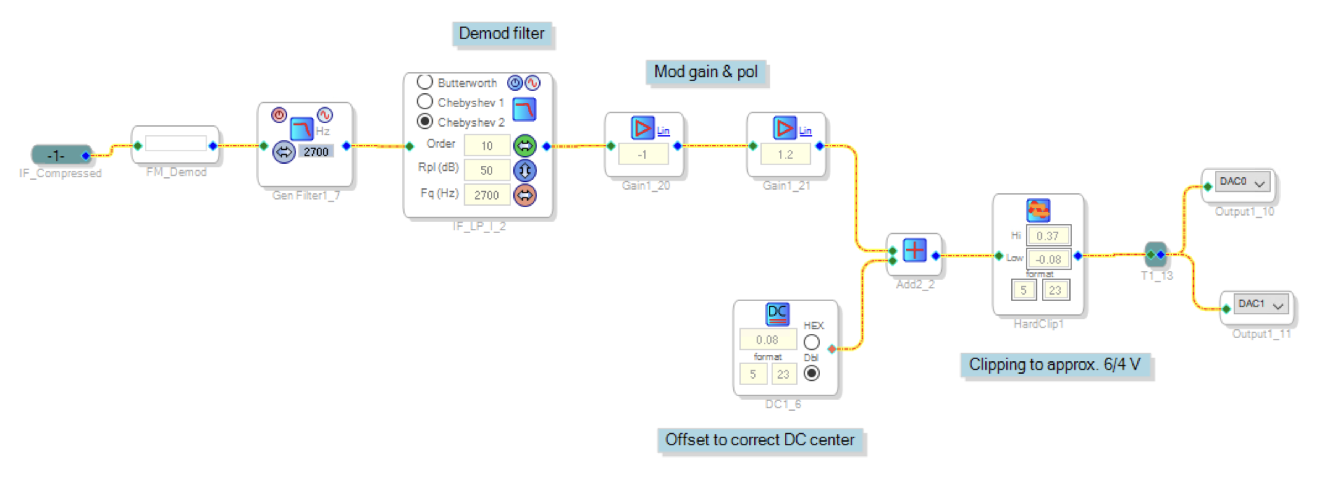
The nominal usable bandwidth of the demodulator is limited by 2⨉f_l where f_l is the lowest input frequency of the FM signal. A future improvement could be to mix the 2 kHz IF to a higher frequency before demodulation to move the sum frequency further away from the pass-band.
A modification to the basic scheme was implemented, where I placed a 2nd order low-Q (~0.5) peaking-filter tuned to the center frequency between the thresholding and the actual demodulator core. This seemed to improve the effective bandwidth of the demodulator, and I suspect that in practice this cuts out a lot of the lowest input frequencies, alleviating the frequency sum problem mentioned above.
This demodulation scheme was quite easy to set up, is relatively efficient, and with some tuning it significantly outperformed the more complex atan()-less solution linked above. It should be noted that the fixed point processing of the SigmaDSP may have played a part, and that this demodulator does not need to be particularly linear, only particularly fast.
webSDR Playback Woes
The original Web SDR (The Twente!) has some practical issues with doing real-time radio fax reception.
The real-time playback uses buffers, and I found that the sample-rate of the computer I was using was almost certainly slightly off from what the webSDR service supplies.
This lead to frequency "hunting" during playback, the audio would normally e.g. play slightly too fast. This will lead to buffer-underrun at some point, so when the browser starts running out of samples it slows down (probably down by '1' sample rate unit).
This slower unit is too coarse though, so then it starts filling up with excess samples, and it goes up '1' sample rate unit again, and now it's too fast again!
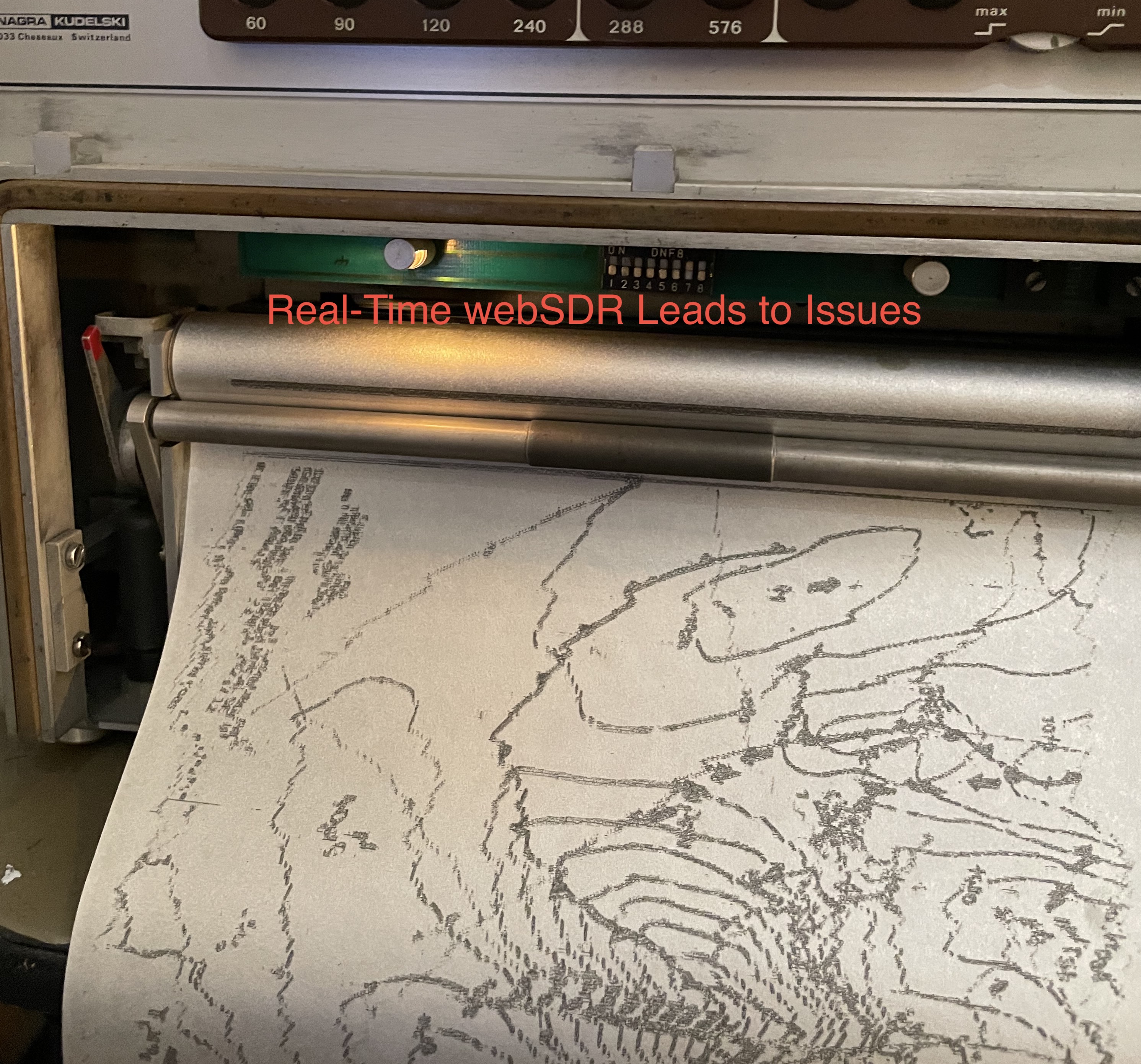
Radio fax doesn't use synchronisation pulses per line, the transmission is "phased" on startup, either automatically or manually by the operator. Once this is complete, the fax machine runs at whatever rate it's been calibrated to (under crystal control). In the case described above, this leads to very obvious steps in the horizontal alignment of the image, and this case was pretty extreme.
Ordinarily this error would simply lead to a slanted image, which is normally acceptable if annoying, and this could be calibrated in the fax machine if it were a recurring issue. An example of a slanted image is shown below, from a PRESSFAX recording.
The good news is that the recording functionality of the Twente webSDR works beautifully, supplying glorious uncompressed wave data that can be played back at a steady (if perhaps slightly incorrect) rate in e.g. Audacity or foobar 2000! The prints shown in this article were mostly printed from files sourced this way.
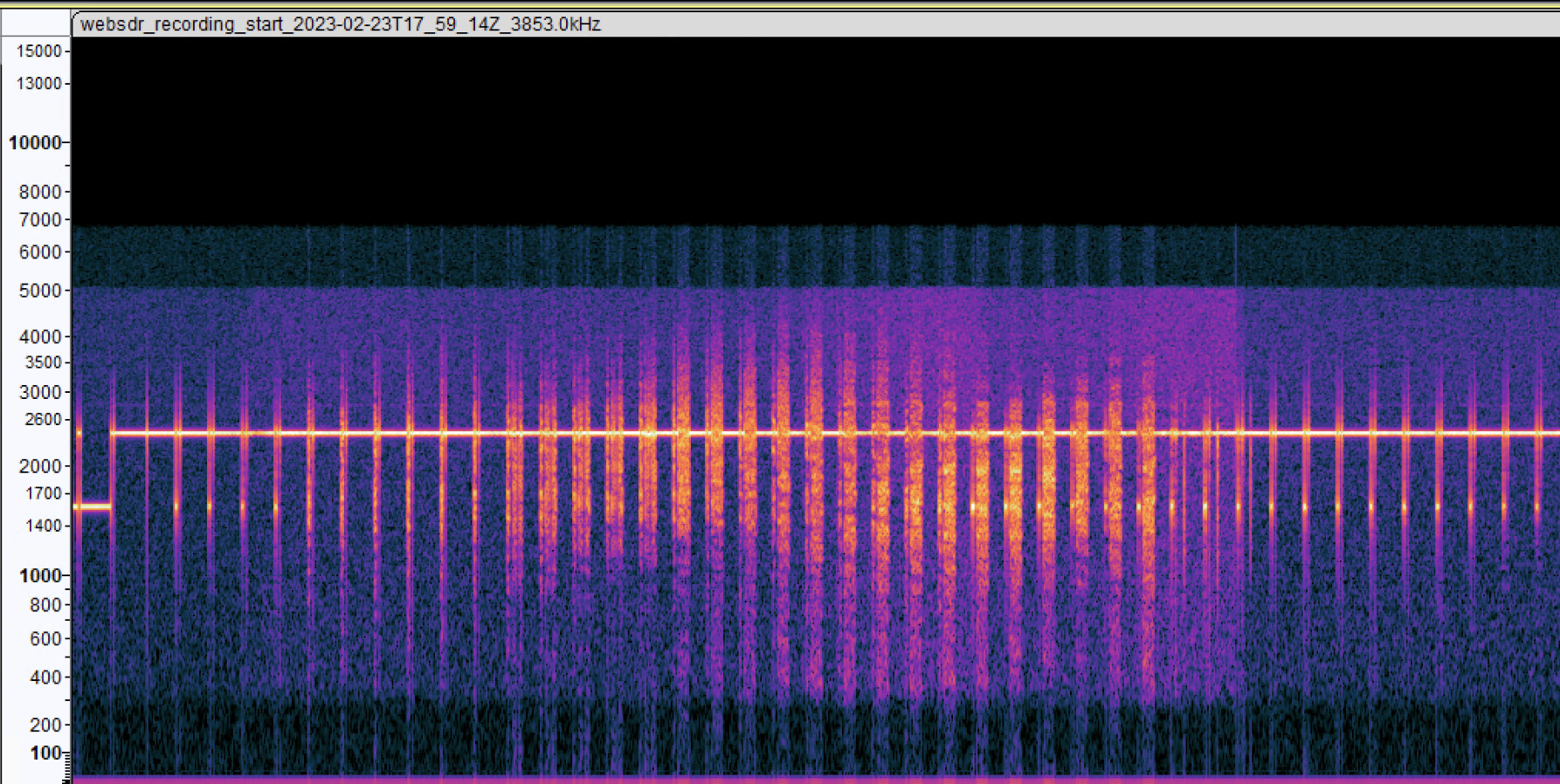
Below is a segment of such a recording, showing the spectral content vs. time. The relatively high bandwidth is shown, and this bandwidth is proportional to the frequency content of the signal. This case shows mostly empty lines, with text near the middle of the recording.
Future Work
I will likely remove the internal AM demodulator, and replace it with a new custom board containing an ADAU1701 demodulator.
One neat idea is to use e.g. an ESP-32 to drive the printer with synthetic images directly, allowing it to act as an image-printer. This would require additional effort, but in principle all that's needed is to generate start & phasing tones, then scan out a bitmap at a suitable rate.
As noted above, the phasing circuitry is complex, and there are indications that it remains active for longer than the current duration of sync pulses. If this is true, then a modification will be attempted to reduce the phasing time to less than 30 seconds. Failing this, I may have to find some way to increase the phasing circuitries loop gain.
I may also look further into the dynamic stylus correction feature to determine if this is intended to correct horizontal head offsets, since I didn't initially try this method.
The two previous have been implemented in part 2!
Adding a bar-graph circuit to show the video levels would be fairly neat, the bar graph can be fairly trivially retrofitted to show video levels in real-time.
I am also considering adding some type of phasing-aid circuit. My thinking is that adding a bi-color LED and driving one from the internal phase-reference pulse, and the other connected to the video signal (active when white) could be sufficient.