Upgrading Icom H16T ROMs to Super 150 V200T Firmware
In this article I desribe how you can upgrade your H16T to use the Super-150 custom firmware developed for Icom V200T LMR radios. Be warned that some hardware modding and EPROM programming is required.
Why?
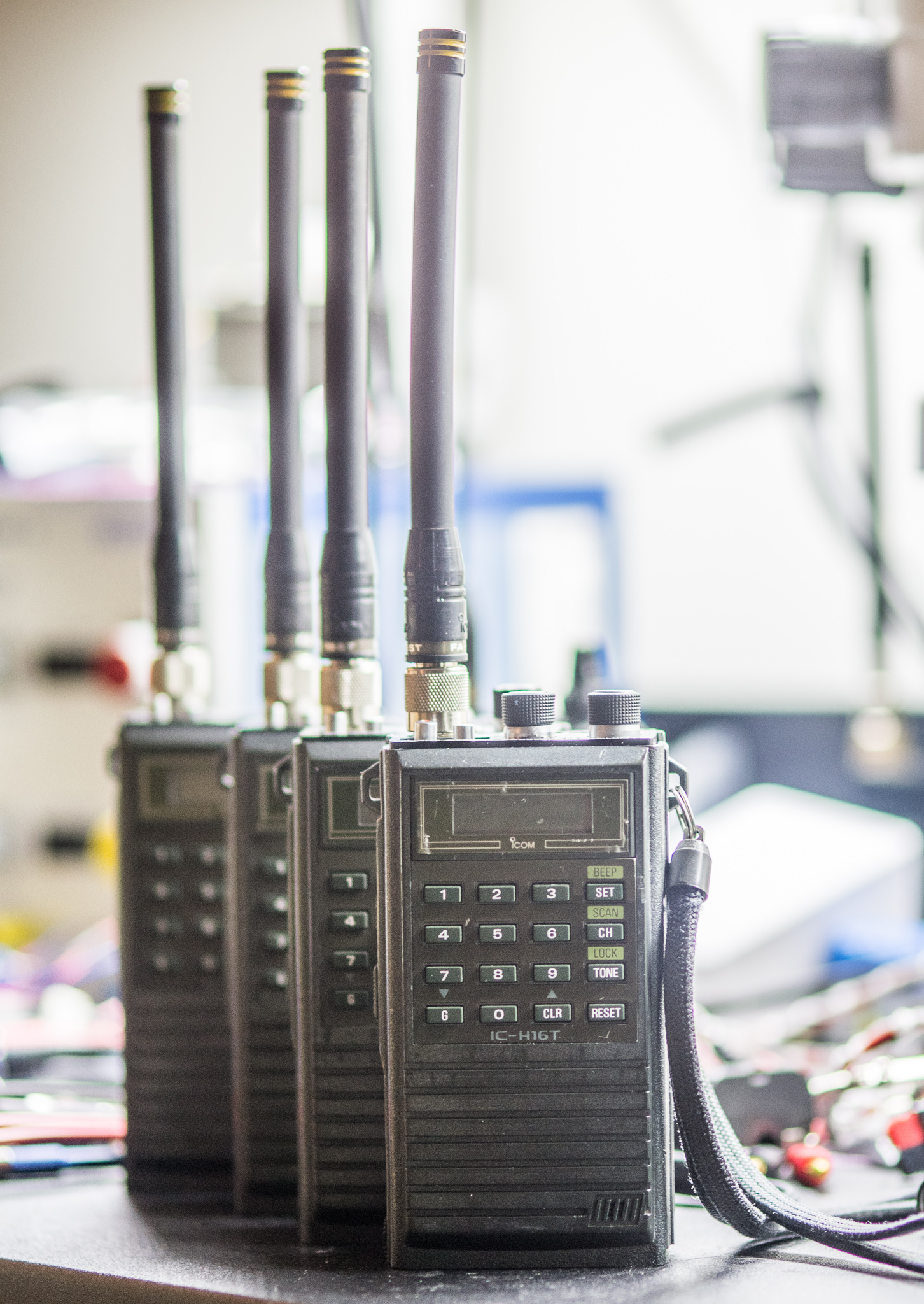
The H16T is a pretty nice radio, it's big and if not entirely built like a brick then it's certainly shaped and weighted like one if you use the old batteries.
However the software is tuned to 5-tone signalling normally, there's no support for showing the frequency on the display and keypad programming is a little tedious. The fairly large display will only display the channel number and 5-tone dialling code, not very useful these days.
The biggest issue by far with these units is that the software that came with most variants in Norway (version 1 or 2) is unable to self-initialize the RAM, requiring cloning from a functioning unit or using some highly obscure DOS software I wasn't able to track down.
This means that when the RAM batteries start to die your H16Ts turn into literal bricks unless you keep up with replacing batteries and cloning them.
I have recorded the clone sequence in case I need it, email me if you want to make an arduino sketch to spit out the clone sequence or something.
The Super 150 software is tuned towards relatively easy front panel programming, supports most normal ham radio features and is generally just nicer to use. It also self-intializes the RAM if it's blank.
This means that with the S150 image installed you don't have to worry about that battery again.
Needed Parts
I'll assume that anyone reading this can figure out taking the radio apart, but obviously you need tools for that.
You'll need access to the following:
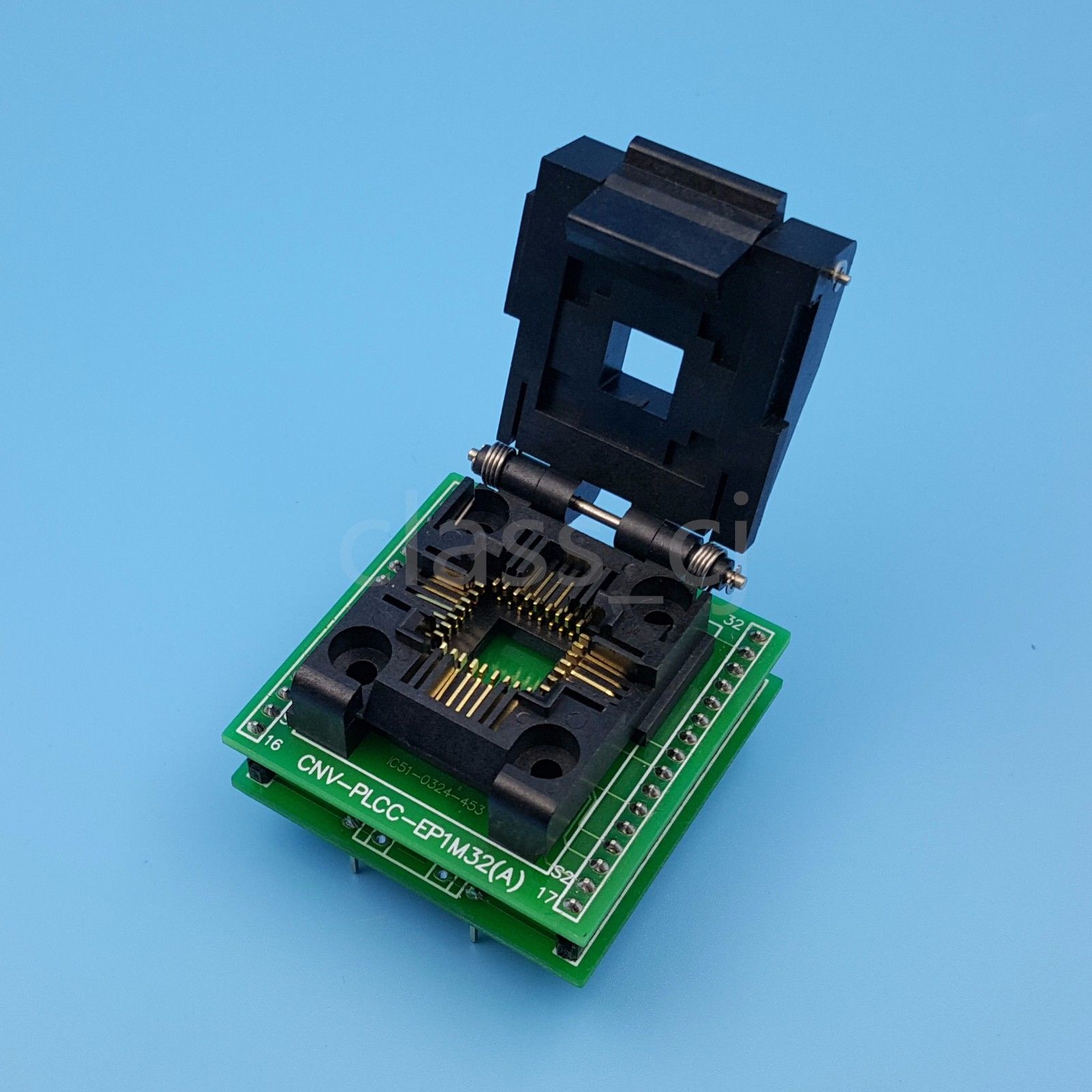
- CLCC32 adapter if you have a H16T mk.II (see below)
- PLCC removal tool
- EPROM programming tool, the TL866CS (MiniPRO) is cheap and works well
- EEPROM eraser or a lot of high altitude sun and patience
- Maybe some labels for the ROM
- Possibly a new battery, tabbed CR-2032s work here
Know Your H16T
I tried this approach on two HW revisions of the H16T, most of mine had a newer type of logic board which seems to be identical to the one used in the H16TmkII instead of any of the variants described in the H16T manual.
The easy way to tell these apart is to look at the model number under the keypad. If it simply says IC-H16T with center justified text then it's a MkII. The older variants had the model right justified. However, I did find a couple that had the MkI face place with MkII internals, so don't take it for granted.
The MkII variants I had used the Logic board from the MkII but still had the MkI outer casing.
I haven't attempted to do this mod on the Mk.I units since I only had one and needed a parts unit to get the others running.
Programming
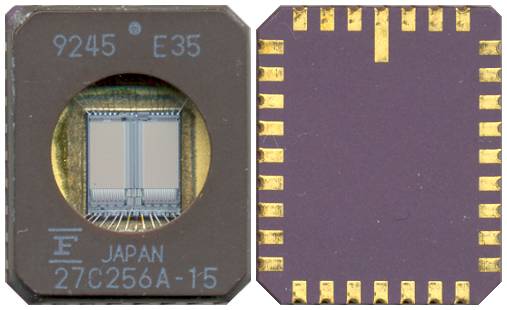
The MkII boards use a 27C256 EPROM in a deceptive package; to the untrained eye it looks like a PLCC32 device but when you pull it from the socket it becomes clear that it's a CLCC32 package.
This is a smaller - somewhat obscure - device and the socket is lower profile than PLCC32.
Your standard PLCC32-DIP32 eBay adapter using a standard socket will not fit as it connects on the sides of the pins; modding is not an option if you want any kind of reliability.
Fortunately the "clamshell" type adapter that uses a ZIF socket will work since these connect on the bottom of the device where most of the metallization is on the CLCC. I recommend getting this kind of adapter anyway since the eBay special standard socket adapters have given me trouble with dodgy contacts before.
You'll may want to get a PLCC extractor tool, though these CLCCs are fairly easy to get out with a small screwdriver or pick if needed.
As always I recommend reading out the contents of the ROMs before erasing them; fortunately Icom did use windowed packages (the CLCC32 is a pretty rare EEPROM so don't lose them either).
H16T Mk.I modding
The Mk.I variant with DIP ROMs will need some mods to actually work right with a larger ROM.
Originally the ROM designed into the H16T was a 27C64, this was later changed to a 27C256. To support this you need to add two mod wires, and hack in a transistor inverter as shown below (copied from original dealer documentation):
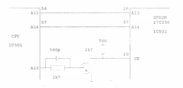
These mods are also done on the V200T to run the Super 150 software if you have an older model.
Note that most V200T modders skip adding the transistor and only apply the two address lines mods, not sure what will stop working if you skip the transistor mod.
Note: I haven't actually tried this mod on the H16T Mk. I yet. It looks pretty tedious.
PLL Issues
The CPU, memory, IC layout etc. is basically identical between the V200T and the H16T. There is one significant difference: the reference frequency is different.
This will cause an unlock with the new firmware, and the speaker icon in the display will flash slowly to indicate an unlock error.
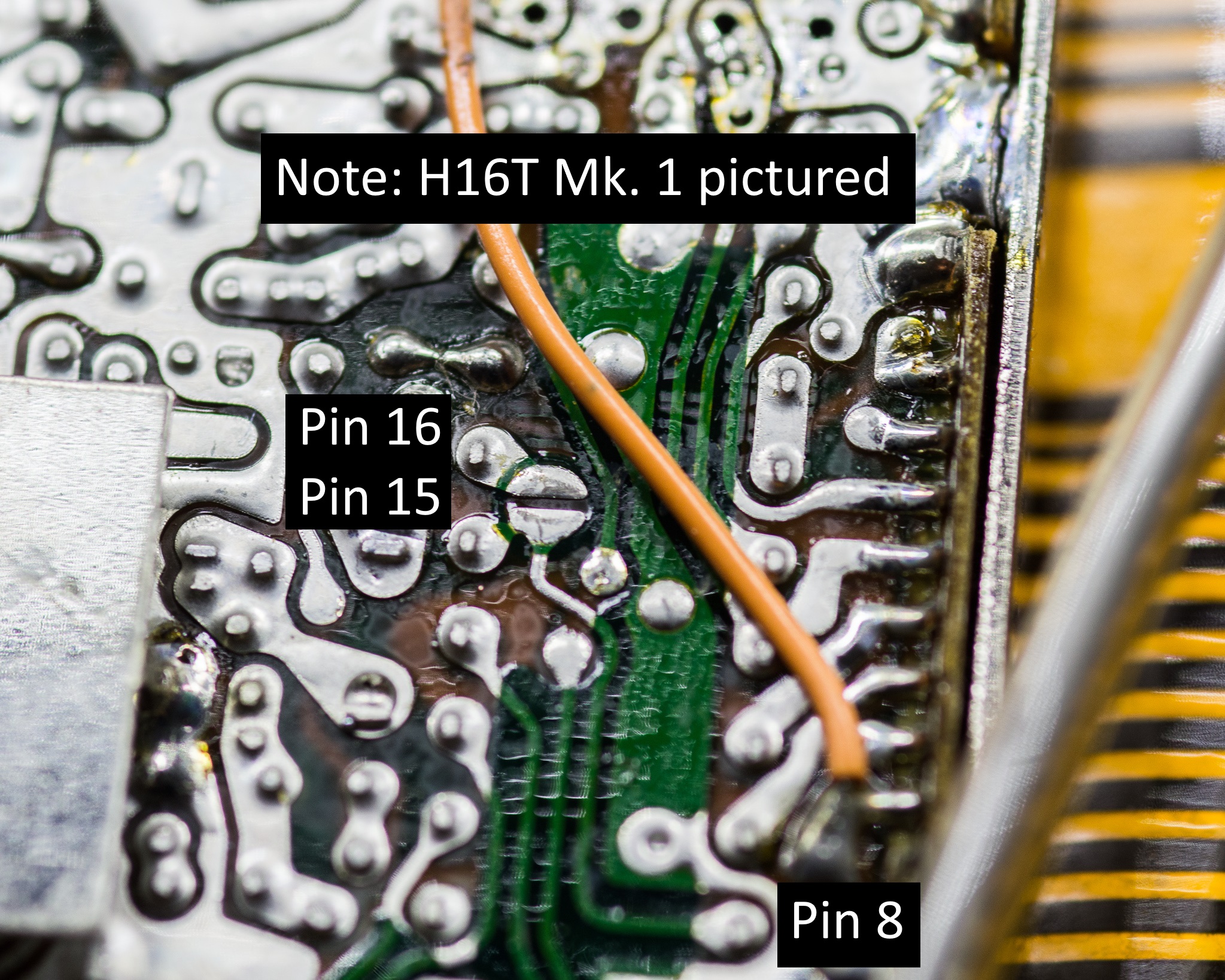
The reference frequency is selected by using one of three outputs from the PLL IC and connecting that to the R input (pin 8).
The V200T firmware expects a 6.25 kHz reference while most H16Ts use a 12.5 kHz reference. On the bottom of the PLL PCB the are some classic solder-circles that let you easily change this connection, pin 8 of IC202 by default connects to pin 16. Just remove the solder bridge and make a new one to pin 15 to correct this.
This also makes it pretty easy to reverse this mod.
Burning the ROM
Now you have the required hardware, the PLL is modified, the ROM erased, and you're ready to burn.
Normally you'd program the V200T firmware but there's another difference: the CTCSS encoder is different. The V200T firmware has a LUT to convert the CTCSS number you input to a 6 bit code, while the H16T just shoves the number directly into the encoder.
Modify the firmware as such:
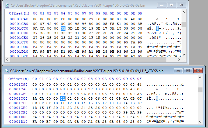
This was very easy to work out since Icom gives the V200T frequency vs. digital code table in the service manual. These are changed to a linear count to give correct CTCSS frequencies in the H16T.
The modified firmware can be downloaded here: super150-5-0-28-03-09_H16_CTCSS.bin
At this point the new firmware can be flashed and installed, you might need to disconnect the battery temporarily to clear the RAM after.
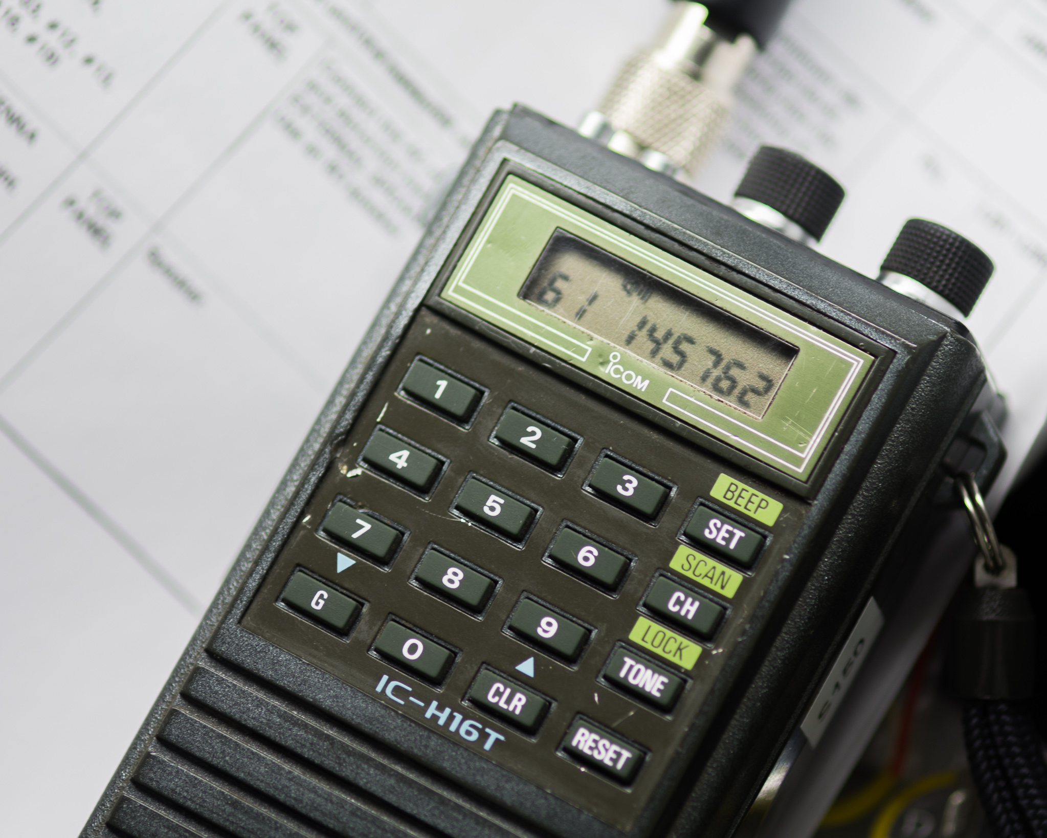
When powering on it should read "CLEAR" the first time, then "SUPER 150".
In Use
You can program channels using documentation for the V200T, like this: https://www.pa2jfx.nl/?pid=Z2U%3D
Note that unlike the V200T all H16Ts have CTCSS encoders, the codes listed in the V200T documentation works for this. There's no CTCSS decoder in the H16T unfortunately.
There's no keypad lock in this software since the V200T doesn't have a Func key, this basically works like the on-hook detector would in the V200T. This is a little annoying and may be an issue for portable use.
The upside is that you get 80 channels with this firmware, a pretty impressive amount for a radio from the late 80s.
Troubleshooting the H16T
Here are some issues I encountered when working on this that may help you:
- Blinking speaker icon
Caused by PLL unlocks, check the PLL R/V ports and lock detect. Correct lock frequency is 6.25 kHz for newer V200T based variants and 12.5 kHz for older types.
- Radio forgets memories when left off for a while
Check the battery voltage, 3V or higher is usually fine.
Alternately: this can be caused by an intermittent fault in the flex circuits between the boards, I had to reflow the Logic board flex to fix this issue on one of the units.
- No output power, no errors, receive fine
Bad PA, most likely. Check the PLL during TX (or use a spectrum analyzer sniffer to check if the VCO is at the TX frequency).
- No CTCSS
In one of my radios the 3.57 MHz crystal for the CTCSS generator IC was broken and the CTCSS output was sitting at 1/10 of the normal frequency.
I replaced the crystal and this problem was resolved.