DigiDesign Pro Tools Audio Card

The Pro Logic Audio Card, sometimes known as the 442 Audio Card, is the default computer interface card to drive the previously discussed Pro Tools Audio Interface unit.
Table of Contents
Overview
The 442 Audio Card (also known as the SA4) is a key part of the Pro Tools experience:
Specifications for 442 Audio Card.
The 442 Audio Card (MH030, SA4, Pro Tools Audio Card) is the NuBus card used in the original Pro Tools system. It supports the 442 I/O or ProMaster 20 Interface.
Output: 4 channels of phase synchronous 16 bit audio.
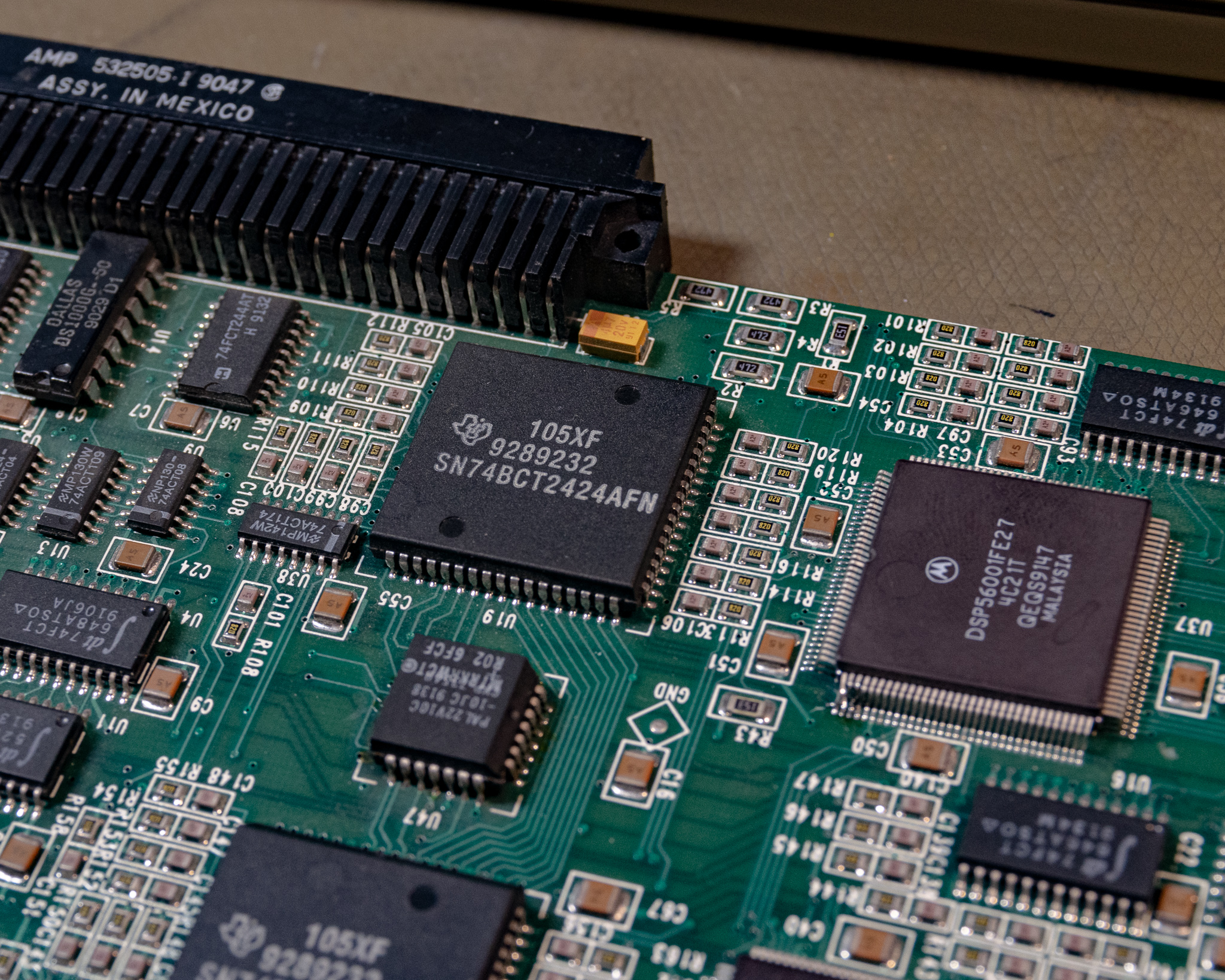
DSP: 2 Motorola 56001 processors.
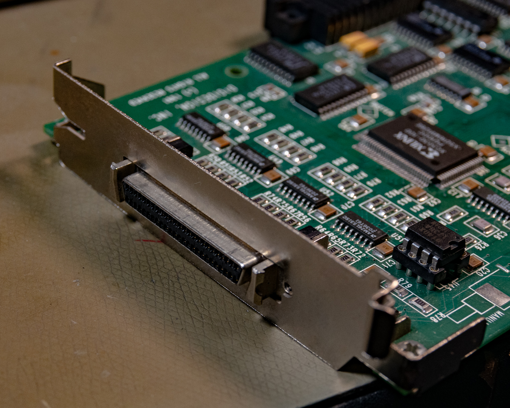
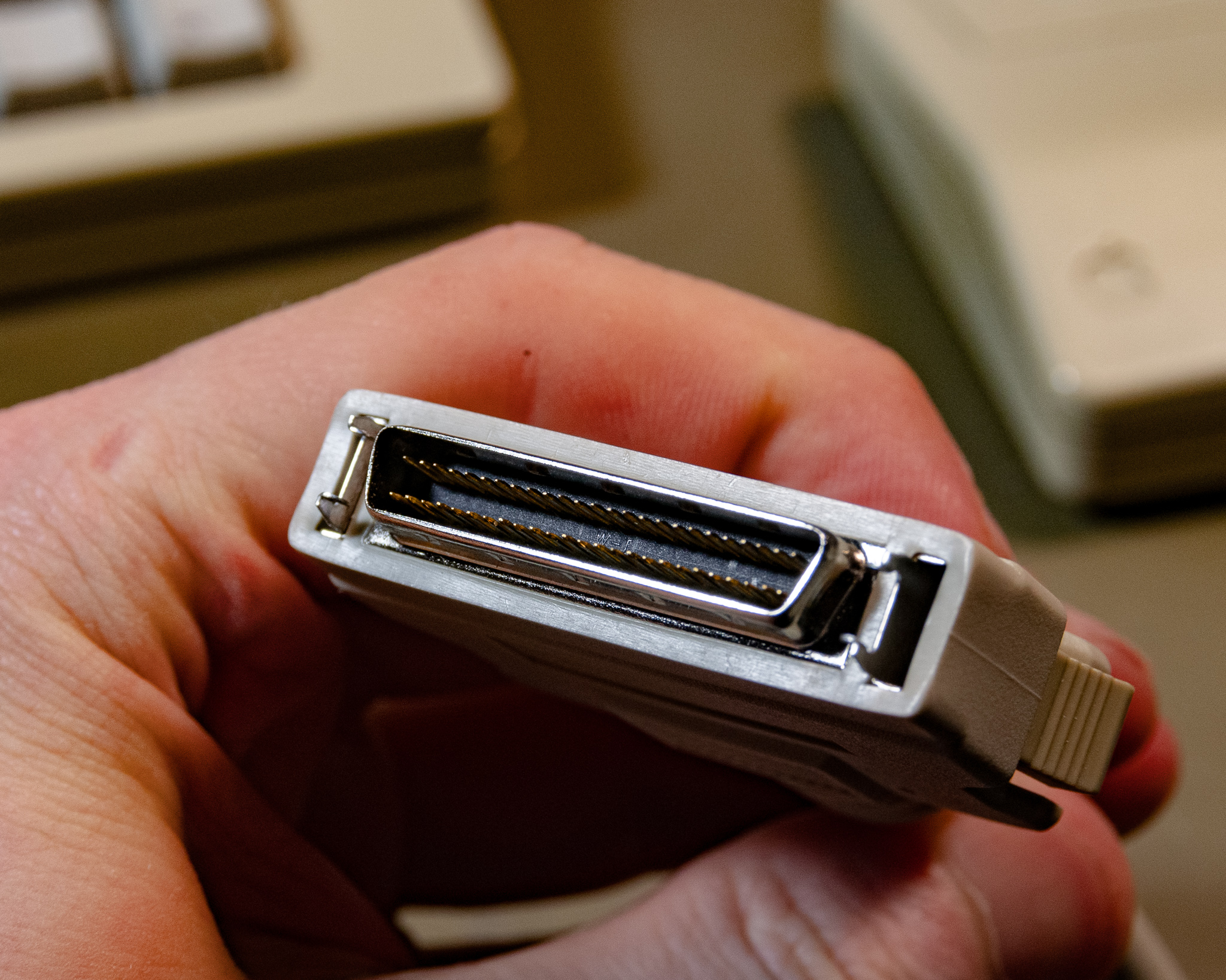
Connector: SCSI2 (50 pin).
NuBus power consumption: 9.55 watts.
DSP Clock Speed: 32mHz
Current Xilinx chip (U45): rev R03
ID:53 Created:12/03/1993
Amazingly, the card is able to process 4 audio channels in real time while running at only 32 mHz or 0.032 Hz! Now that's efficient programming!
It is worth noting that the standard configuration only allows for 1-channel recording, but it will do 4-channel playback and seems capable of 4-channel monitoring with 1 recording.
The card does not appear to be supported by anything newer than Pro Tools 3.2 — the free 3.4 version will not work. It is officially supported on the Mac IIfx, though on that computer you have to set the serial ports to "Compatible" mode using the Serial Switcher application. Otherwise, it crashes on startup.
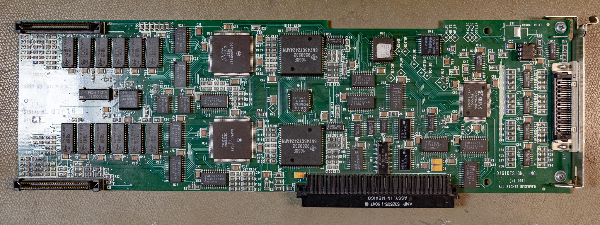
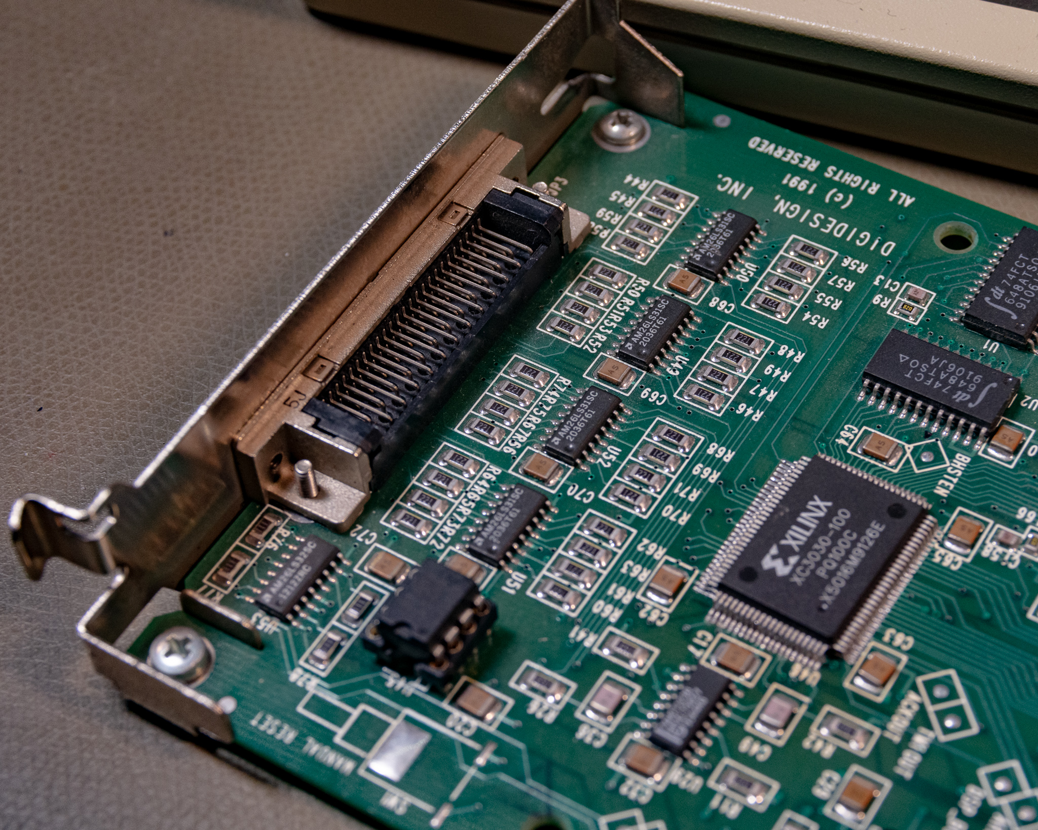
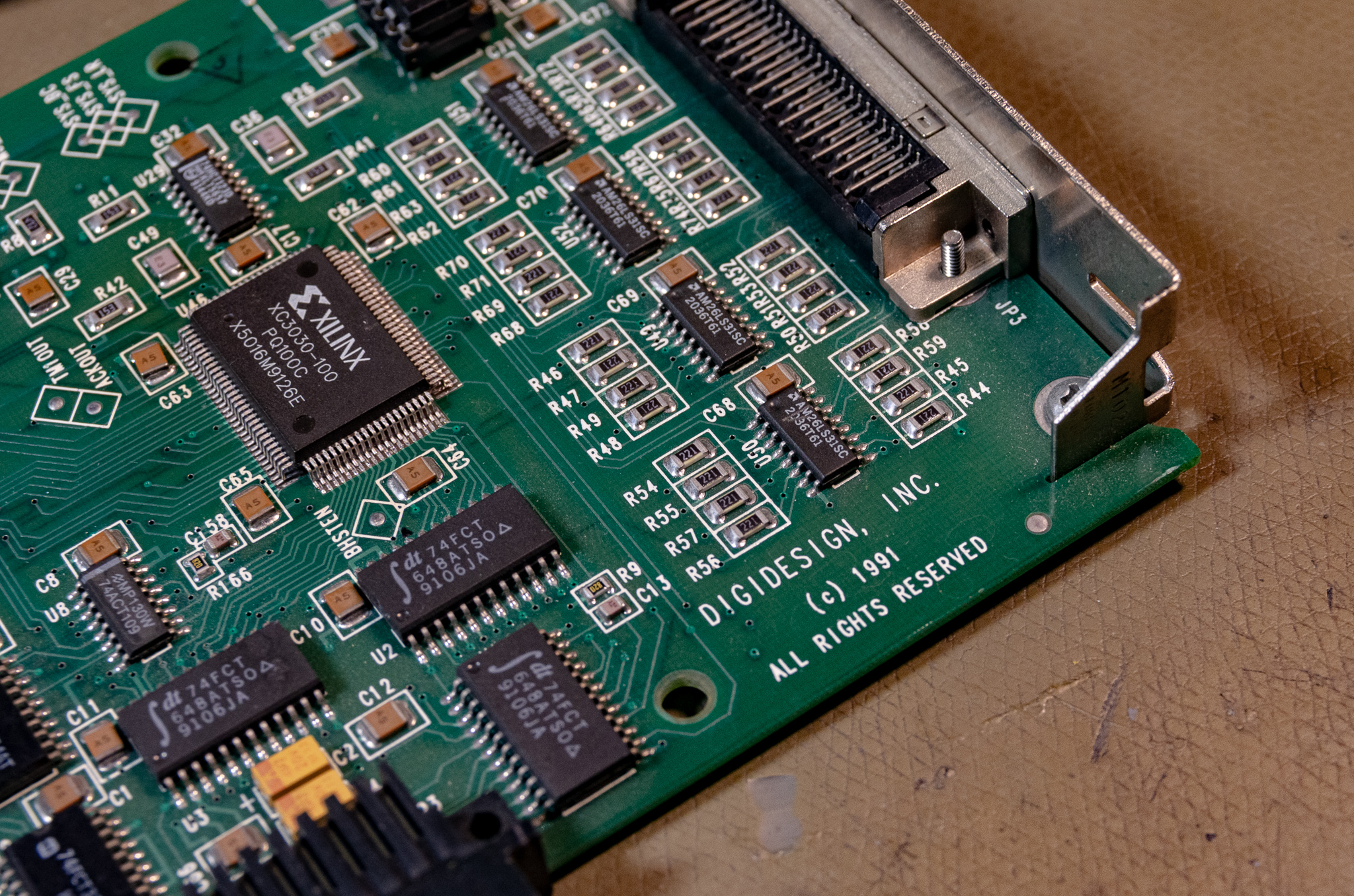
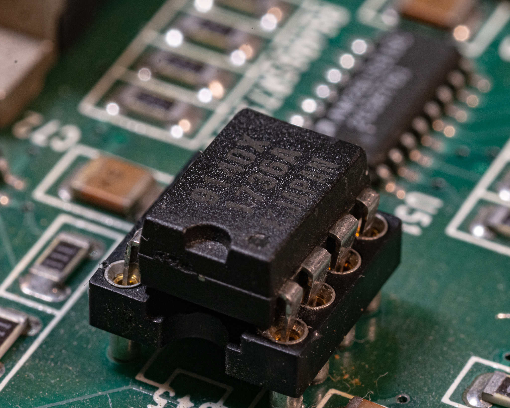
The card is highly advanced, surprisingly it contains one of the first FPGAs ever commercially manufactured, the Xilinx XC3030-100. Note that I photographed the card after desoldering the FPGA, so it's just sitting in roughly the right spot.
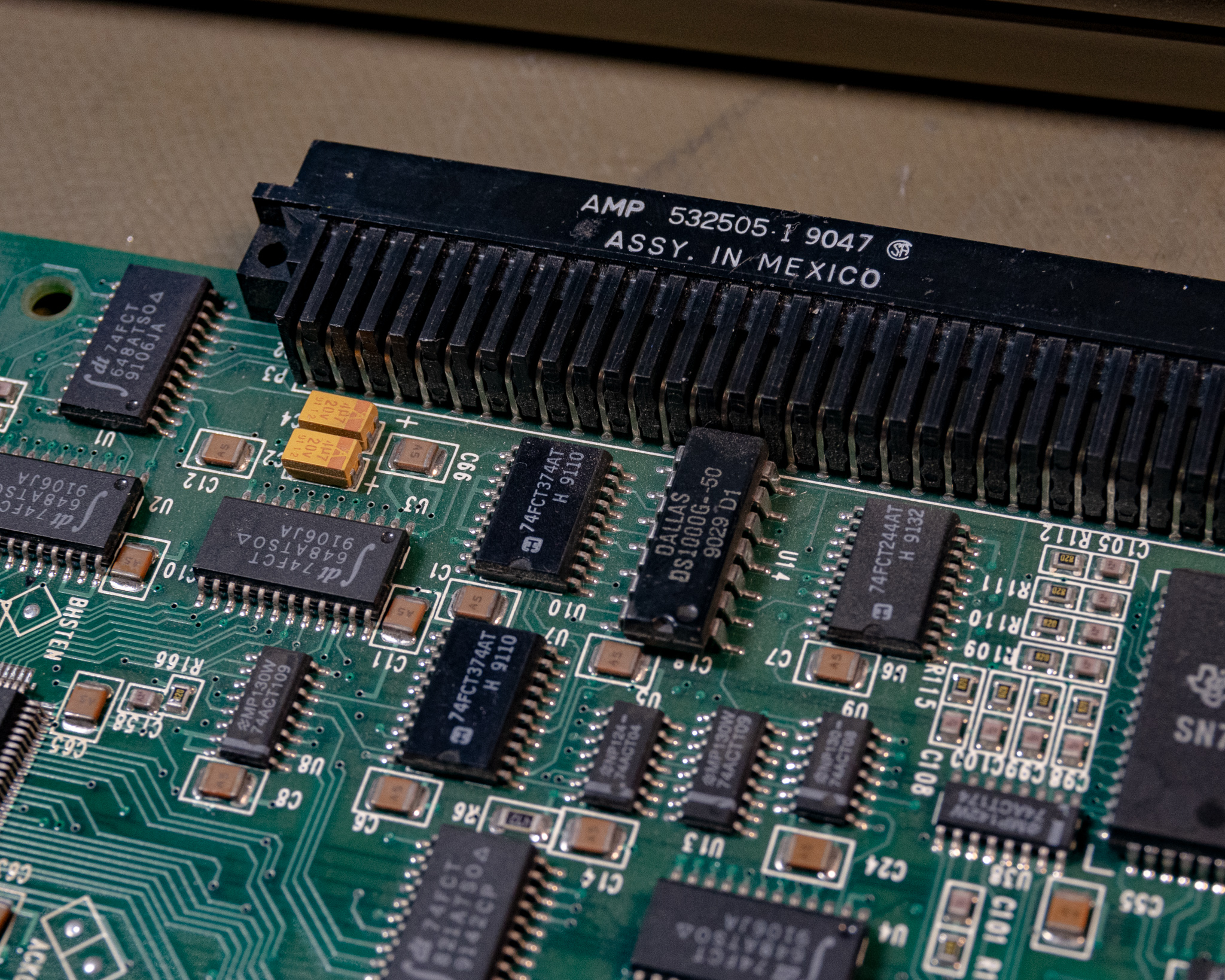
The over all build quality and technology is excellent, definitely higher end than the 442 Audio Interface it drives. The card includes several fairly fine pitch QFP packages, and is all SMD except for the connectors and SPROM socket.
Looking around eBay it looks like another board revision used plastic DSP chips and an AT&T FPGA chip. There is also a similar board using only 1 DSP on the market, but not too sure exactly what that card is compatible with.
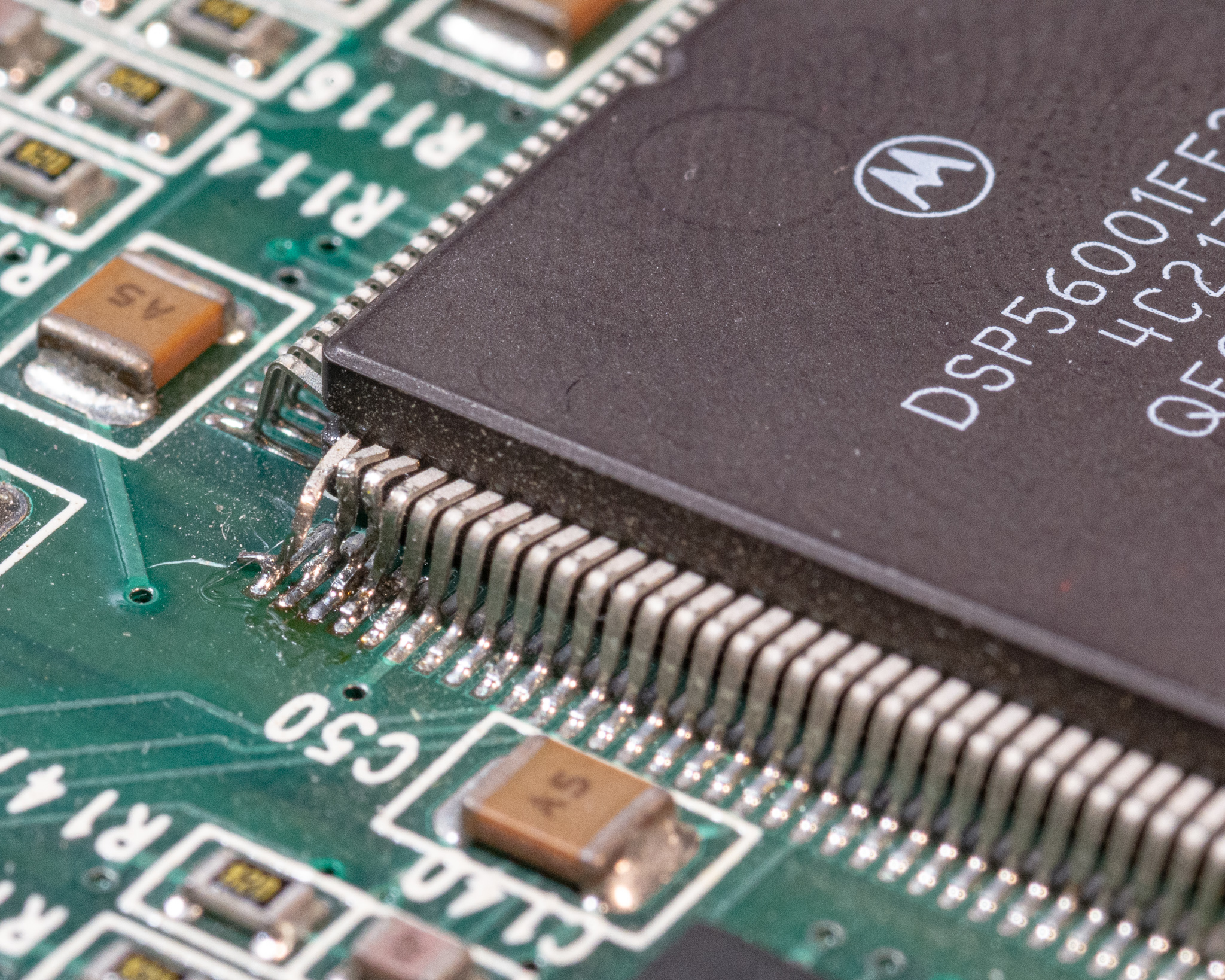
DSP-56001
The big beefy brains of the card is a dual set of Motorola DSP56001 DSPs running at a blazing 32 MHz according to the documentation. However, the IC markings indicate they are 27 MHz variants. It could be they are overclocked, or they might actually be running at 16 MHz or similar.
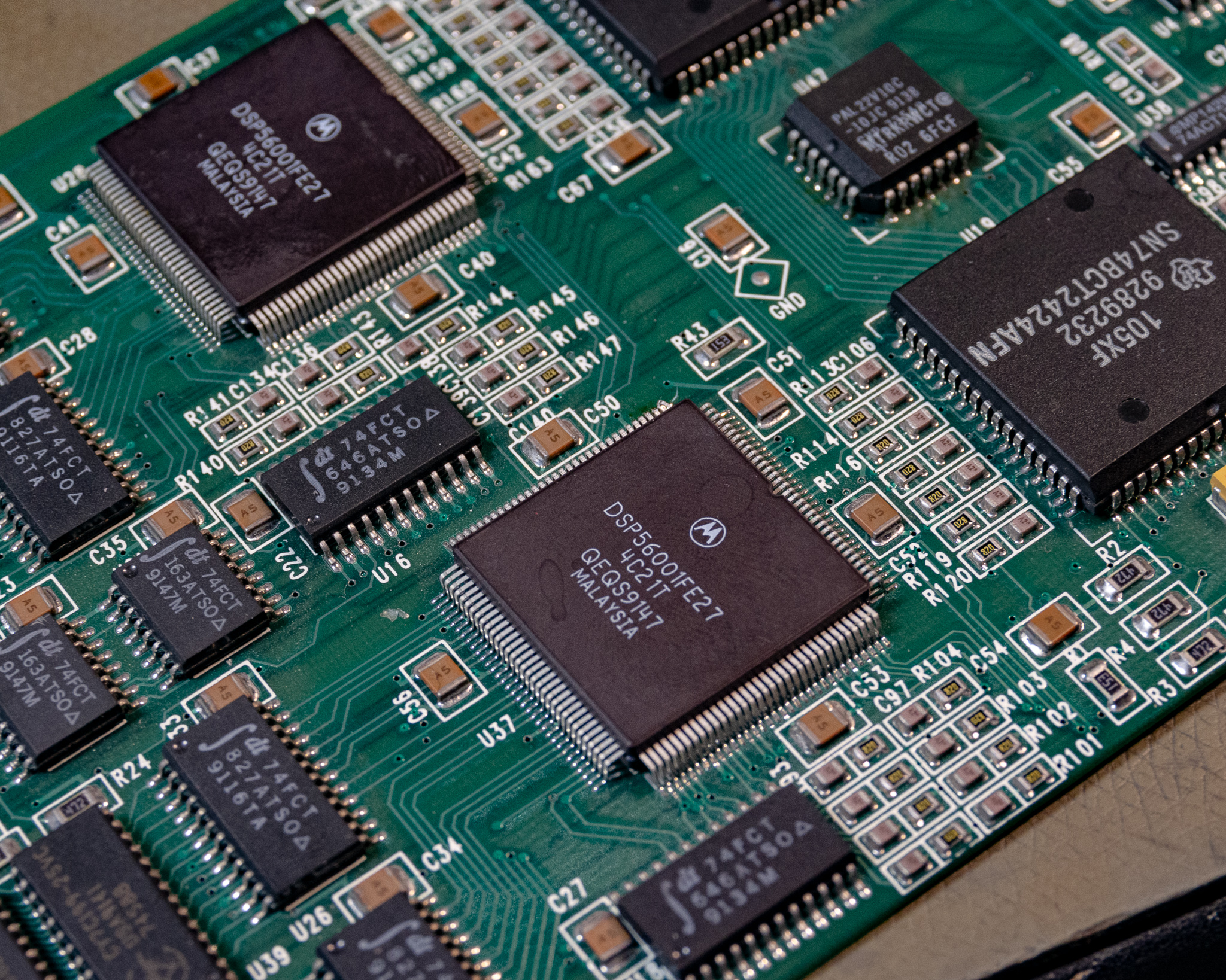
These DSPs are almost certainly running highly optimized routines designed to process the data as required for the Pro Tools software. They are packaged in a pleasing ceramic QFP package. It looks this this exact combination is fairly rare, and a PGA type package was probably more common.
As far as I can tell the DSP56001 has a common bootstrap ROM and program RAM which is presumably loaded from the computer, so replacing a broken one could be possible.
This paper describes the architecture and applications of the DSP56001, a RAM-based member of the Motorola DSP56000 family of high performance, user-programmable CMOS digital signal processors. The DSP56001 has 512 × 24 bits of program RAM and special on-chip bootstrap hardware to download user programs from an external memory or host processor - https://ieeexplore.ieee.org/document/1169716
The plastic packaged QFP is probably compatible, and is far easier to find than the ceramic variant.
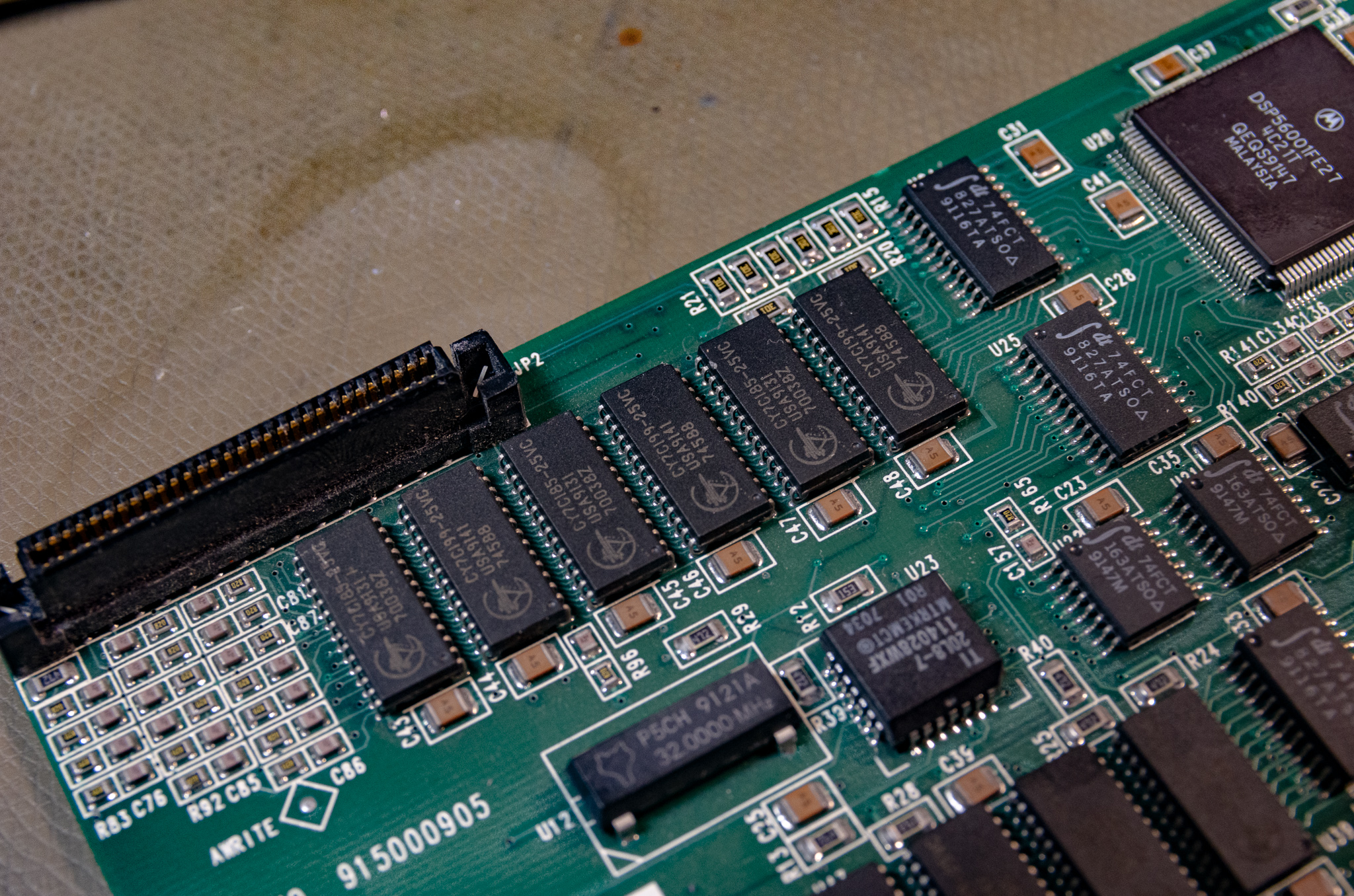
Each DSP has 6 pcs CY7C199-25 32k⨉8 SRAM chips, providing a suitable fast local storage RAM. Each RAM set also has a high density connector which was probably used to add even more SRAM.
External I/O
The card has the same SCSI2 connector as the audio interface, and uses standard AM26LS31/32 ICs.
Other
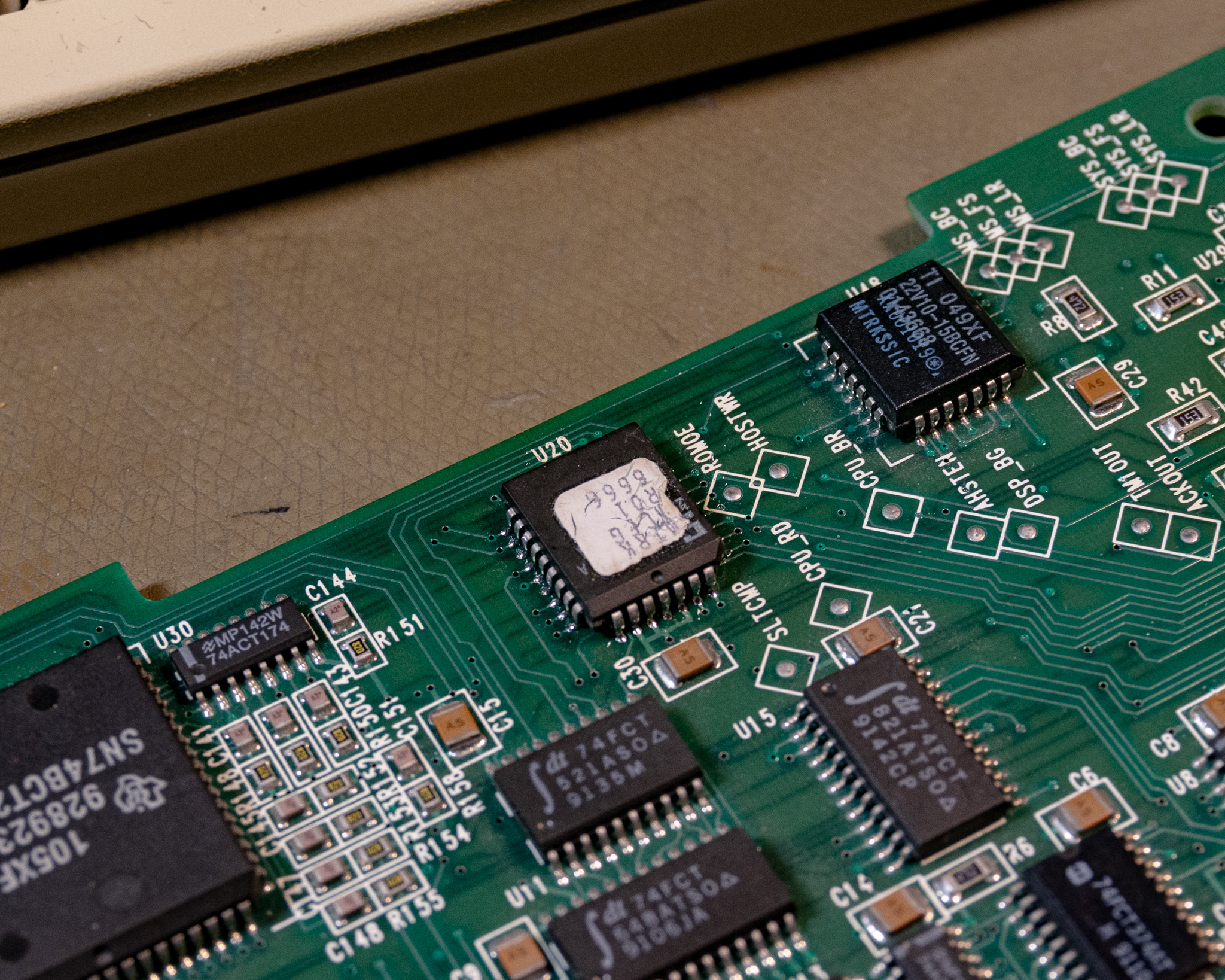
There a few PAL22V10 PALs for various interfaces around the board. Not sure how/if one could dump those for archival purposes.
The NuBus interface appears to use two SN74BCT2424AFN 16 bit latched bus transceivers, a very obsolete IC designed specifically for NuBus applications. There is also a selection of 74F(CT)244, 374, and 648's to handle various latching and decoding functions, including RAM interfacing.
The bus interfacing appears to be a mix of 74F logic and the NuBus ICs, there is also a DS1000 delay line (SMD-DIP package) for some reason. Presumably to resolve some timing issue. I've noticed a similar function on other NuBus cards, so it's probably some quirk/bug in the NuBus implementation or spec that this solves.
Pro Tools
I don't have a huge amount to say about Pro Tools, but I took a screenshot of the software in use.
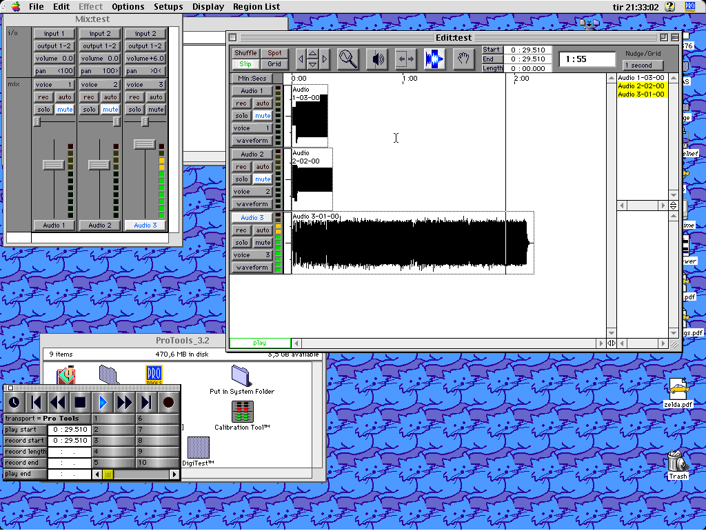
Above I had recorded some audio into several tracks, and was playing back the last recording (Audio 3).
I also used this setup as an audio player for a while, this was an enormously tedious process. To convert PC sourced PCM .wav files to Pro Tools format you can convert them to an appropriate Mac PCM format using "SoundApp 68K", and import the files into Pro Tools.
The novelty was there, and I even converted a 5.1 mix of Dark Side Of The Moon into a quadrophonic mix and was able to play it back in real time using the 4-channel output.
Playback works best from a fast local SCSI drive, but I was also able to work off an AppleTalk server running Windows 2000 Services For Macintosh (using Token Ring, even).
Troubleshooting
My card was very cheap, since it had some broken connections (probably dropped or stored improperly). A few of the pins on one of the DSP chips were squished together, and a few of them had broken off from the PCB.
This was a simple fix with decent soldering tools and a microscope, the pins were pretty flexible so no lasting damage.
FPGA
On power-up, the card was dead, no detection at all, just like the old miro card. After doing some scientific troubleshooting (touching ICs to see what was warm), I found the XC3030 FPGA was extremely hot. Definitely far hotter than it should be, I could smell how hot it was.
I initially didn't expect that chip to be an FPGA, assuming it to be a CPLD due to how rare FPGAs were in 1991. If that were the case then rescuing the board would have been impossible without at least a working reference to try to dump the CPLD configuration from.
However, after checking datasheets I found it was an FPGA, and it used a "standard" XC1700 series SPROM (Serial Programmable ROM). This chip was sitting in a socket in a corner, and it's the key here, since the FPGA loads its configuration from that chip.
With a working ROM chip, the FPGA can simply be replaced and the new one will load its configuration automatically on startup.
I ordered a replacement FPGA, I found that the XC3030A is bitstream compatible according to Xilinx, and the XC3030A-7PQ100
All of these new families are upward-compatible extensions of the original XC3000 FPGA architecture. Any bitstream used to configure an XC3000 device will configure the corresponding XC3000A, XC3000L, XC3100A, or XC3100L device exactly the same way - Xilinx XC3000 Series Datasheet
Xilinx PDN2003-03 lists the XC3030A-7PQ100C as the recommended replacement for the exact part that was there originally. The C/I suffix indicates commercial vs. industrial temperature specifications. The -6PQ100C is a slightly faster chip which will probably also work.
FPGA Configuration ROM
I decided to archive the configuration in case some damage occurred to the SPROM. Unfortunately I had to improvise a bit, and ended up using a breadboard with a 10 kHz external clock to clock out all the data. I used a logic analyzer to record the applied clock and the data output, then I wrote some Python to interpret the logic analyzer decoded bitstream and do some basic checks for integrity.
The total SPROM size is 36288 bits long, and it appears that the SPROM stopped doing anything at all after that number of clock cycles. The actual FPGA configuration size is 22176 bits (22216 with a 40 byte header in the PROM)
If you have a dead configuration PROM, this might help you if you can get hold of a suitable programmer. The Xilinx HW-130 is one option (it can't read/write the XC1700A, but can do the D and E series). You'd probably need to re-format the bitstream to a supported format like Intel Hex before it would accept it. May also require some padding if the size of your SPROM is different, like if you use a XC17128.
Modern SPROMs are still used, and may be compatible with the interface of this ancient one. Modern ROMs are typically programmed over JTAG, so that part should be fairly well documented.
EPROM
There is a 27C64 in PLCC-32 package on the board, connected to the FPGA. I desoldered this chip and dumped it for archival purposes.
The chip is mostly blank, near the end there is what looks like a typical NuBus declaration. Most likely this chip is only used to ensure the board is detected by the computer, and all other DSP code etc. is loaded by the system extension provided with Pro Logic.
Here is the ROM if anyone ever needs it: 442_BUS_ROM.zip
ROM/SPROM dumps
The set of FPGA configuration and EPROM dumps + some notes is here: 442_DSP.zip
The EPROM dump is very simple, you can use any 27C64 PLCC-32 with a TL866 programmer to write it out. The chips on the market now are OTP devices (no window), so maybe buy a few. I used a ZIF socket to read out the old one, as I've had bad luck with standard sockets. The contents contain text, and the checksum matches what was written on the label, so it should be an accurate dump.
The FPGA dump contains both what I believe is an accurate dump, as well at the relevant DSLogic logic analyzer traces in case you need to re-analyze it. I also included a Python 2 script to convert the .csv file from the bus decoder in the logic analyzer to a straight binary file. The sectioning of the CSV data (from 1st valid clock cycle to end of contents) was done manually.
The archive also contains the XC1700E and XC3000 series datasheets for reference.