ITT Mackay Marine 3021N Details (Part 2)
This is part two of a series covering my extensively modified ITT Mackay Marine 3021N communications receiver.
This article covers various details on the chassis and the signal path. More details of the various cards are given in later articles covering their replacements. The work covered in this section took place between 2017 and 2021.
Table of Contents
Signal Path (Stock)
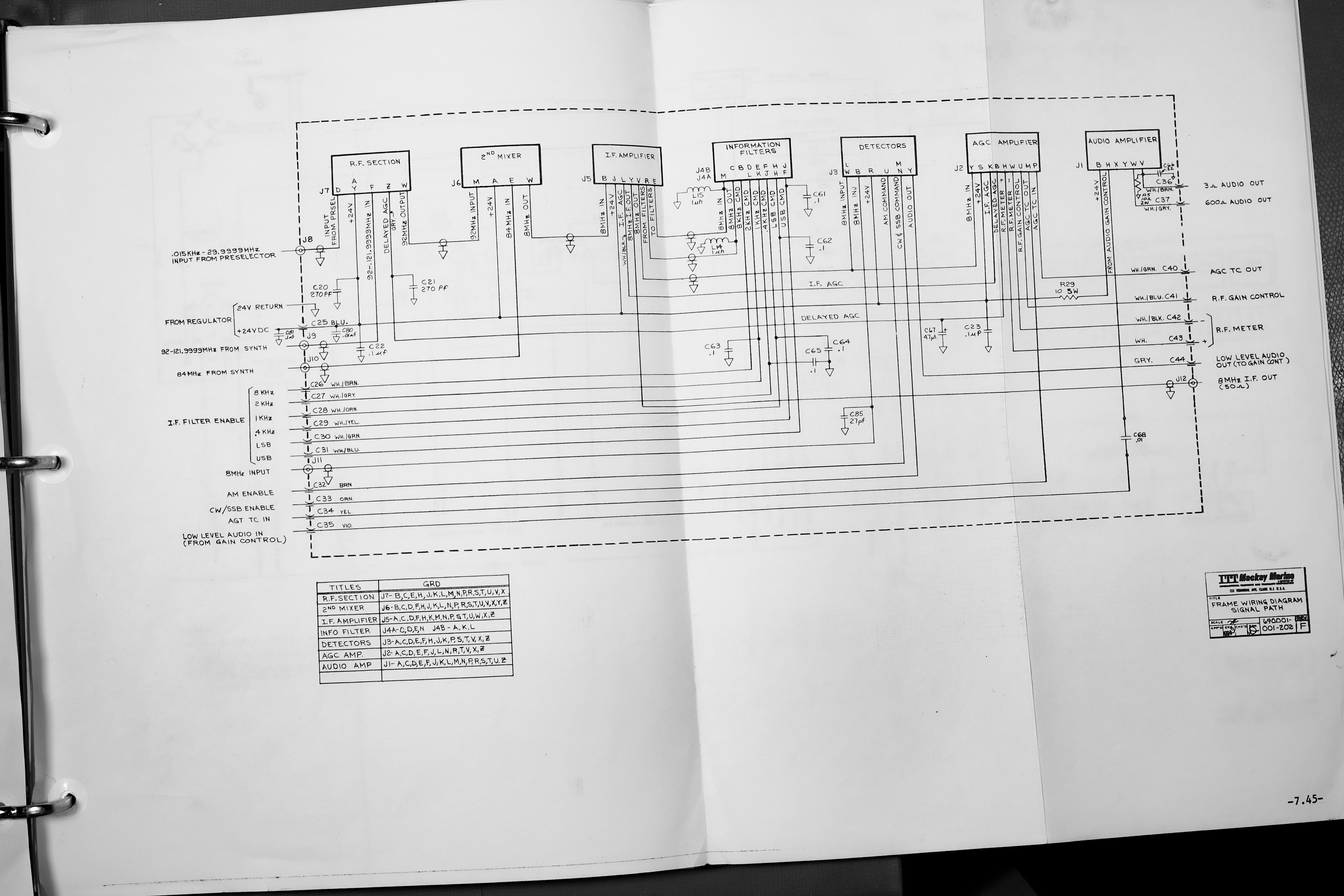
The 3021N is a double conversion superheterodyne receiver with a 92 MHz 1st IF and an 8 MHz 2nd IF. The RF signal is routed through the preselector, amplified, and mixed up to 92 MHz. Two 92 MHz crystal filters set the maximum IF bandwidth.

The 2nd IF of 8 MHz has one fixed 6 kHz wide filter, and is followed by the filter selector which can select between bypass (pad), 2 kHz, 1 kHz, 0.4 kHz, or SSB filters.
The signal is detected at 8 MHz using either an envelope detector for AM, or a product detector for all other modes.
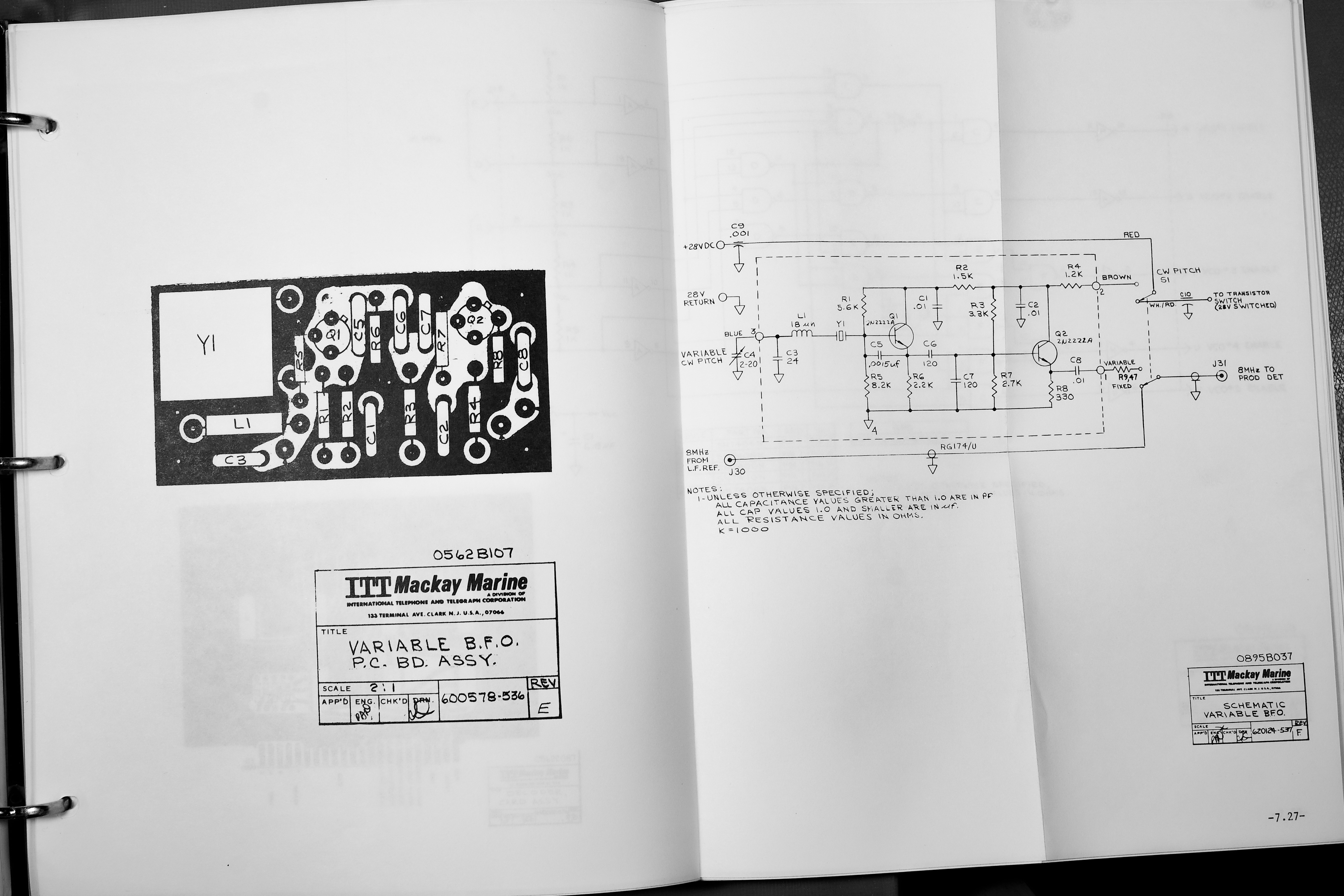
The product detection is slightly peculiar since the reference frequency is either the radios reference oscillator (controls the synth as well), or a variable crystal oscillator, and the type and tuning is selected on the front panel. This means that the only difference between SSB and CW modes is that CW modes uses the normal information filters. You can swap in the variable beat tone in both CW and SSB modes to frequency shift the recovered audio.
The AGC amplifier system also operates off the 2nd IF.
Repairs & Issues
I've noted some of the issues I had with the receiver, which is part of the rationale for replacing all the internals.
IF Filters Repair
When I received the radio, the 1 kHz IF filter was defective. Upon inspection I found that one of the crystals had a DC short. I was able to unsolder the filter can, and found what might have been a tin whisker shorting the ceramic feed-through to the case inside the crystal. Upon removing this I was able to reassemble the filter and the 1 kHz filter did work.
IF Filter Issues
The IF filters are not that great, there is no adjustment on these, but they were either mediocre from the factory or they have drifted over the last 50 years. Each filter has its own issue, the narrower filters are extremely lossy for example. According to the documentation all filters should have 6 dB loss, but the 400 Hz filter was closer to 30 dB.
The LSB filter is quite poor, the pass-band is slightly offset, but it also has a significant drop at the lower end, which results in poor treble in the LSB mode that is very noticeable. The USB filter and the wide-band filters are fine though.
AGC & S-Meter Issues
The AGC amplifier drives the S-meter, and the adjustment of this card is somewhat tricky. It has a set of potentiometers that seemed to be worn out and even after replacement, following the spec the sensitivity didn't seem too great.
Further, the S-meter had a very non-linear behaviour at the lower end, and seems to be very sensitive when it does activate.
Another issue was the Audio Level S-meter mode, which was connected through the volume control for the speaker. This means that the only way to get a decent response on the AF meter was to turn off the speaker, since it would only be accurate with the volume control maxed out.
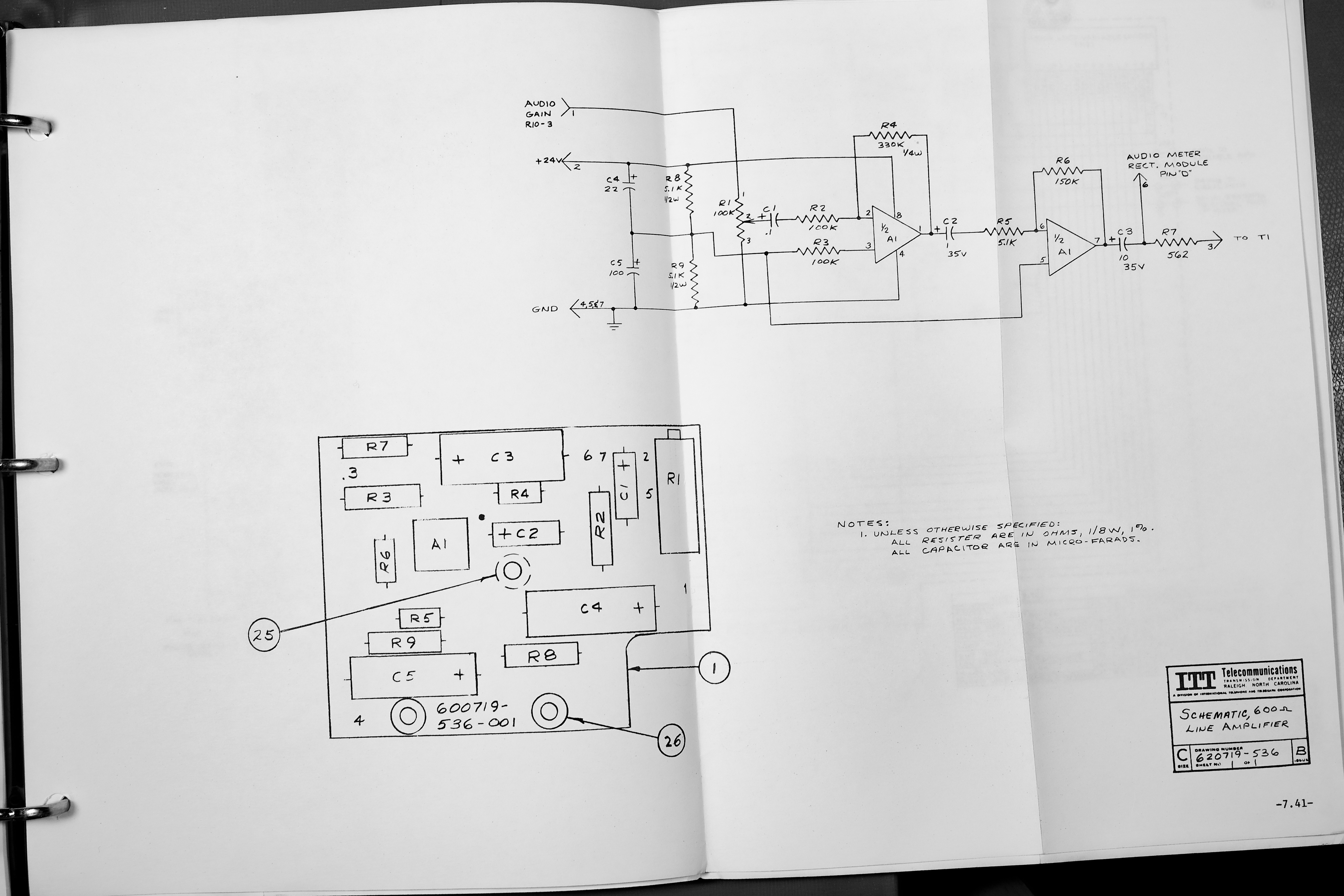
It seems this issue was known by Mackay Marine since a separate 600 Ohm line driver card in the frame had additional gain control to compensate for this, but they didn't bother to make the meter run off the un-levelled detector signal.
Scan-Tune Logic Issues
The Scan Tune Logic had several issues, the biggest was the use of a Ni-Cd battery to store the tuned frequency. This would be discharged fairly quickly if the tuning switch wasn't left in the middle position, and would then give garbage readouts until the tuning was swept through most of the range (wrapping each digit around).
The other issue was the poor mechanical qualities of the rotary encoder.
Poor AM Reception
The AM receiver didn't work super well for DXing, and the interaction with the AGC system was also annoying. It wasn't exceptionally bad, but it wasn't amazing either.
Power Dissipation Issues
The receiver ran hot, the power supplies would be very warm in normal operation, and this was mostly since the linear regulators were fed with around 2⨉ the voltage they would actually need. While good practice for the time, it is very inefficient.
Another large power drain was the synthesizer, which was also known to be somewhat unreliable. My specific one seemed to have gotten all the gremlins out and I never had a failure there.
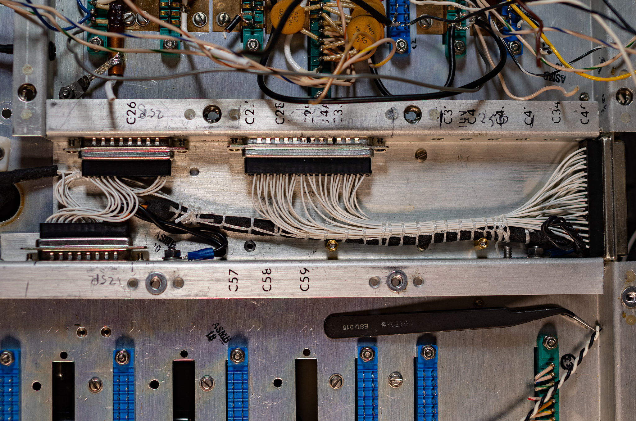
Internal Wiring (Stock)
The original back plane wiring was built to typical mil-spec standard for the era. The chassis is split along the middle, with card cages for the RF and Synth section. The middle is the "spine" and connects with coaxes and feed-through capacitors.

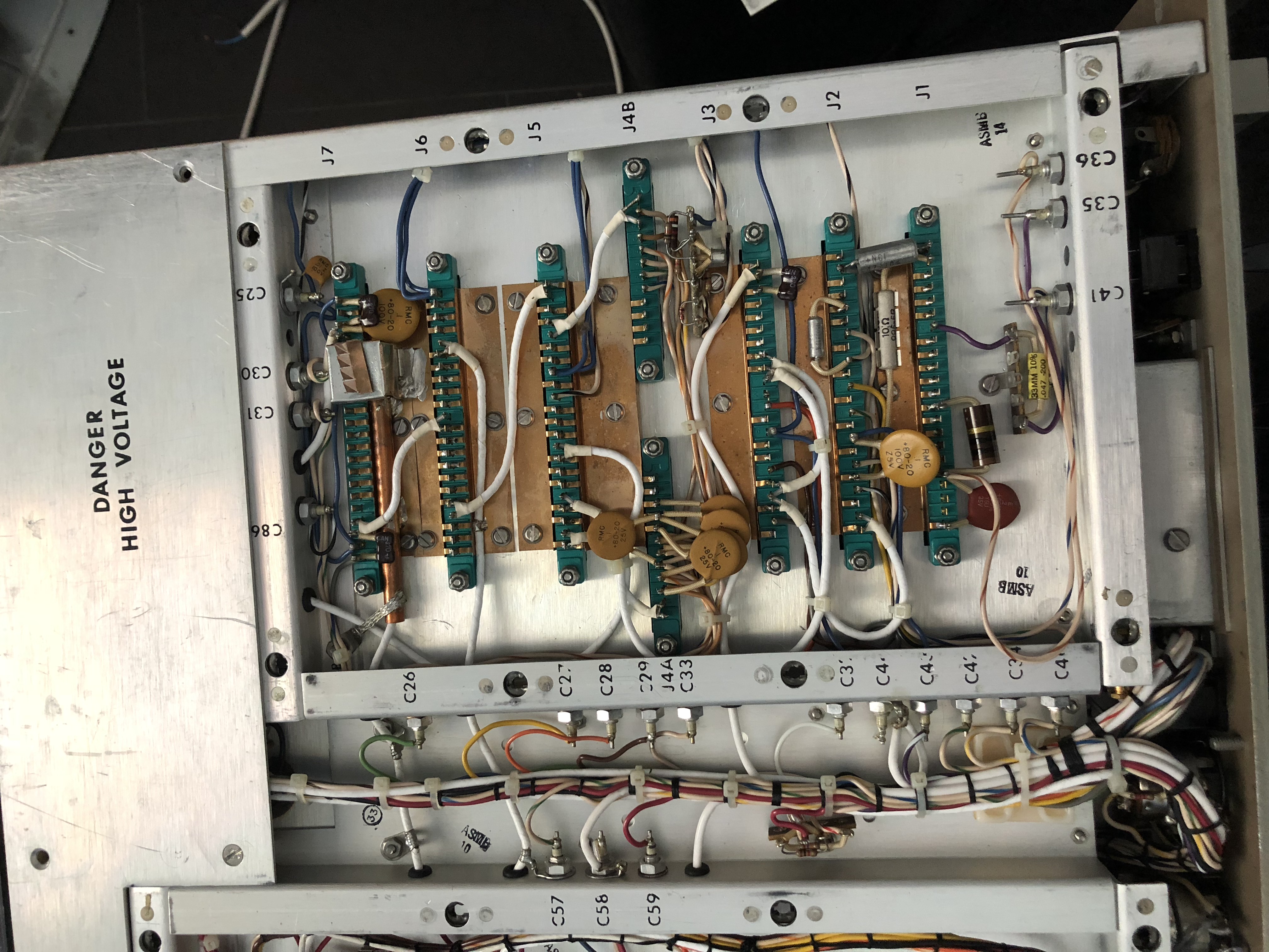
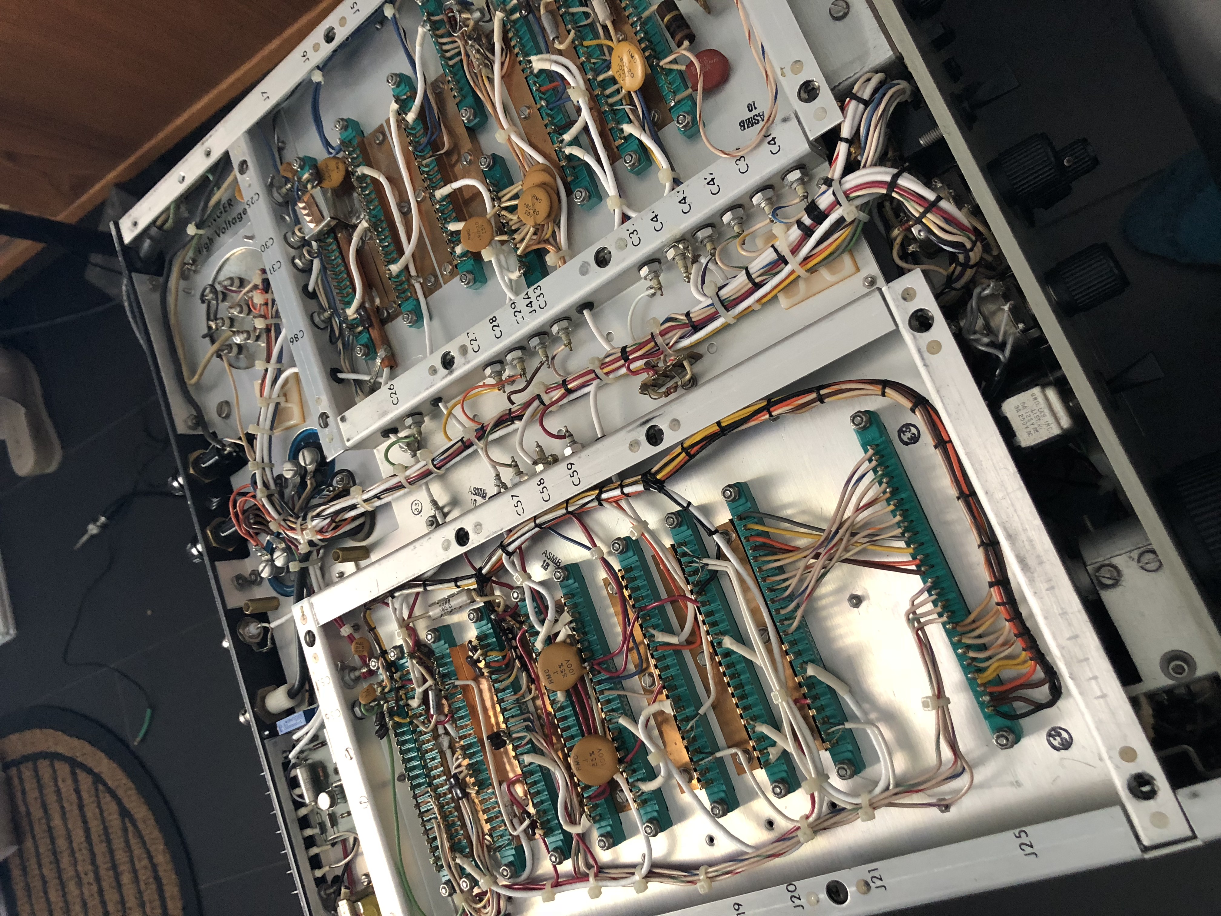
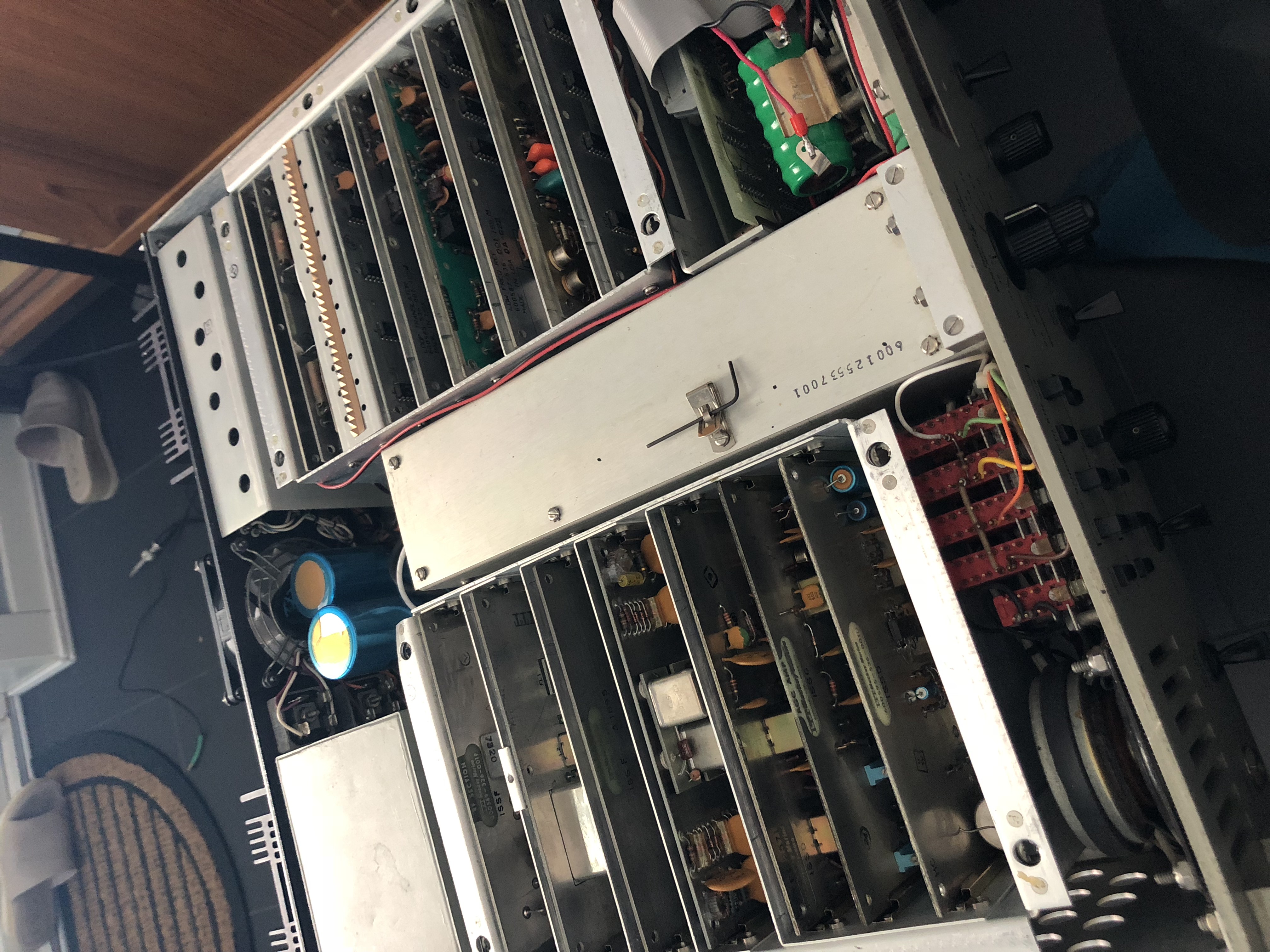
A few cards are mounted outside of the card cages, these include the power supplies, and an audio line driver card. This line driver card makes up for the volume control/line level issue.
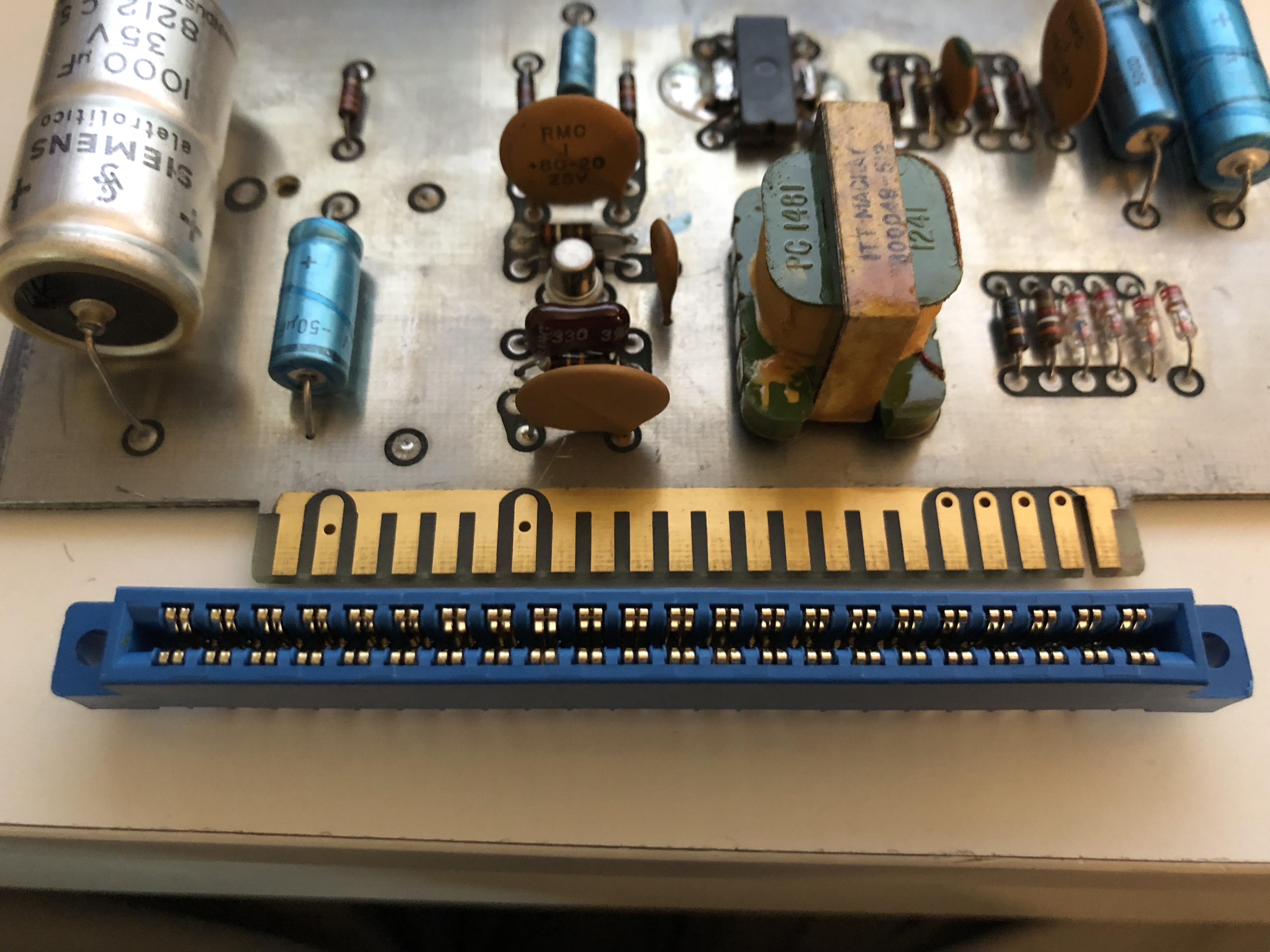
Most of the cards are 22 position 0.156" edge connectors, the only exception is the STL and IF filter cards.
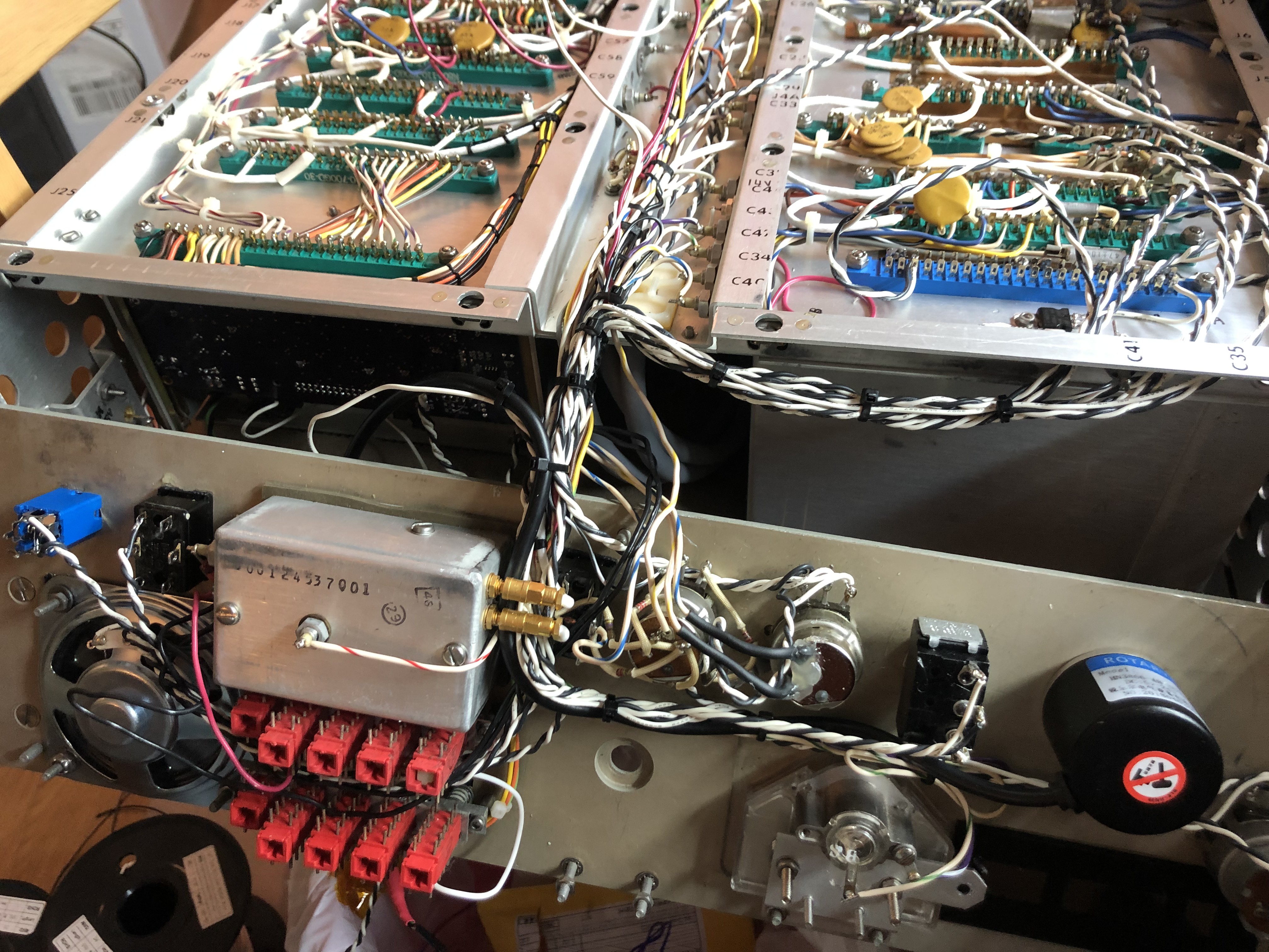
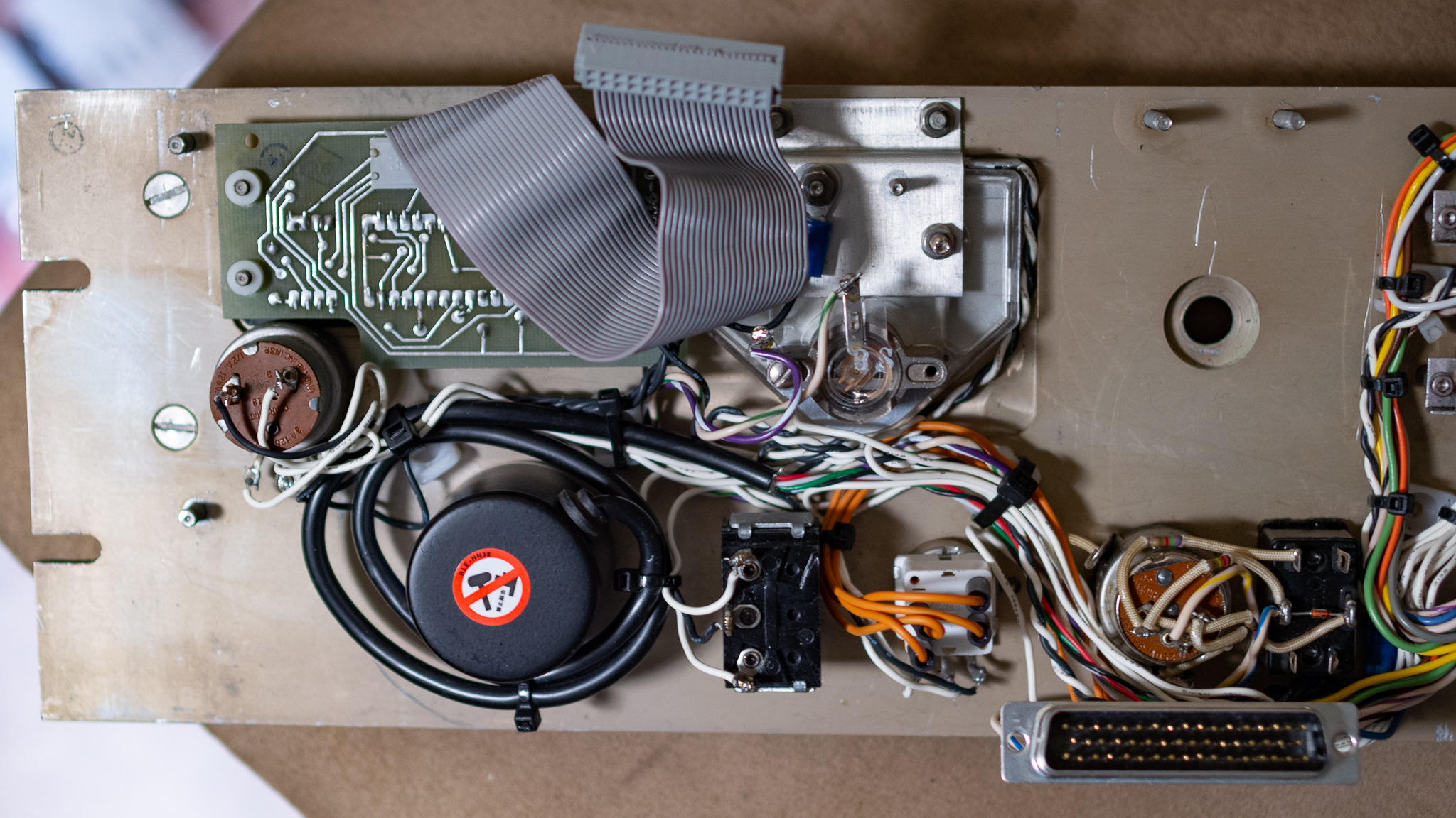
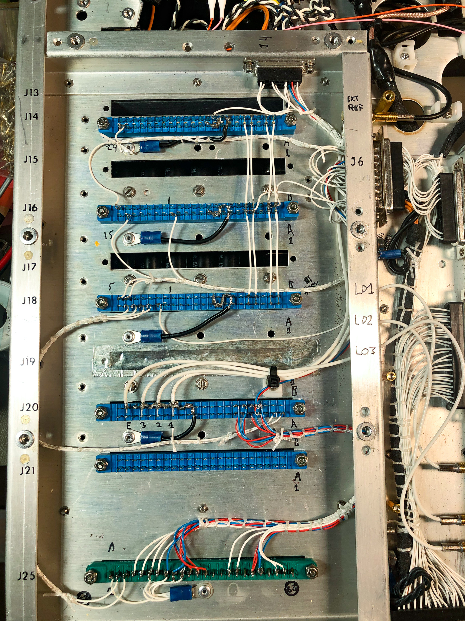
Above we see the horrible wiring for the front panel, which involves wires going everywhere making it impossible to remove cleanly. This was later entirely redone.
The metal box is the variable crystal oscillator for the beat frequency adjust, see below.
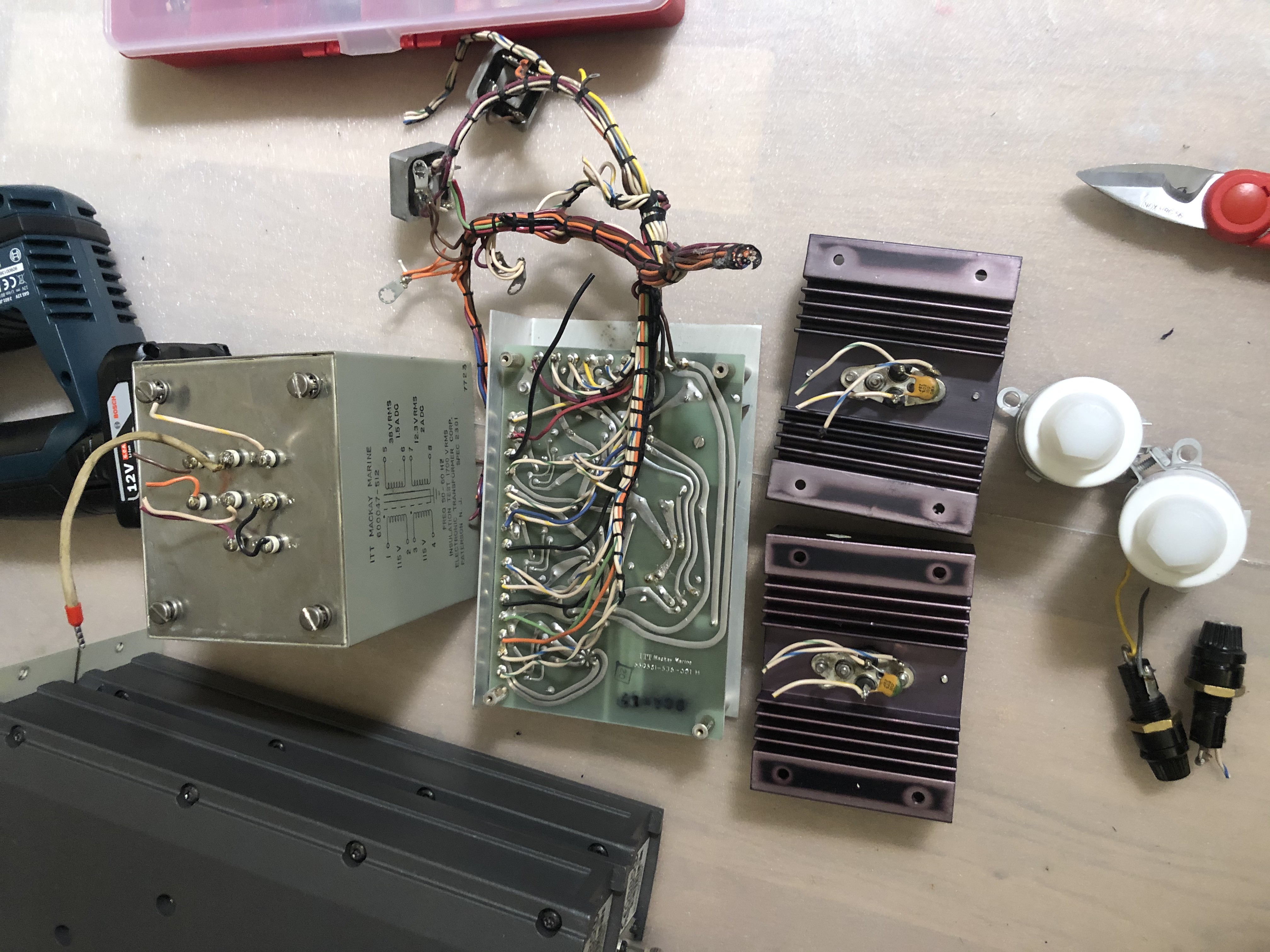
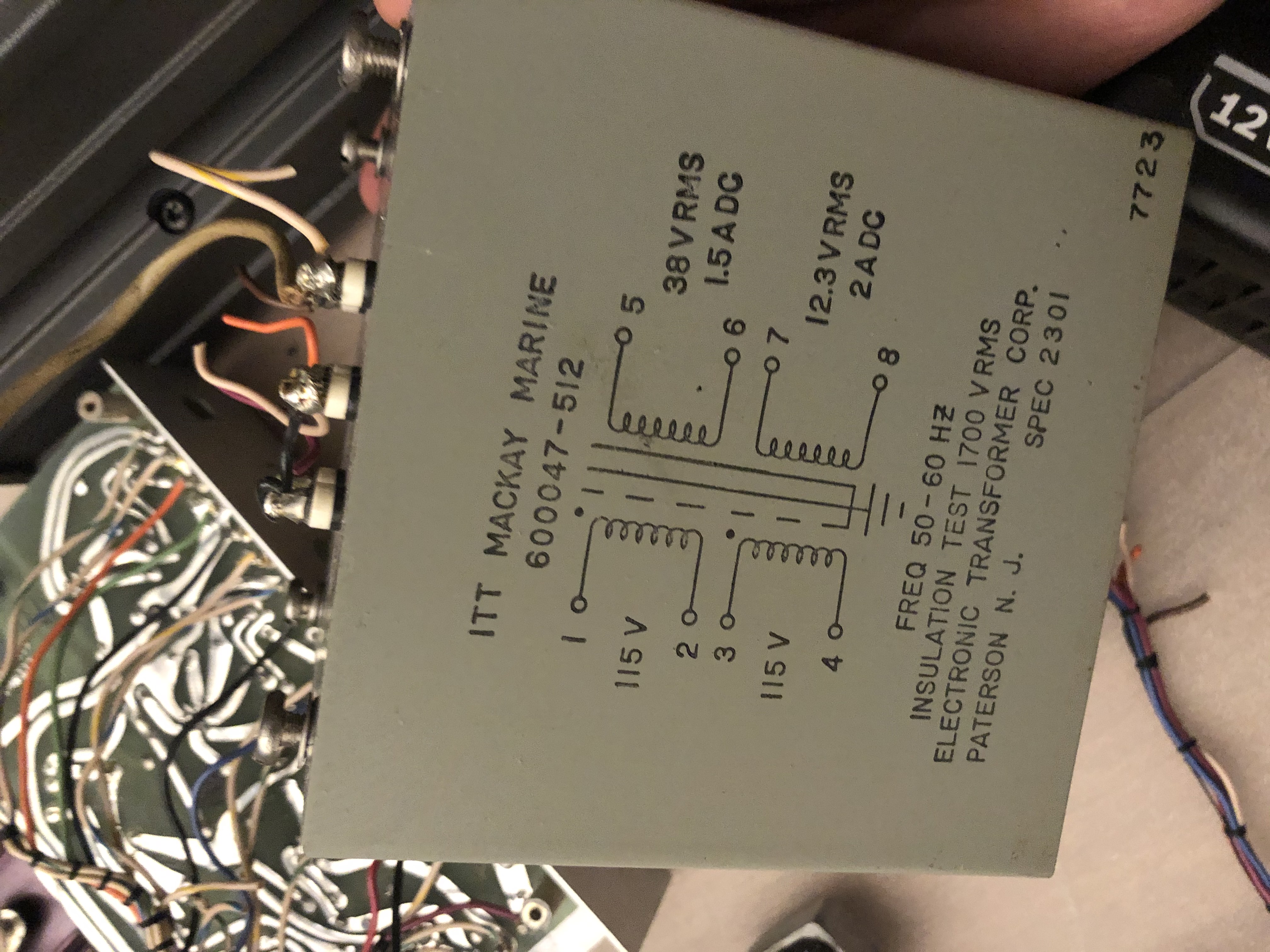
Power Supplies & Fan
The original radio basically just used 24 V internally, but a 12 V-ish DC bus was available and used to regulate the 5 V supply for logic. The regulators were obviously linear, and used 38 and 12 V AC transformer secondaries, yielding a very high tolerance for AC supply brownouts at the cost of very high idle power dissipation.
In a 2020 upgrade, these supplies were replaced with modern IRM-45 switch mode power supplies, and I used 24, 15, and 5 V supplies.
For my new designs I only use the 15 and 5 V supplies, and the 24 V supply was removed and replaced with an OCXO.
The fan was originally a typical 120 V fan and quite loud. I found a Noctua 80 mm fan could be retrofitted relatively easily (I also added helicoils to the rear plate so no nuts are needed). This can be powered from the original 12-ish V bus by tapping off the 5 V regulator near the STL cards.
Screws
The radio used DSUZ style quarter turn screws to keep the various lids on. These were invariably messed up by the time I got the radio. I later replaced most of these with M4 rivnuts where possible.
I also later made some small PCBs with soldered in brass inserts that were then riveted in to replace the old fittings. One of the top covers is possibly from a different revision of the chassis, since two screws appear to simply be in the wrong place there.
Otherwise, the radio is American so it uses mostly #4 and #6 screws and studs. These have mostly been replaced with metric equivalents where practical, so currently it's a mix.
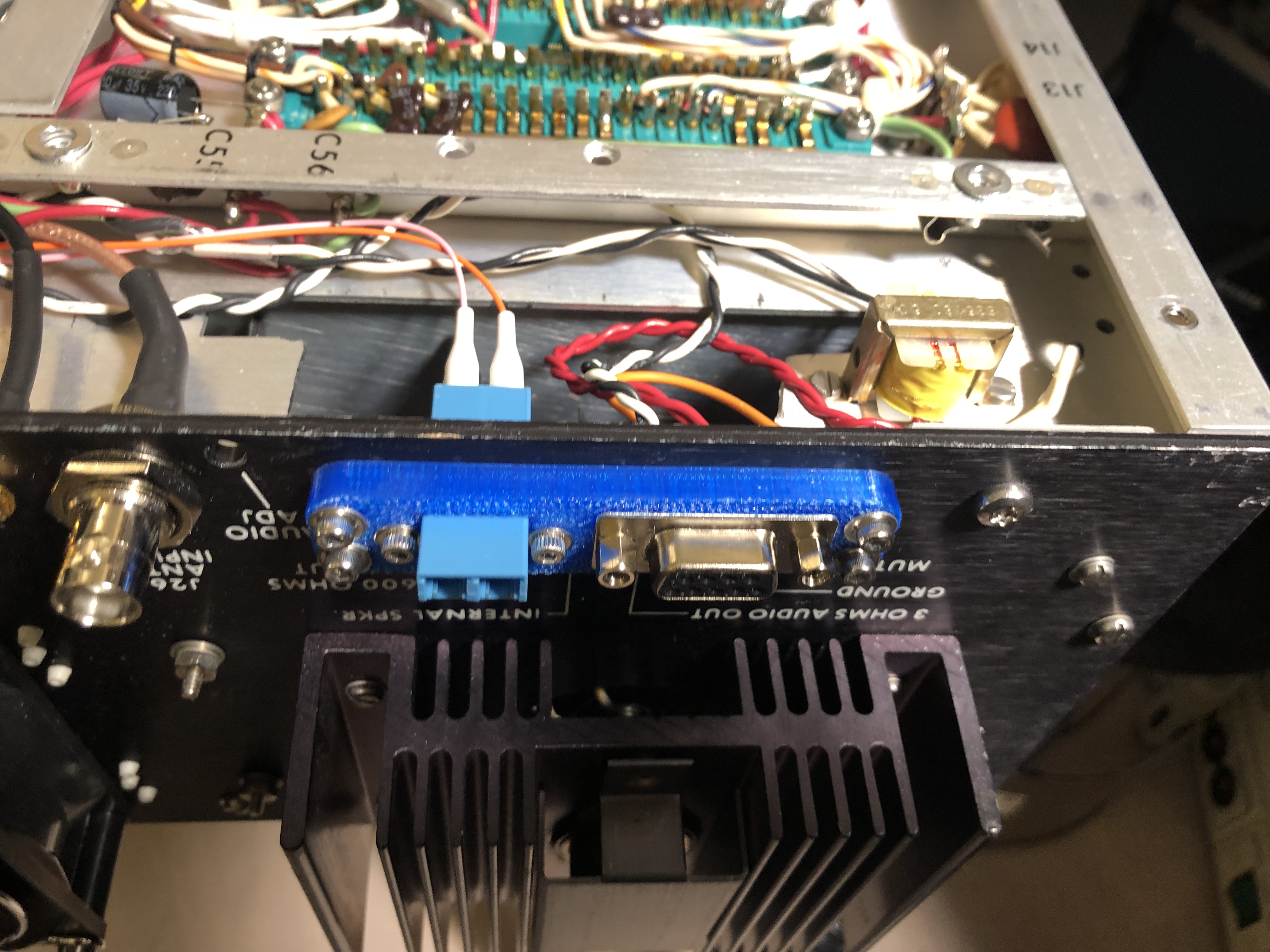
Re-Wiring (2020)
This is skipping forward a bit, but the front panel was later re-wired entirely in the middle of 2020 (didn't have much else to do). The purpose of this was to make it at all practical to remove the front panel, so I found that a 50 pin D-Sub connector was sufficient to route all the signals except the display.
This modification was done after the new DSP, Demodulator, Synth, and PSU cards were installed.
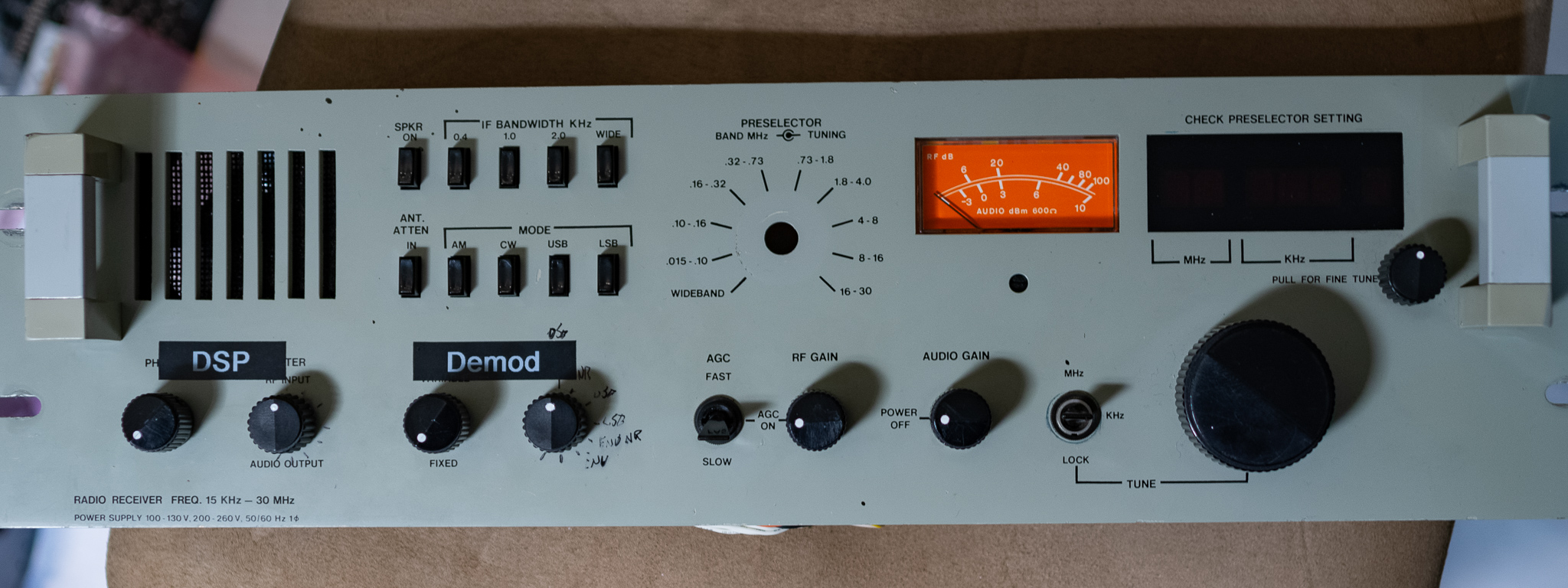
In addition to the 100 Hz step tuning via the knob, there is also a knob (upper left) that can be pulled out to activate a VCXO that allows for fine tuning between the 100 Hz steps. In my current iteration this switch and pot is wired to the Demodulator (not the synth, for practical reasons). The current iteration allows for tuning ±100 Hz over around 120° of rotation.
For the bottom row two types of knob are used, see the separate section below.
The combined volume knob and power switch has straight 230 V AC on it, this was done using the orange Radox® 125 wires, and this is in fact routed through the D-Sub. I elected to place these signals near one edge of the grounded chassis of the D-Sub with a set of ground pins guarding them. In the backplane the AC is wrapped in additional insulation and a grounded shield covers the wires.
I may move these to a standalone plastic connector later if I need to free up some pins in the main D-Sub.
The power switch/volume is a linear potentiometer with double pole switch rated for 230 V. The knob itself is a type with high viscous damping, and it simply generates a control signal for the DSP card that controls the volume.
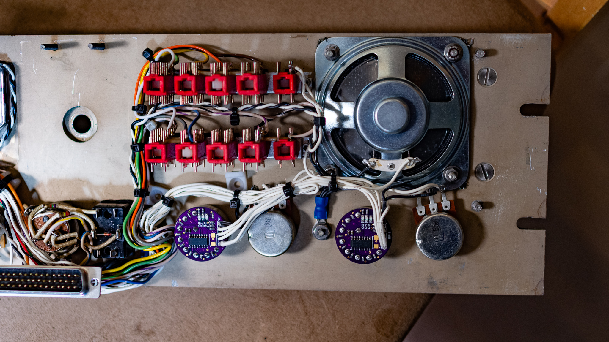
I used 8 position rotary switches to control the DSP and Demod cards (and perhaps more in future), so a set of small PCBs containing 74147 encoders converts the 8 position switch to a 3 bit BCD output.
I also added new PDA241 linear potentiometers where practical, these are relatively cheap "guitar" pots with strong viscous damping that makes them feel more expensive than they actually are.
The speaker was replaced as well, the newer type was selected for wide frequency response and high sensitivity. This speaker is driven by the DSP card currently, and it applies frequency response corrections to give a smooth sound.
Above the synth has been reduced to a single card, and the remaining space is filled with power supplies for 24, 15, and 5 V. The 24 V supply was replaced with an OCXO later.
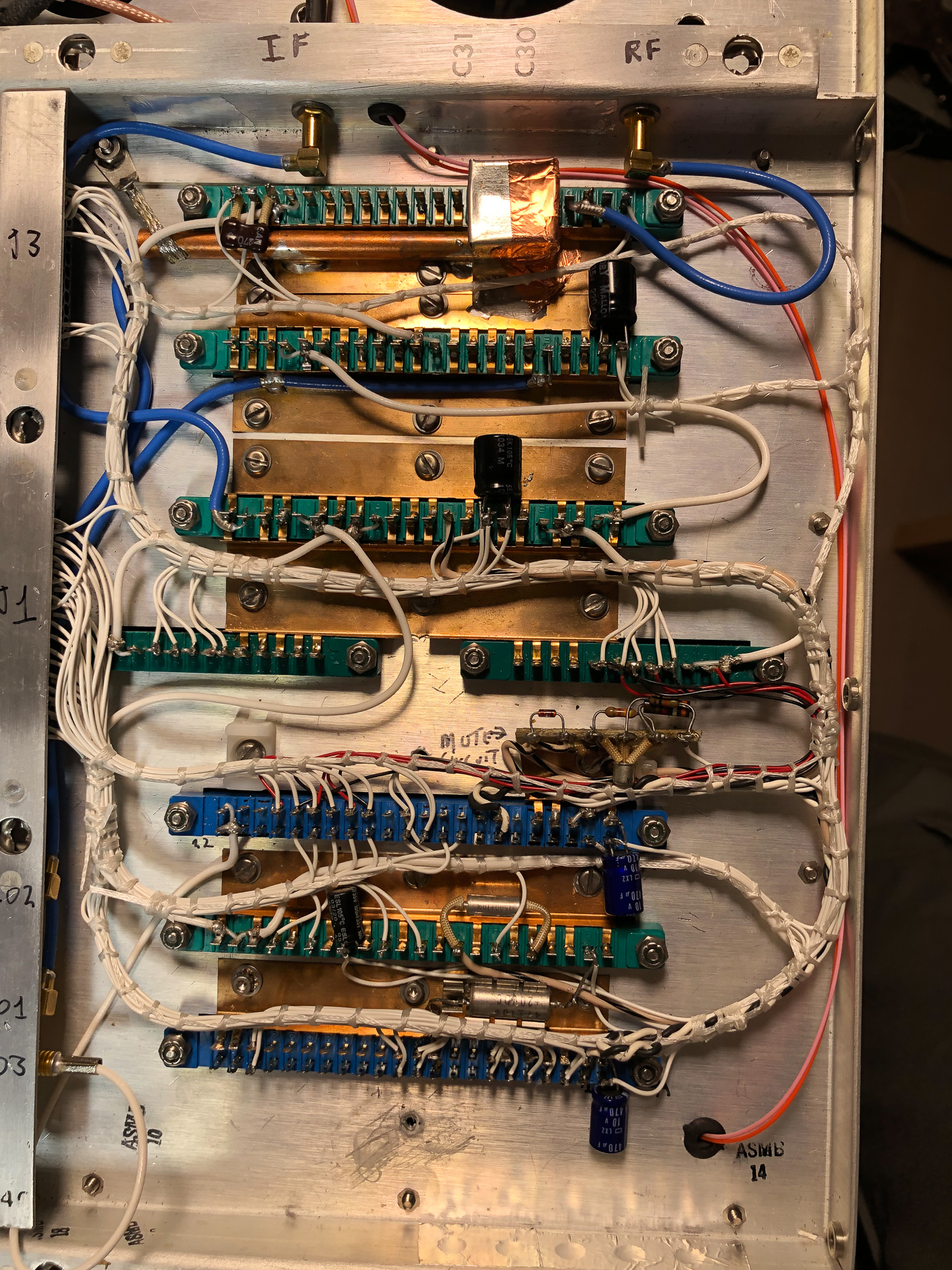
RF Section with new Demod and DSP cards. Pink/Red fiber optic cables visible to the right.
Knobs
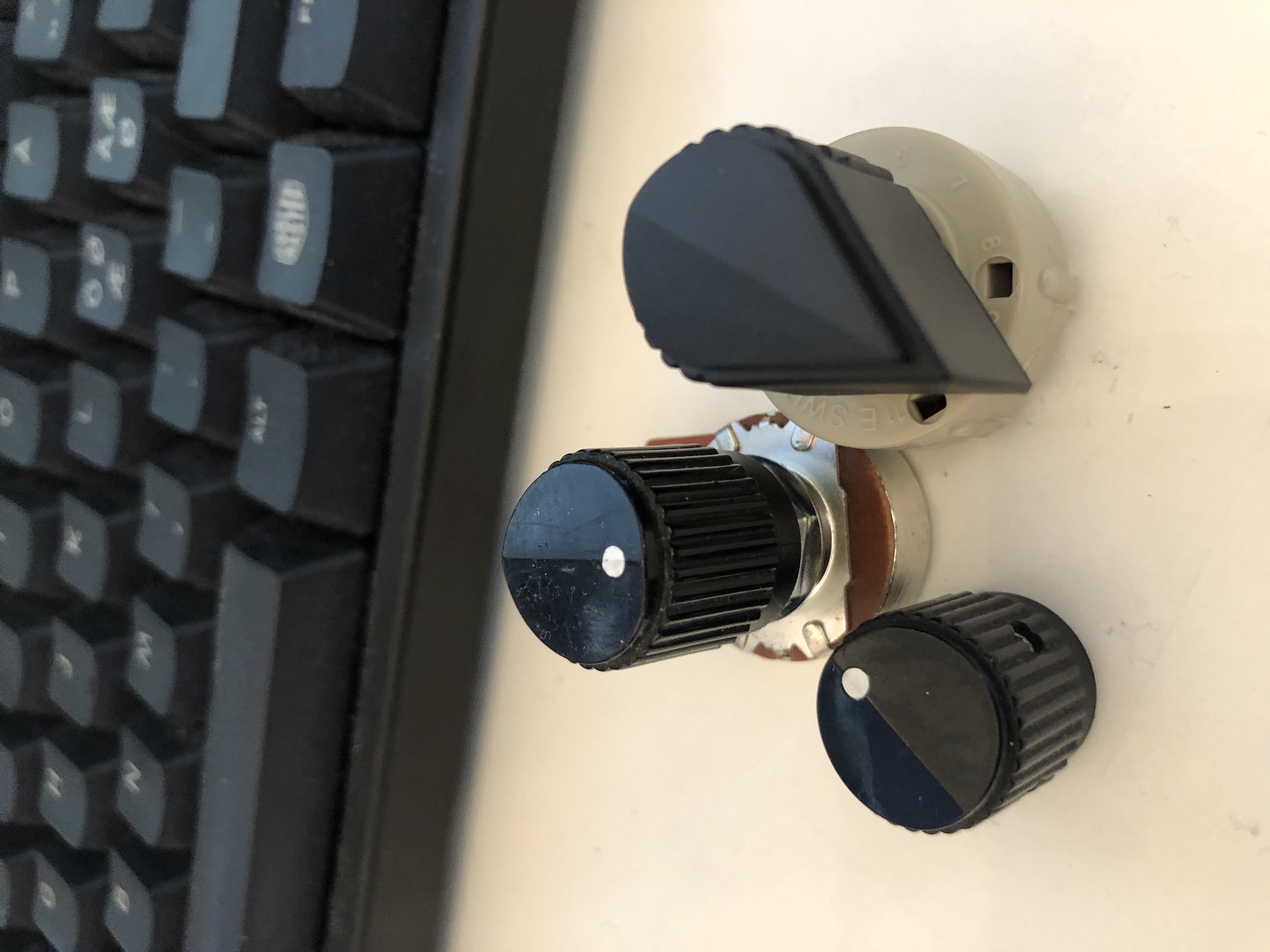
The front panel knobs did take some effort to match reasonably well once I started adding additional switches. Since I added additional rotary switches, I needed several new knobs.
The original knobs are mil-spec parts maybe by Raytheon, better known for their cruise missiles. These knobs have white indicator areas, these were worn out so I repainted them where applicable (these are clearly visible in the manual).
The series of knobs is an old mil-spec series, and the closest living relative I found was the Grayhill 11K50xx series of "fluted" nylon knobs, and the new rotary switches use the 11K5014-KCNB knob with a flatted shaft. An equivalent screw mount type was also used for the fine tune switch.
The key difference between this and the style used for the older ones is a slightly more aggressive knurling, and the Grayhill types lack the skirt near the base. The finish is also slightly shinier on the old ones.
In addition, the Grayhill knobs lack an indicator dot, so I mounted all the new knobs in a vice and milled a little pocket that I filled with white enamel paint.
I elected to use original knobs primarily for the potentiometers, and the new style knob for the rotary switches I added. This looks close enough to not be ugly, but also makes them slightly visually distinct. The 11K5028 was also considered but I thought it looked too big.
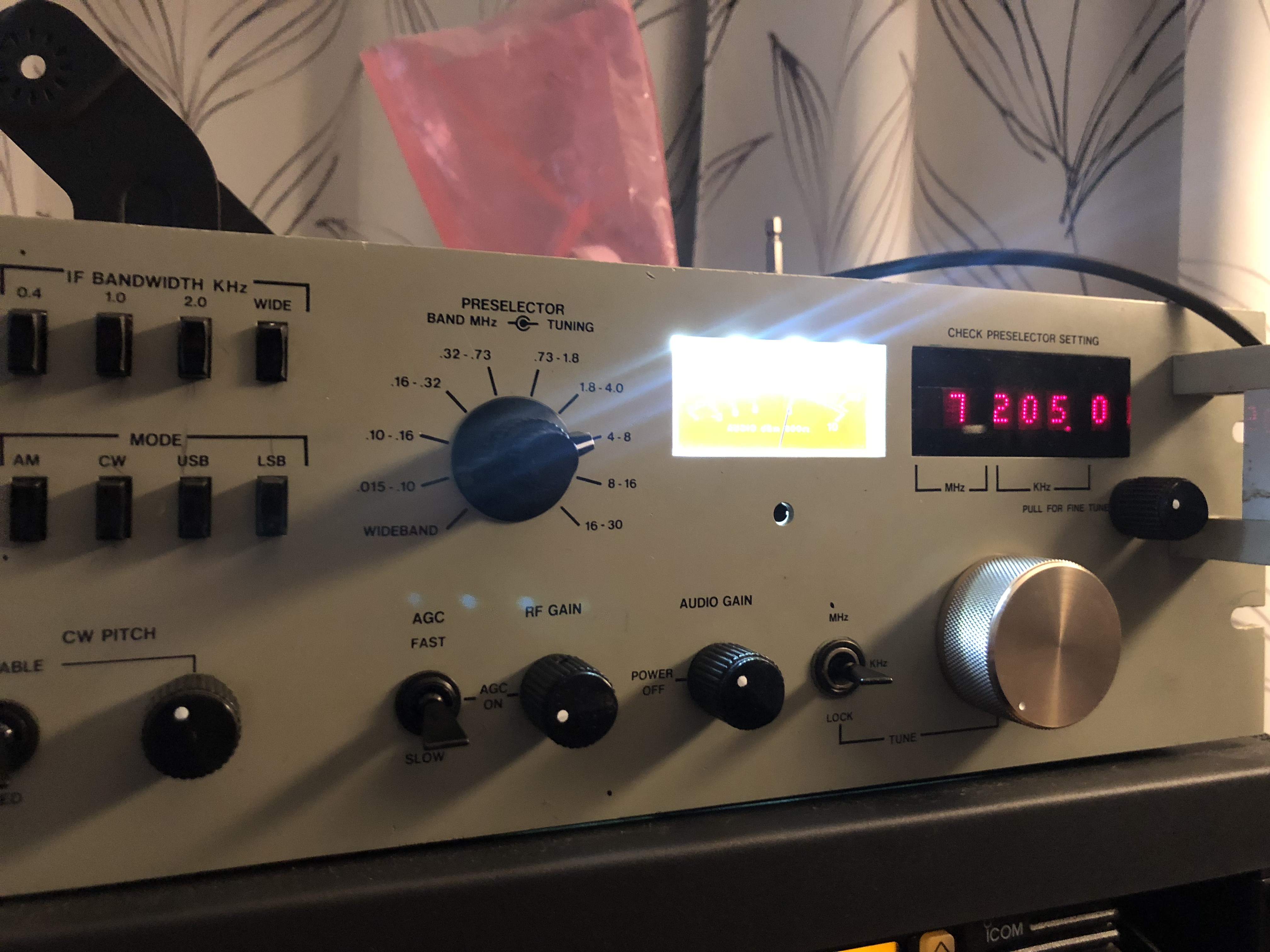
In the picture above I had mounted a large aluminium knob for the tuning, but I later went back to the original knob for better aesthetics.