miroGraph Chroma v3.3a

Some info on the miroGraph Chroma v3.3a NuBus video adapter.
Table of Contents
Overview
The card is a 12" unaccelerated NuBus card, using a few GALs, and a lot of 74ACT and F logic to drive what is probably a fairly common Bt473 or similar 80 MHz+ RAMDAC chip (the heat-sink is epoxied in place so can't tell for sure).
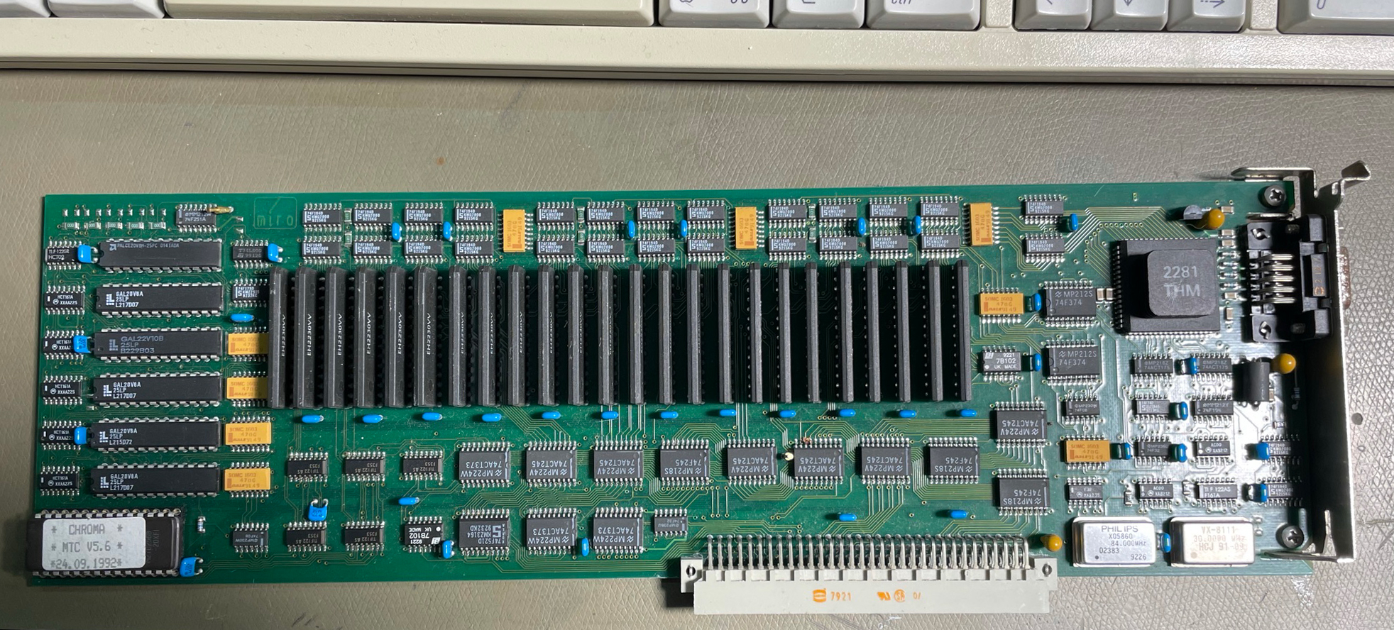
The card was built by miro datensysteme GmbH (lower case sic) around 1992, the PCB markings indicate it was designed in 1989.
The card was presumably designed for desktop publishing or similar uses, and was sold with a suitable Trinitron CRT monitor. The resolution is 1024⨉768@72 Hz, up to 24 bit, there is no resolution switching here.
A prior revision of this post identified the refresh rate as 75 Hz, it is in fact 72 Hz. This can affect monitor compatibility, many monitors will only do 60, 70, and 75.
The video output is non-standard, using a 9 pin female D-Sub connector. My card came with a pre-rusted connector, so I replaced it with one I had laying around.
From what I've gathered, miro didn't really design their own graphics cards, so much as license designs from Radius and re-brand/adapt them. It does look like this card is a miro PCB layout. It's a 6 layer board, which is pretty advanced for 1989.
My best guess is this card is based on the DirectColor 24, from pictures it looks like that card used a similar architecture and the specifications seem in line. This card seems to have fewer discrete logic chips on it, but that could be the result of increased use of GAL/PALs in the miro variant, or perhaps removing unneeded features.
The card uses 22 pcs TMS44C251 262k⨉4 bit dual ported video RAM chips as the frame buffer.
The DirectColor 24 was a 1152 x 882 card, while this is a 1024x768 card, but that would be a fairly simple modification to the base design.
Being a non-accelerated card, there is a significant performance benefit from operating in 8 bit mode (around 3⨉ faster, since it's CPU/bus limited).
Troubleshooting
My card didn't show up in the diagnostics when I popped it on and powered up, but no smoke was emitted. So far so good.
Suffice to say I spent a few hours figuring out why it was seemingly dead. I did notice some slightly sub-par reflow soldering work around the board, ICs were offset from their pads enough to not meet J-STD-001 class 3 for example. This is not usually a problem problem though.
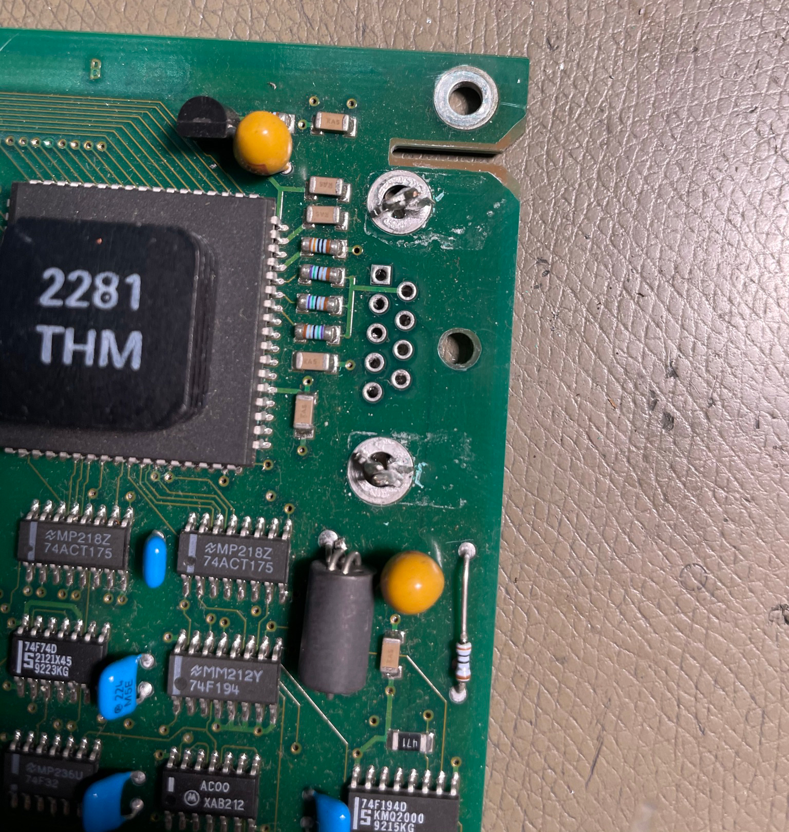
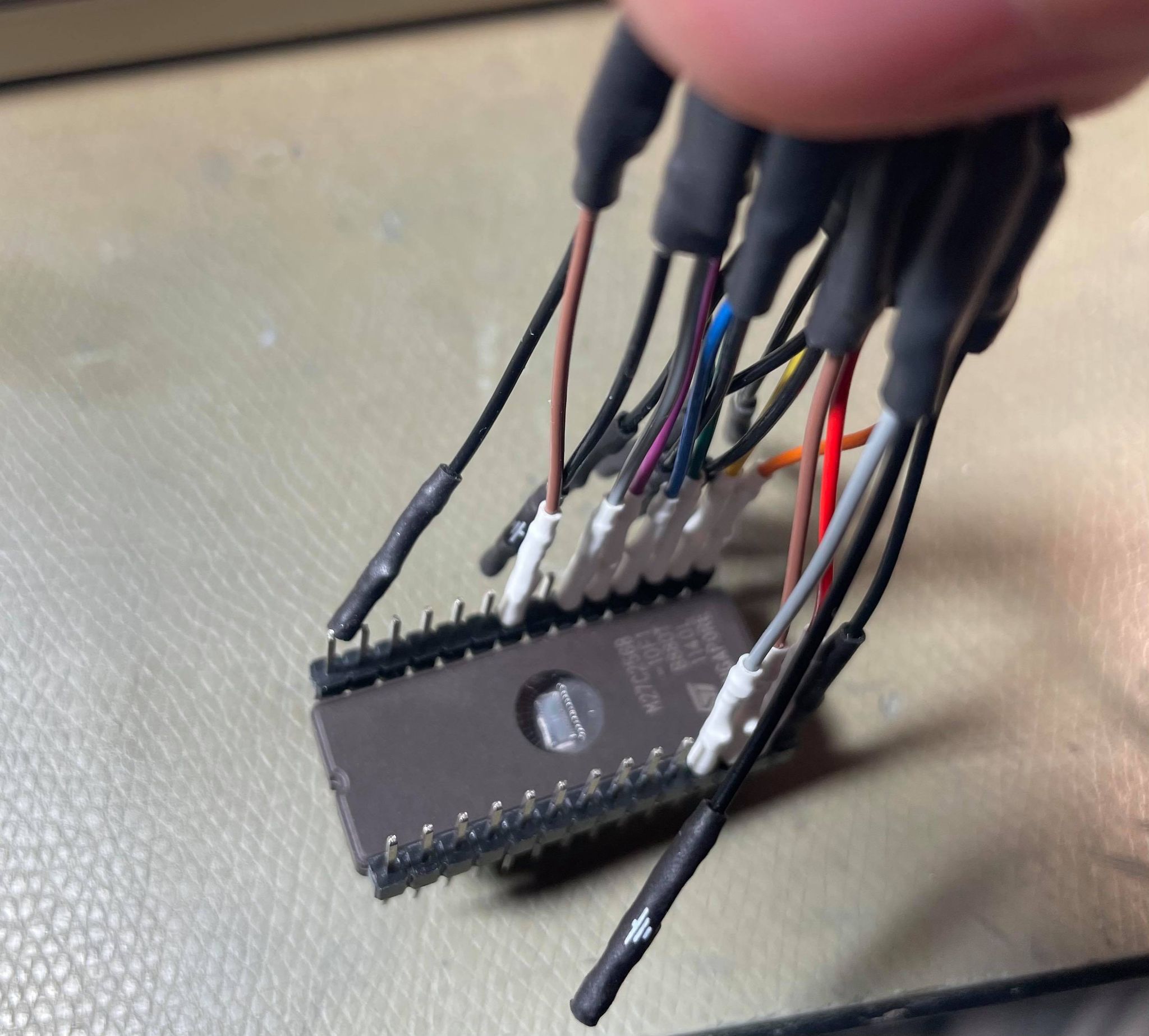
After doing some investigation I decided to instrument the ROM data lines and enable lines to see what happened upon startup.
When a NuBus computer starts up, it interrogates each card slot to get the declaration ROM contents, which tells the computer what card it is, and for graphics cards it also loads the driver from the ROM.
Instrumenting the data and enable lines, I saw no activity except the OE_L line was being pulsed a few times. Since the CE_L (chip enable active low) line was always high, these pulses did nothing.
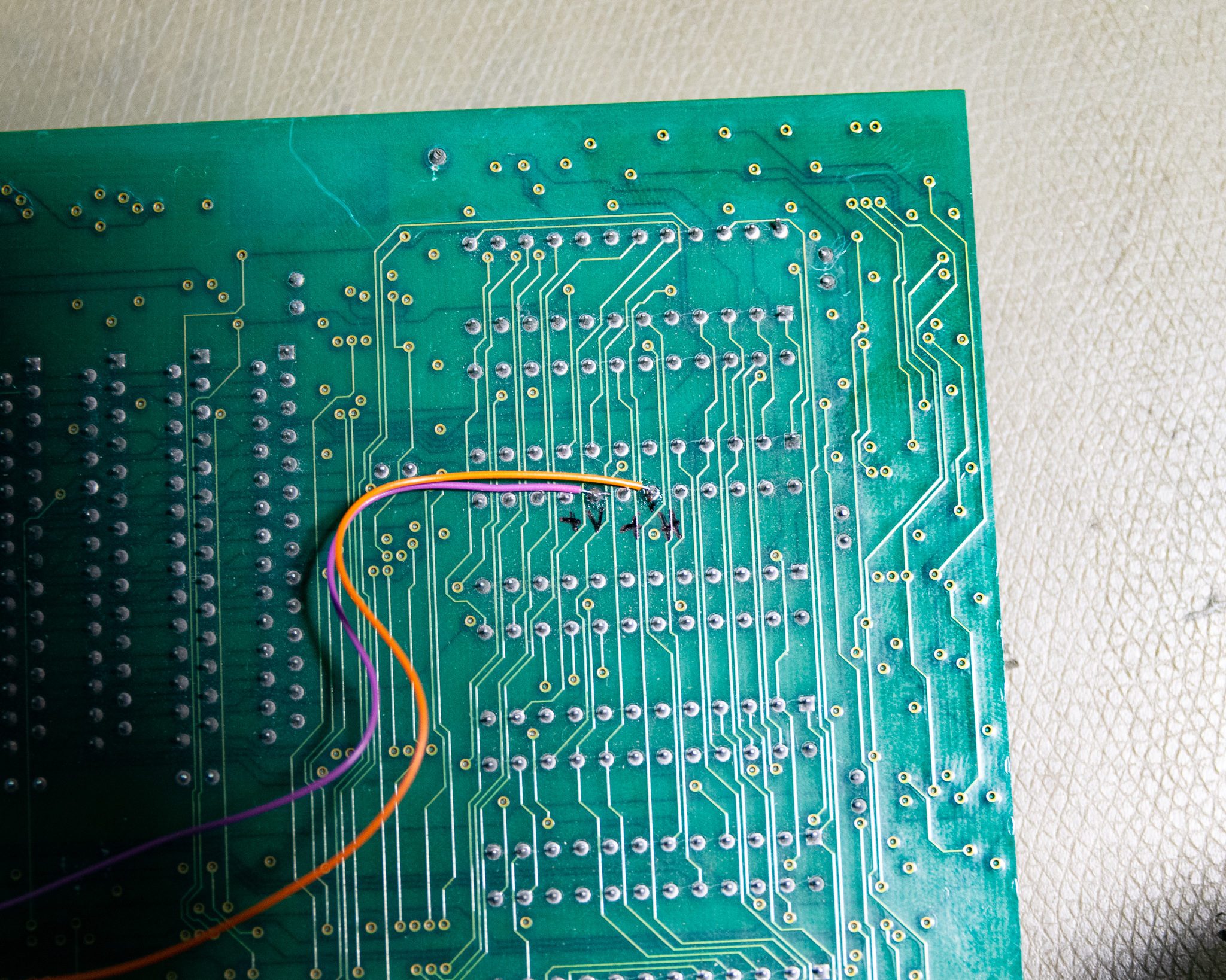
Looking at where the CE_L line went, I had to trace an internal layer through the board, including removing several ICs to be able to visually see the trace as it went right across the board, finally ending up at the D-Sub pin 7. This was the last place I would have looked for it (I certainly checked every other IC pin to try to find it).
As it happens, this card simply is not possible to use without a monitor connected, presumably the monitor grounds out this line when connected. When the monitor is missing upon power-up, the card is basically non-existent to the computer since the ROM is disabled.
I fixed this by declaring pin 7 to be a ground pin by shorting them out at the connector, this also let me use that pin as a ground for the video lines.
ROM
The original ROM for my card is a 27C256B (200 ns speed grade), the dump is here: Chroma MTC v5.6, mid 1992 date
Note that being a Radius based design, the ROM is scrambled somehow (data and/or address lines are swapped between the ROM and computer). Therefore, the contents are not really human readable like the RasterOps board I dumped earlier. Looking at other Radius dumps this file follows a very similar structure.
As part of troubleshooting, the ROM dump has been verified by burning a new ROM to use with the logic analyser and for initial testing.
Driver
I was able to obtain the driver after some time, it's simply a control panel that lets you select a specific gamma correction for the video output.
The miro Mac driver archive including the Chroma package is available here: miro_mac.zip, this archive was provided by Maik from mirosupport.de, thanks!
The files are all encoded so you'll need Stuffit as usual to unpack the files.
It seems that the ROM was updated a lot (v5.7 from late 1992 is the latest I've seen around).
The Chroma driver archive contains two full colour demo images called miroGirl.PICT32 and miroRose.PICT32.


This is kind of odd, it also includes a pile of shareware and freeware programs demoing Mac graphics capabilities.
Video Output
The card uses standard RGB video outs, and features sync on green, as well as sync on red and sync on blue (probably an artefact of the RAMDAC, not intended for use).
There is a CSYNC output by default, it's an XOR style signal suitable for many types of monitor. In my experience a lot of monitors claim CSYNC support but fail when it's applied, for example the Dell 1800FP worked but had unstable vertical synchronisation (random vertical image shifting), and didn't seem to use the SoG signal. The Dell 1504FP didn't like the CSYNC+SoG signal much either. As usual, the Philips 20V5Q had no issues at all.
The card only operates at 1024⨉768 @ 72 Hz (60 kHz HSYNC). There is no resolution selection in the driver, and it will boot-splash a monochrome miro logo screen when it's powered on but not initialised.
Pin 5 is 12 V, via a small current limiting resistor. Pin 9 is also 12 V, but looks like it might be a sense line (monitor pulls to ground?). The straight 12 V output could be to wake up the monitor when the machine is powered.
If you have a SoG capable monitor, you can use pins 1, 2, 3 as RGB, pin 7, and 8 as grounds. CSYNC is pin 4 if needed (by convention, connect to HSYNC line).
Alternately, see below for how to make it work with any VGA monitor.
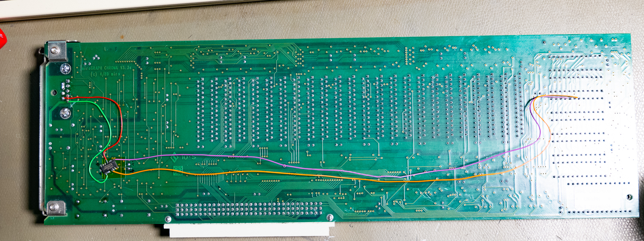
VGA Output Modification
Modification for VGA output is fairly simple with this card. The card generates all required signals internally, so you just need to wire these to the output and standard VGA sync is available. This was possibly left over from the original Radius design and simply retained, or it could be these signals are used internally and are needed anyway. After doing this mod all my LCD monitors were happy with the signal.
To implement this I decided to modify the original 9 pin pinout, as shown below. A resistor on the top layer connects pin 5 to +12 V, I cut this resistor. I also cut the trace going to pin 5 to re-use that pin. Pin 7 and 6 were shorted together to disable the monitor-detection feature in the card. I could then use pins 6-8 as ground returns for the RGB signals.
A 74HC14 was used to double-invert the signals to isolate the GALs from whatever load the monitor puts on the signals. After taking the pictures and testing I secured the wires with a few dabs of epoxy.
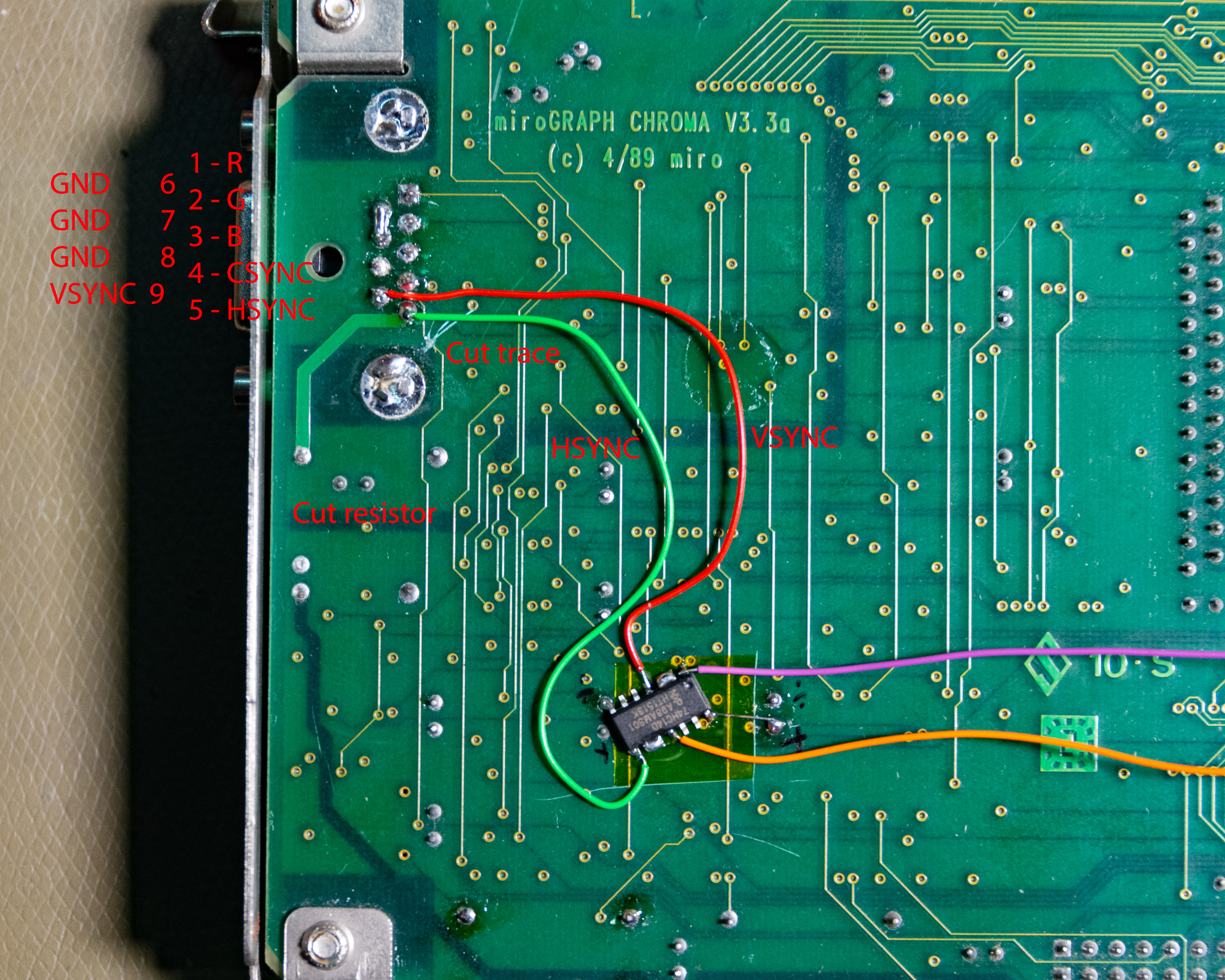
I ended up with the following 9-pin to VGA cable pinout, after modifying the card as shown above:
| Name | Pin no. 9 pin |
| Red | 1 |
| Green | 2 |
| Blue | 3 |
| CSYNC | 4 (not used with mod) |
| HSYNC | 5 |
| VSYNC | 9 |
| GND | 6, 7, 8 |
Note that the ID0 line in the VGA connector (pin 11) is by convention (not sure if by specification) used as a card presence detect line for LCD monitors.
By shorting this to ground, LCD monitors will settle into power save mode, instead of showing the "check cable connection" screen.
Note that since this card uses a 9 pin connector, it would actually be fairly trivial to replace the PCB mount 9 pin with a solder cup style VGA connector.
Then you could simply wire the required pins to the PCB to get a standard VGA output.