Repairing a Symmetricom X72 Rb Oscillator

The Symmetricom X72 is a very compact high quality Rb oscillator, I bought a broken one hoping the physics package wasn't broken.
I won't go through all of how the X72 works, since at the time of writing I've only just powered it up and checked the discrete status and frequency outputs.
The unit has a clipped on RFI shield for a top lid, and uses a very annoying 26 pin high density Molex connector for all I/O.

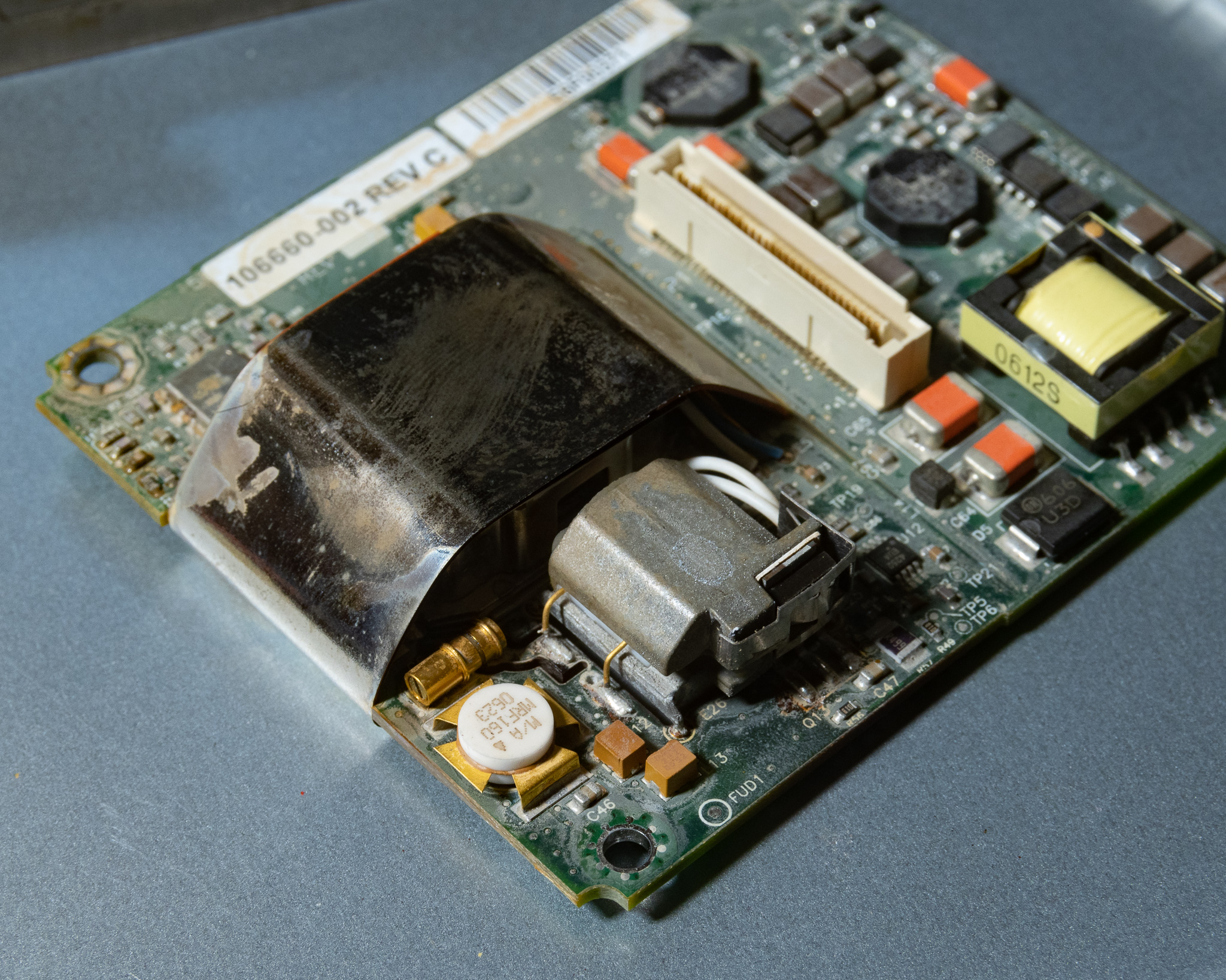


As supplied it was quite dirty inside, and even after a soaking in IPA and ultrasonic it still looked dirty.
Troubleshooting
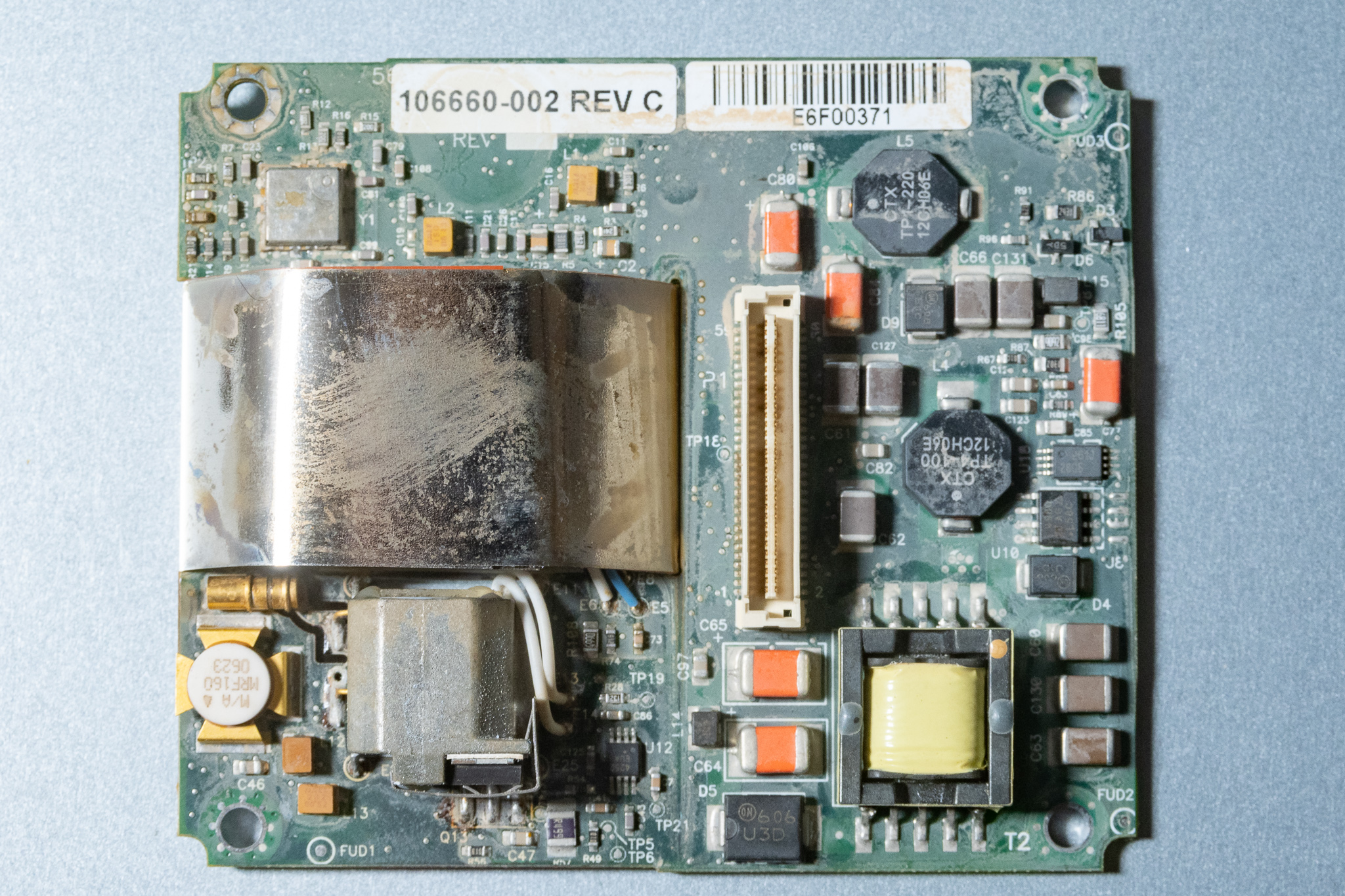
On receipt I soldered some wires to the top processor board to apply the external 10-32 V DC and see what happened. Fortunately it was a dead short. I quickly figured out that all the power runs through the board to board connector and into the DC/DC converter that takes up half of the bottom board.
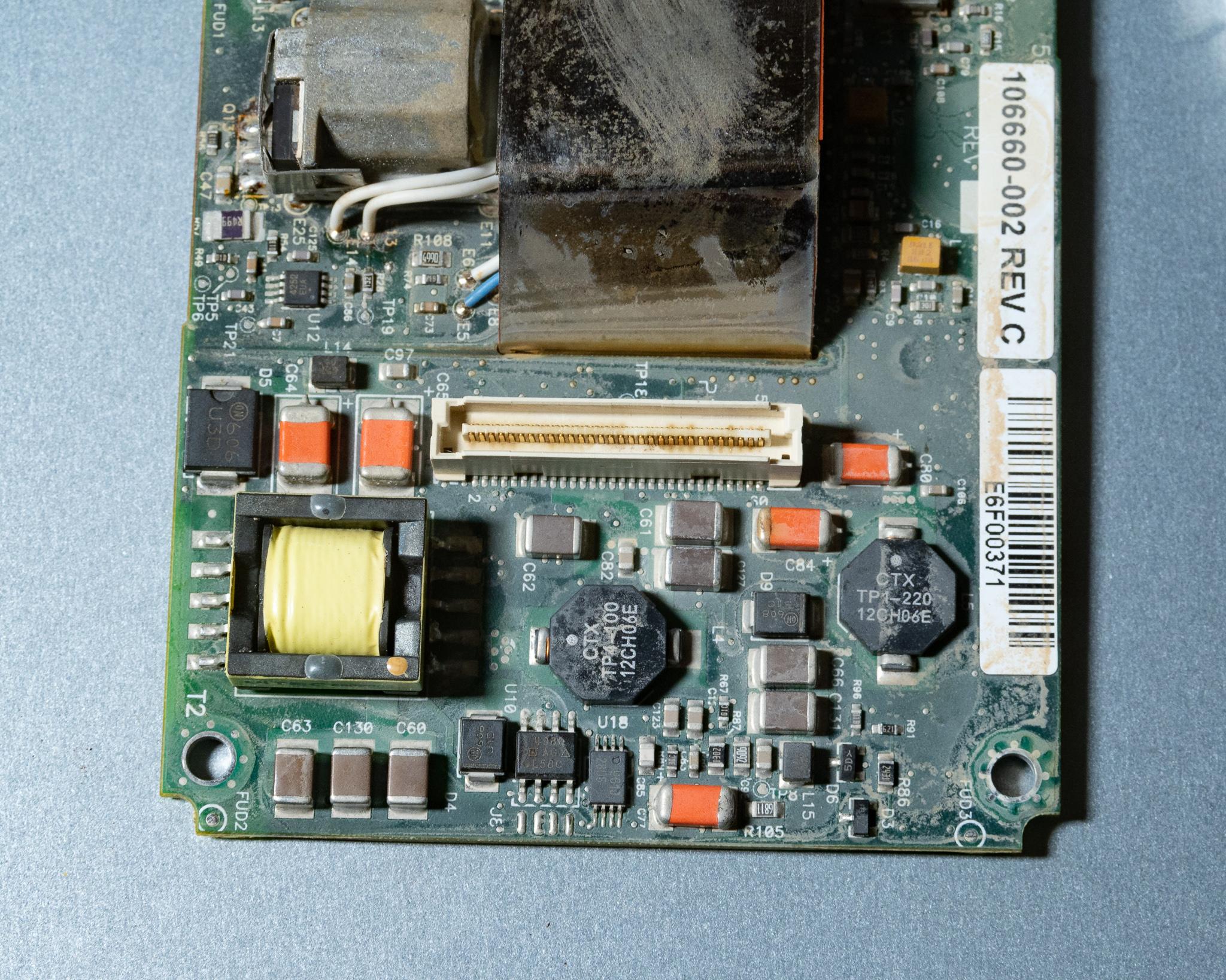
Using a high resolution multimeter to measure resistance to ground I determined that everything on the DC input was shorted with a resistance of ~200 mΩ to ground. Taking an educated guess, I desoldered the SO-8 IC marked U10 and the short went away.
It took me a while to figure out what this component actually was, the U10 marking was confusing but it turns out this is a KI4980DY dual N-channel MOSFET. Only the left side of the transistor is used, and the pins used are: 1:Source, 2:Gate, 7/8:Drain. The ratings are around 3 A DC and 80 V tolerance. U18 is probably the regulator IC.
I swapped it to what I had laying around, and used an IRF7343, but you could hack in almost anything.
On power-up it made weird noises and was clearly pulsing on/off. I figured it might be hungry for power, so I cranked up the current limit and the transistor blew up!
The output of the DC/DC is the big SMC packaged diode to the left. I figured that was the only output, so I decided to skip fixing the DC/DC temporarily and just power it directly. I obviously wanted to be careful, so I put in 5 V initially, then probed around and there was something happening on the main board, but most of the logic supplies seemed to be very low.
Cranking the voltage up slowly to 8 V seemed to increase the current consumption, and it shorted out pulling ~1.5 A at 5 V. Spraying IPA on the board when powered revealed that all the power was dissipated in the two orange tantalum capacitors near the rectifier diode.
I tacked in a 100 µF electrolytic and fired up the DC/DC section again, which looked promising until it blew up. Though this one was on me for putting in the electrolytic backwards!
Putting in a new one the right way around I saw a power consumption of around 20 W, which then ramped down to ~5 W. When increasing the voltage I saw a decrease in current, indicating correct operation of the DC/DC.
The regulated output voltage of the DC/DC turned out to be 17 V.
With this working I also saw reasonable voltages for the logic section, mostly 5 V, and a 60 MHz sine wave signal was present in various locations.
After a few minutes I was also rewarded with a lovely purple glow:
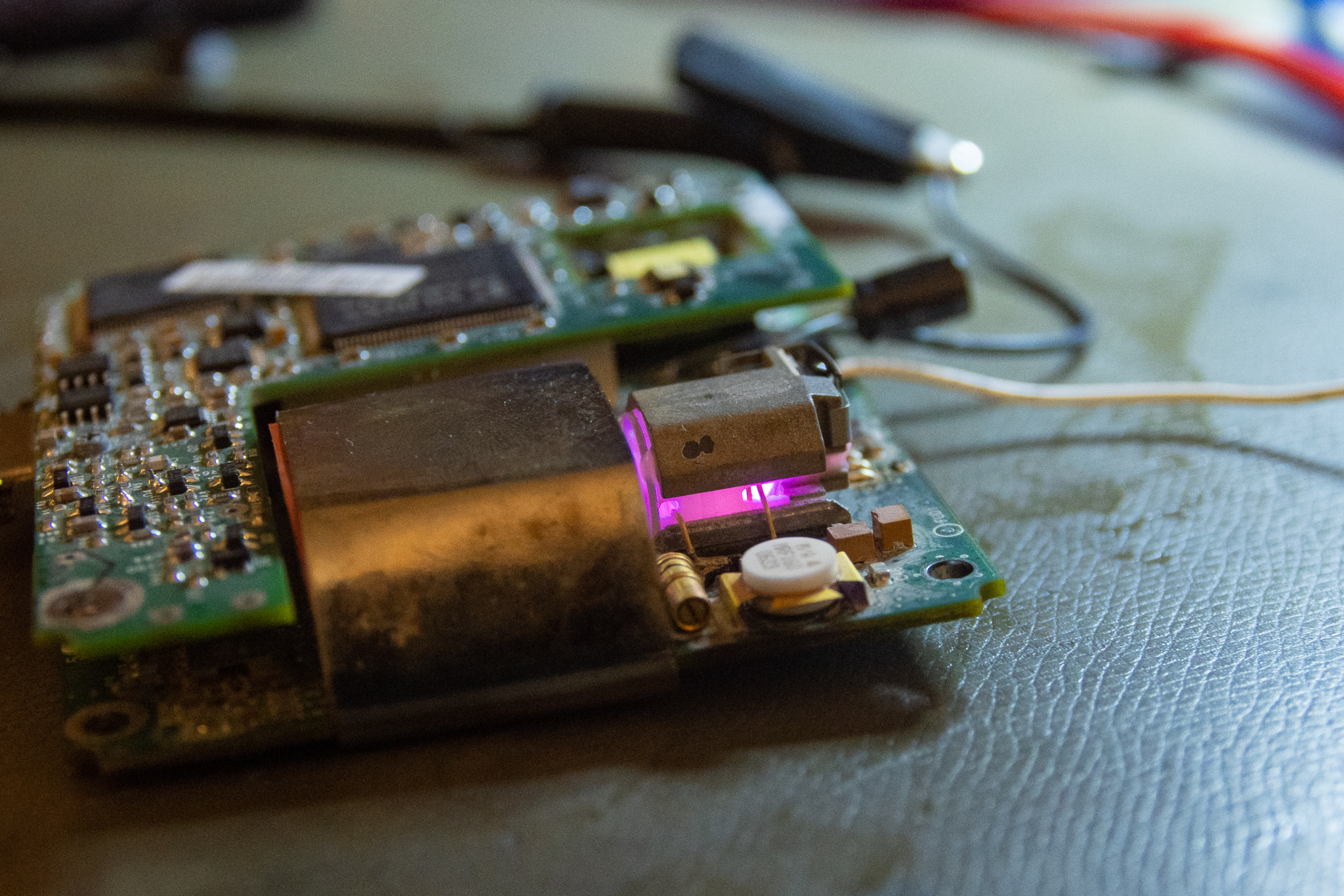
Lacking the appropriate adapter or connector, I simply probed the connectors pins and found the expected 10 MHz sine wave, a 60 MHz sine wave, a 60 MHz square wave, and the LOCK signal was low, indicating a lock. I was also able to verify that the SERVICE output was not indicating any fault.
Locking seemed possible even with very strong LED lighting, though stability is likely improved by keeping the lid on.
For repair I would suggest a case D (7343) 25 V or higher 33 µF or higher modern polymer tantalum. I replaced them with some tantalums I had laying around marked 336E, which corresponds to 33 µF/25 V.
Electrolytics will work just fine for testing, but for long term use this will cause problems due to the high operating temperature of the electronics.