Rohde & Schwarz GD801 Directional Coupler

Someone gave me two of these couplers, couldn't find too much about them online.
The GD801 is labelled as a MESSRICHTKOPPLER, or a directional coupler. It's a 4-port device, two sample ports with one factory fitted with a terminator.
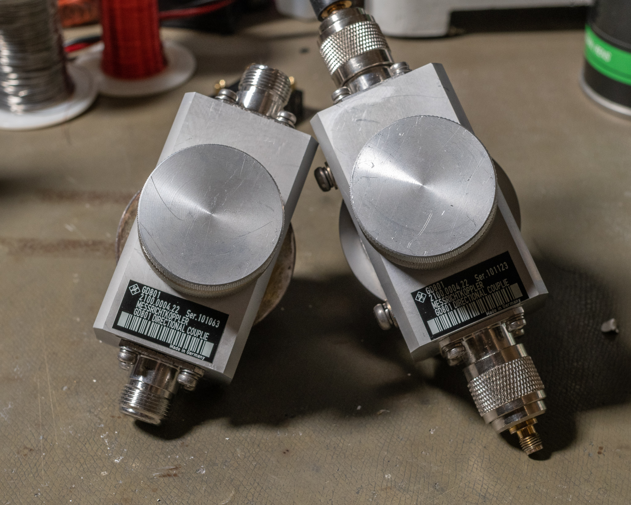
From the markings and manufacture they are obviously used as part of some type of TV transmission system.
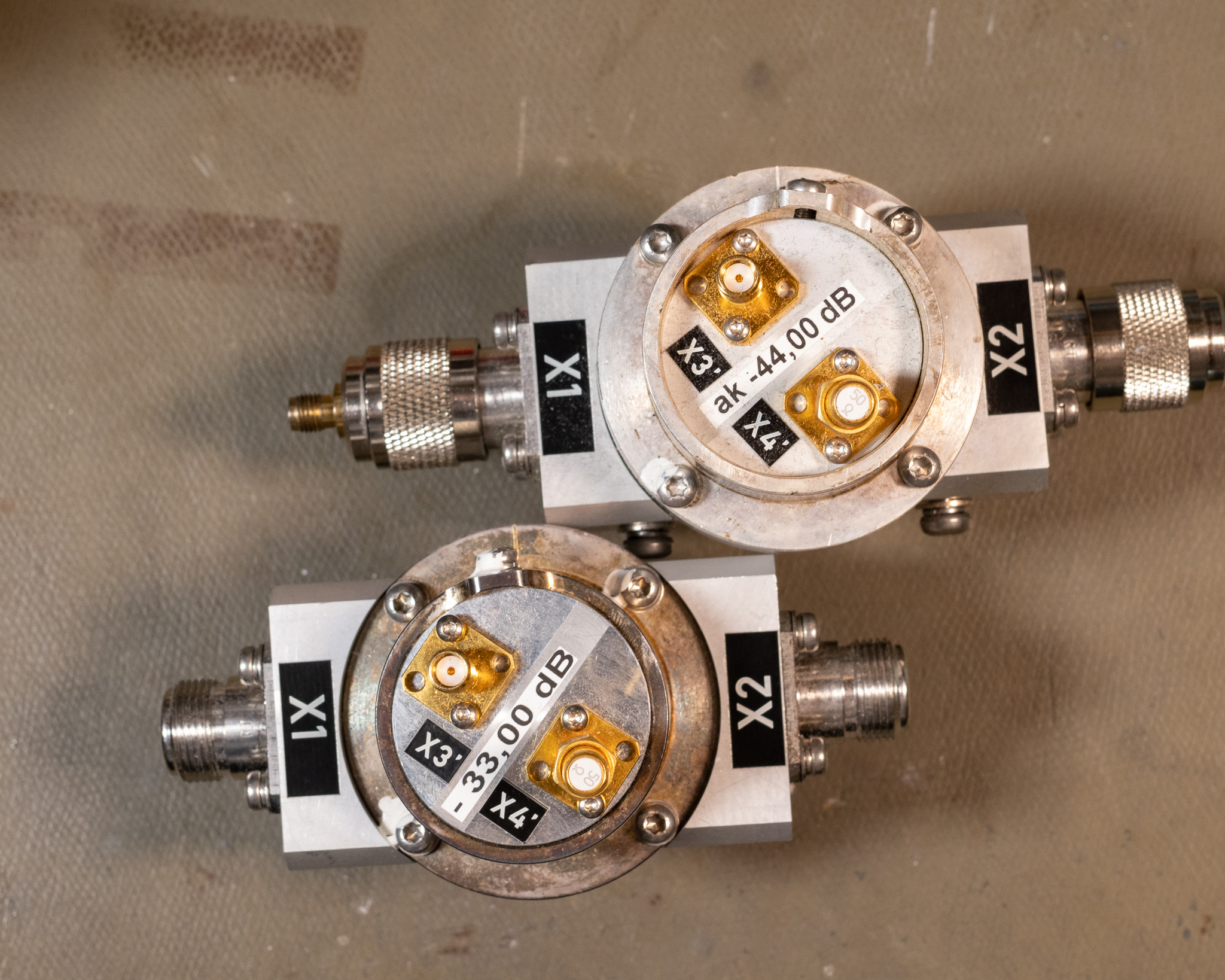
Above is the top view of the two devices I have, one is a -44 dB coupler, the other is -33 dB.
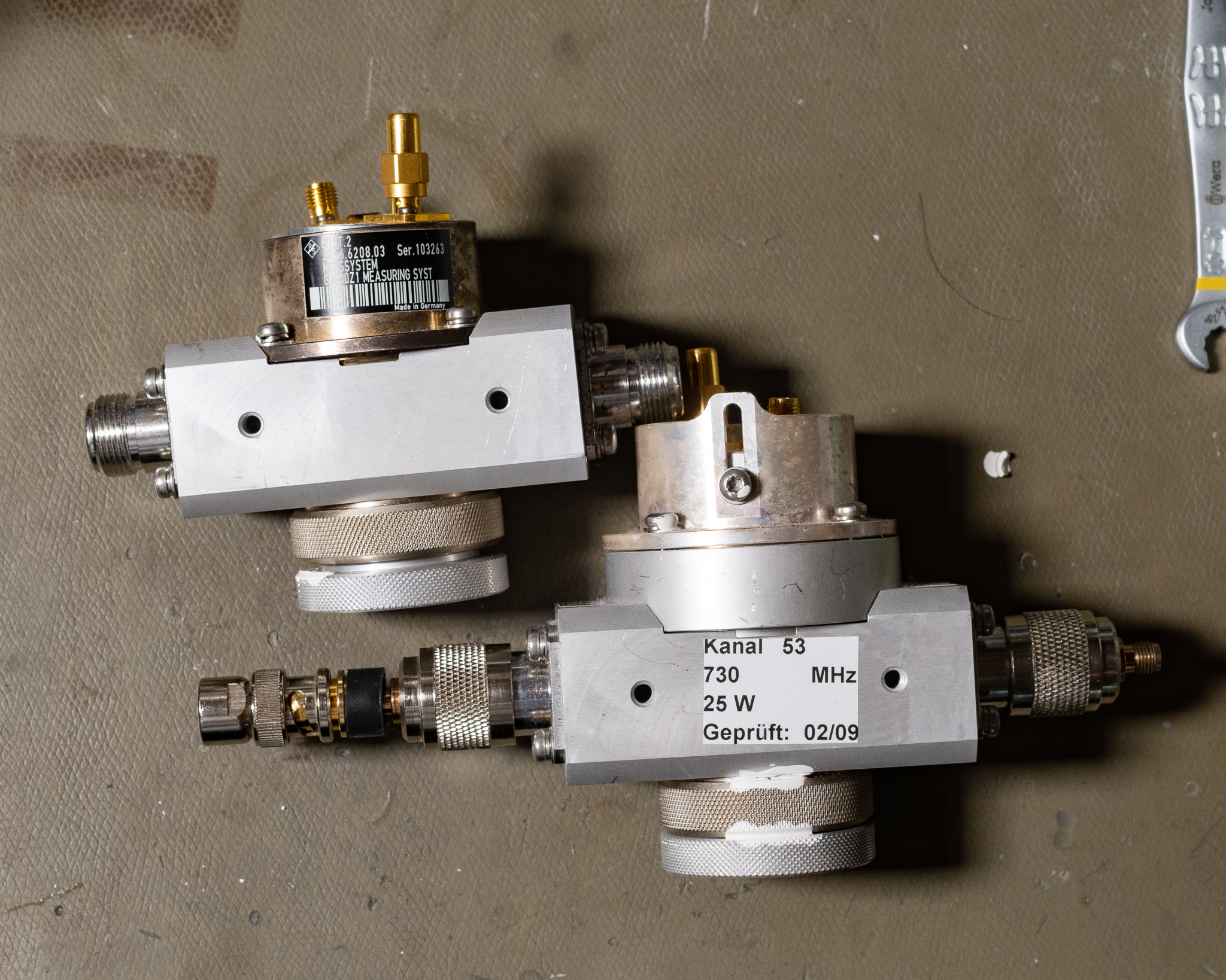
There is a very obvious tuning slug on the bottom, it's a large aluminium plug with a locking ring. The chassis looks to be aluminium with some type of high conductivity surface treatment.
As expected, the two SMAs correspond to two directions of coupling. Fine tuning of coupling is accomplished by loosening the Torx head screw near the piece with the SMA connectors, this lets the entire coupler slide up and down, giving a few dB of adjustment.
You may notice that the -44 dB coupler has an extra ring between the main unit and the coupler, presumably removing this ring will increase the coupling.
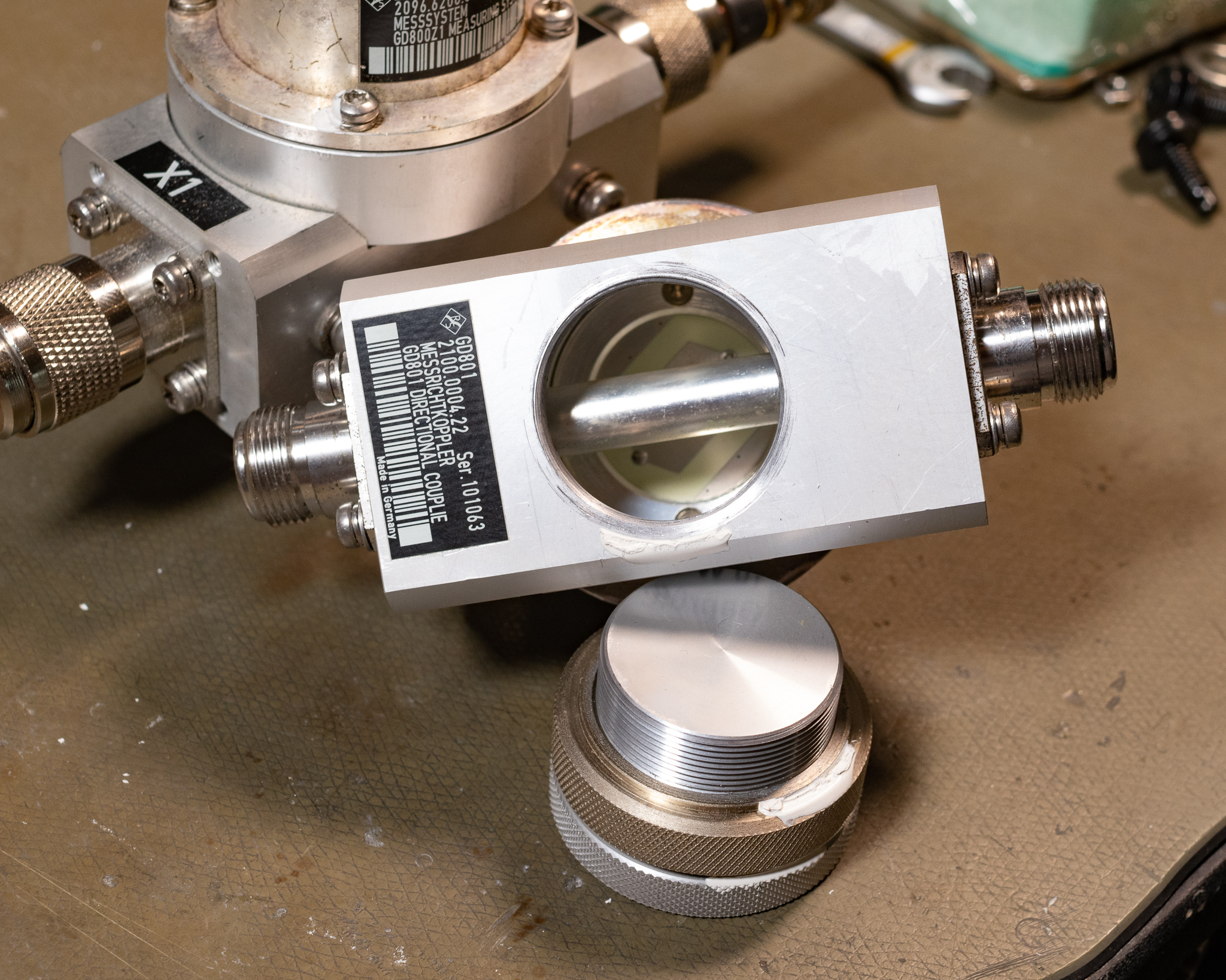
Pulling the plug on the bottom reveals a construction very similar to a Bird 43 meter, with a big air-dielectric coax.
Tuning the big plug does not seem to affect the coupling factor, but I did note that it seemed to affect the S11 measurement on the N connectors, and I measured around 40-50 dB return loss over a ~20 MHz bandwidth. I suppose this might also affect the directivity, didn't check that.
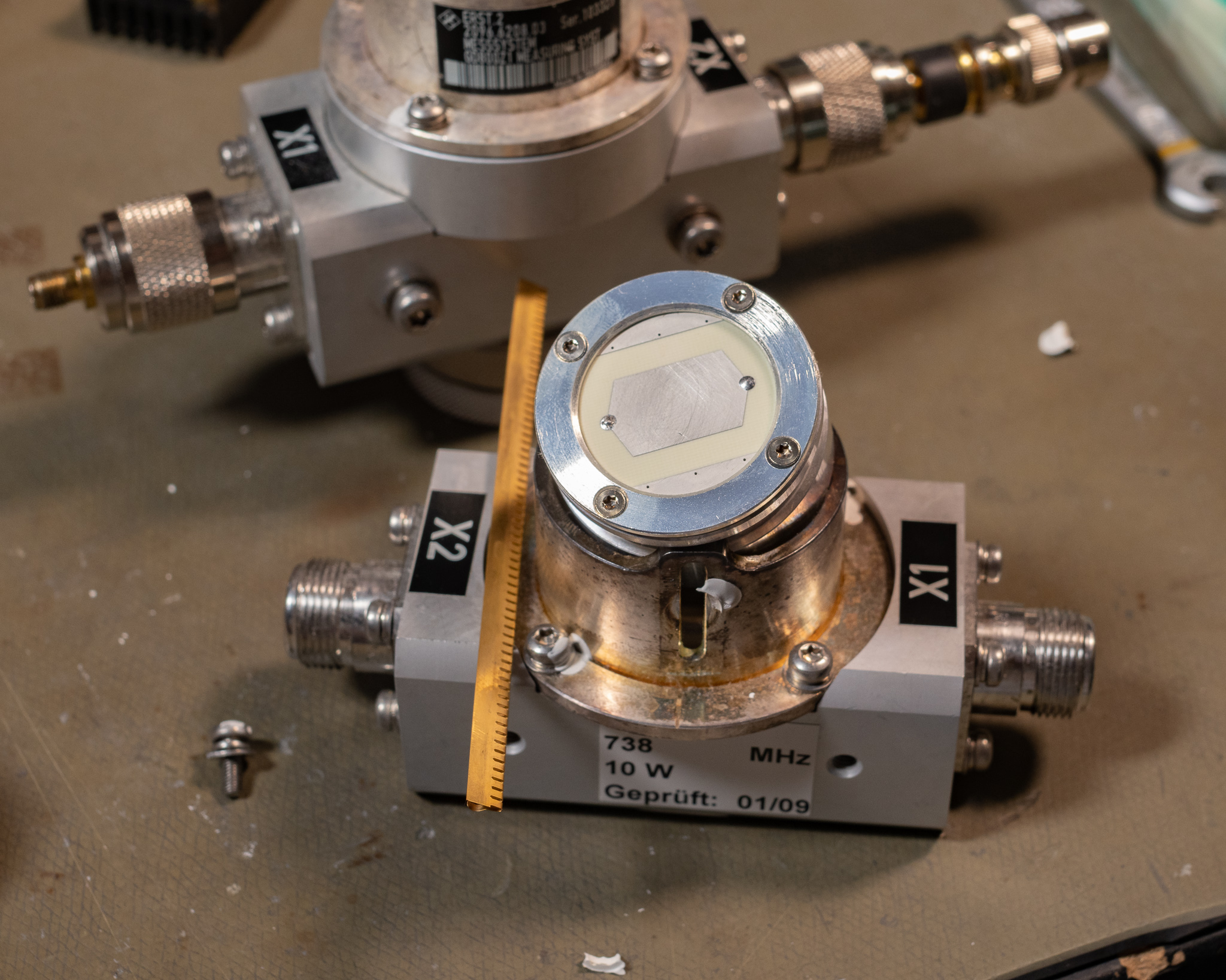
Popping the coupler itself out was easily done by removing the screw, a copper EMI gasket also came loose. We can see that this coupler design is basically a Bird type.
It seemed to be fine up to at least 1 GHz, and it still gave decent performance down to around 400 MHz, and by tuning the slug I was able to get the S11 measurement down to around -40 to -50 dB. This makes it practical to use for e.g. a 70 cm ham radio transmitter. If you pull the terminating SMA it basically becomes a non-directional sampler.
I'm not sure why these are marked for such low power levels; it seems that the coax piece itself could easily hundreds of Watts. It might be marked as such to match a specific transmitter system.