The 8802A Transmitter
The 8802A transmitter is a 50W continuous 450 MHz modulator, exciter and PA with good performance.
I've only documented the parts I decided to keep using in this entry, specifically the PA and the output filter.
In addition to these parts, the following PCAs were originally part of the unit:
- PLL/Modulator
This board was very similar to the receiver LO board, but operates at ¼ of the output frequency instead of 21.4 MHz offset. Modulation was direct FM.
- Exciter/Power/AF board
This board is similar in scope to the AF board in the receiver; it contained the final output doublers, pre-filtering and a 10 W PA module. For the AF stuff it had a transformer and several active filters; I didn't look very closely at these since my goal at the time was getting DV to work.
This board also provided the 8V power supply to the rest of the chassis.
- Remote Control Board
Probably the same board as the receiver, just controls the frequency selection.
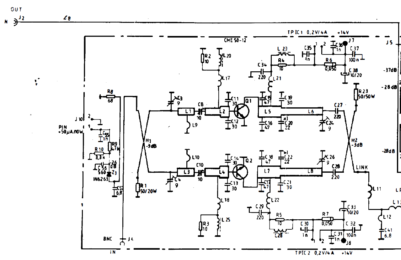
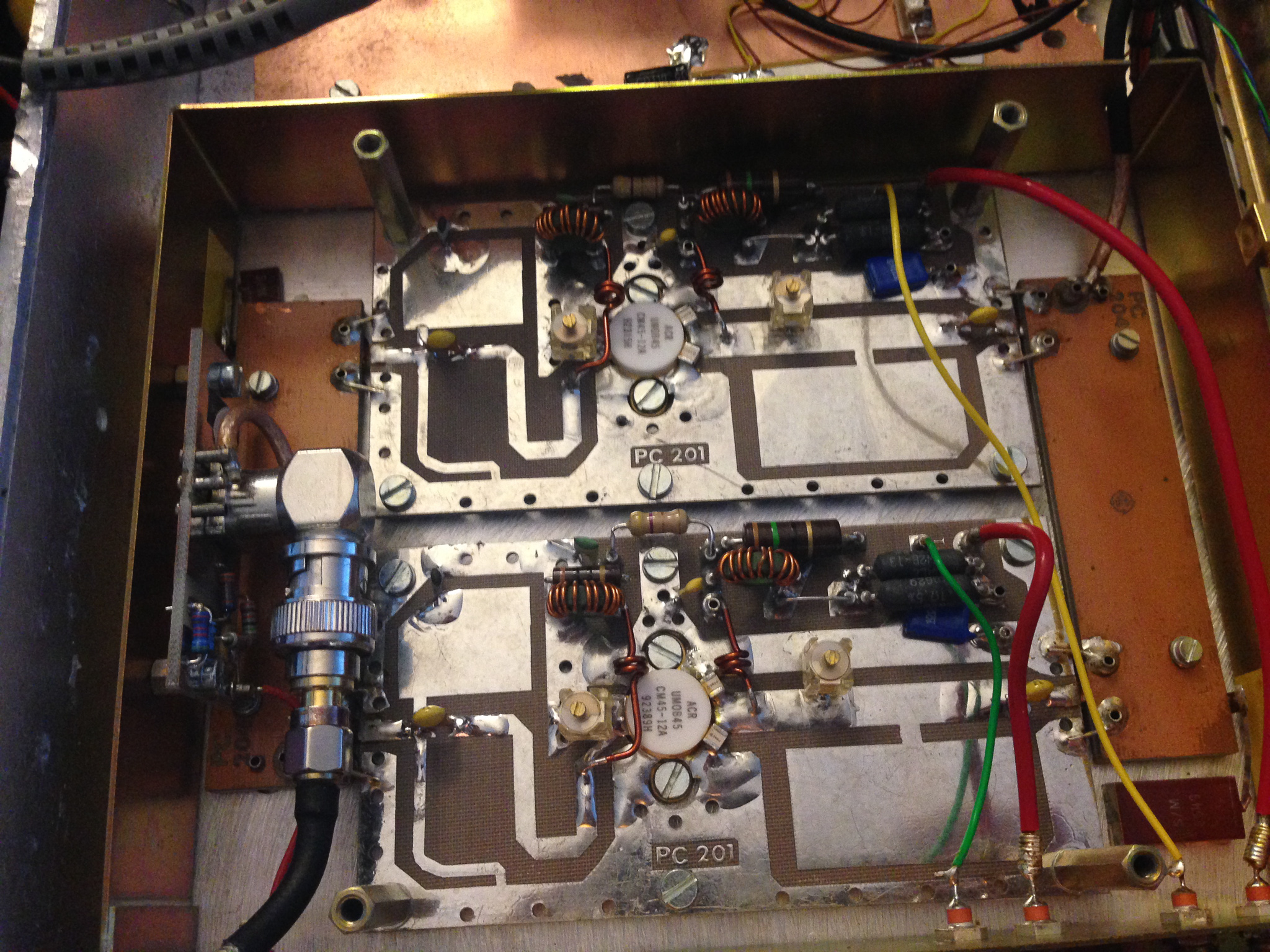
Power Amplifier Modules
The PA in this unit is implemented using four sub-assemblies as well as the harmonic filter.
Two identical PA modules are used, along with two quadrature couplers, forming a quadrature-coupled amplifier.
A couple of advantages are inherent to this type of amplifier:
- Good input and output impedance matching guaranteed
- High output mismatch tolerance
- Reduced power dissipation per transistor
- Some degree of redundancy
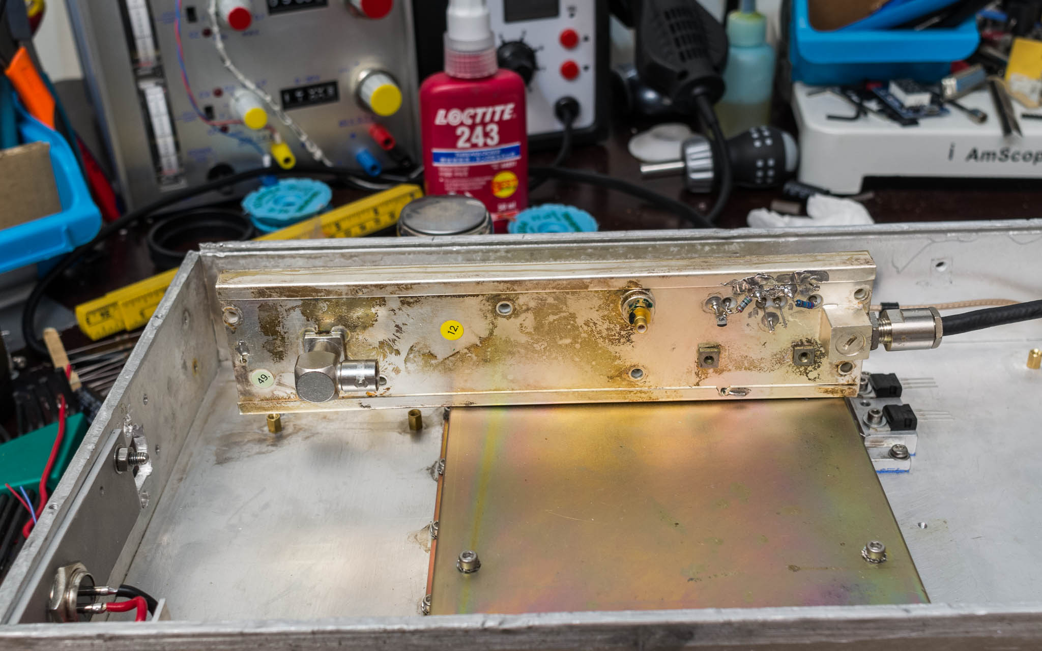
The entire assembly is enclosed inside a shielded box inside the main shielded box, presumably to avoid excessive RF leakage interfering with the control logic. Power and monitoring signals are fed through feed-through capacitors, while the coaxes go through notches in the enclosure.
The nominal input power to the PAs is 10 W, with approximately 50 W output power. A power detector is included on the input side, the output detector is part of the harmonic filter.
Each PA is a separate board, and the couplers are hybrid PCB based, Magnetic AB used this coupler design for several other PAs too.
The PAs operate in class C mode, running directly off a 14 V power supply, separate current shunts are included to aid in alignment and troubleshooting.
The big advantage for a PA of this type is that any return power from the antenna (mismatch) will primarily be dumped into R23, which is a 50 Ω 50 W stud mounted resistor. This means the PAs can tolerate more or less completely open or shorted antennas without any issue, though obviously the total power dissipation will be a bit higher.
According to the schematic title this PA is designed for operation from 400-470 MHz, and retuning is not particularly troublesome (in fact it works pretty well without any realignment). Alignment is done by applying a fixed input power and tuning the various trimmer capacitors on the two PAs to give the highest output power. It’s usually better to do input matching first, then output for both of the PAs. Checking input/output return loss is usually not required due to the quadrature coupled design.
A plastic trimmer tool is mandatory, and I advise against touching anything while the PA is active to avoid RF burns.
Alternately in a closed loop system alignment can be done by regulating a power level and monitoring the gain control level.
The input to the PA system is a standard BNC connector, so if the exciter portion isn’t operational then it can also be aligned by applying an external RF signal up to 10 W. The PAs are hard-wired to the power input and so as long as power+RF is applied they are active.
As mentioned above this design is not redundant, the most likely failure is a shorted RF transistor, since there is no separate fusing of the two PAs a single fault will disable the transmitter.
The schematic below is a different version of the PA, which is built as a fully integrated assembly with both transistors, couplers, and low pass filter all on one board. The Scandinavian version had all these as separate boards, but the general function and implementation of the circuitry is still pretty similar.
One of my units had a broken output termination resistor (split in half during transport, most likely). Keep in mind both the transistors and resistors contain beryllium oxide if this happens.
I replaced the broken unit with an Anaren G150N50W4B flange mount 150 W resistor instead; after removing the old resistor (held in with a nut from the heat sink side), two new holes were drilled and tapped and the new resistor screwed in. A piece of copper tape was cut to make a good and slightly flexible connection to the coupler output.
The Anaren resistor is highly affordable and available as of 2017 (check eBay, a number of Chinese sellers have used ones in stock). Keep mind that that model resistor should be installed with the flange solidly grounded to the chassis, I decided not to use any heat sinking compound for this reason.
These PAs could be suitable for linear operation if paired with a suitable bias regulator.
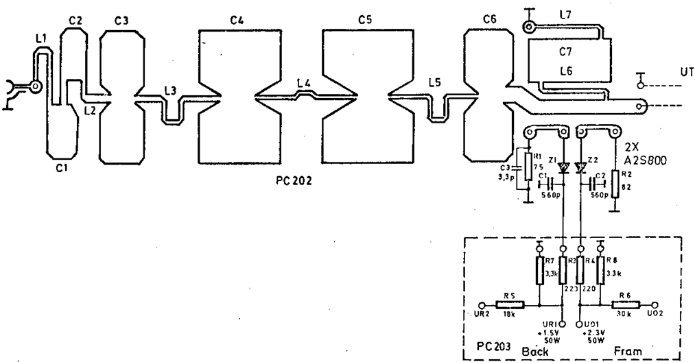
Harmonic Filter/Output Coupler
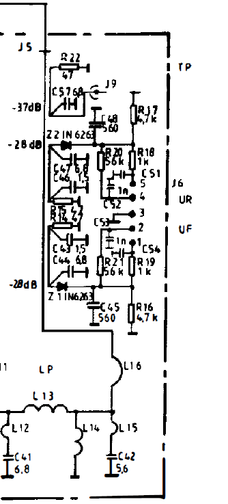
The harmonic filter/output coupler is a large PCB based filter assembly with a couple of couplers built in to provide some feedback.
The main PCB is sandwiched between two aluminium oxide plates, which are then covered by two silver plated copper outer plates providing the ground plane, a U-profile covers the ends.
With this filter the main PAs are able to produce around 50 W of quite pure RF. The filters have a notch starting around 800 MHz, with good attenuation up to approximately 2 GHz.
The coupler portion includes a –37 dB port routed to an SMB connector and further to a front panel BNC connector for testing, and two 3-port couplers which together implement a 4 port coupler providing forward and reverse power. A small PCB is mounted on the filter assembly which contains rectifier diodes.
It can be seen below that the primary circuit topology is a notch, rather than a pure low pass.
The picture below is from the TU8062 UHF power amplifier (likely used for manual UHF telephony), I believe it’s similar to the design of the NMT variant. The component values mounted on the coupler outputs are a match for my version.