A Simple 3D Printed Mounting Solution for Lucent RFTG-u GPS Receiver
I've designed a 3D printable solution for rack mounting Lucent RFTG-u receivers on cheap 2U shelves.
If you're like me you probably have a couple of GPS time receivers sitting around to ensure all your clocks tick at the same time.
Even if you're not like me a GPS time receiver is a basic part of any modern home, and the Lucent RFTG-u set was available through most of 2014-2016 at very low cost from eBay.
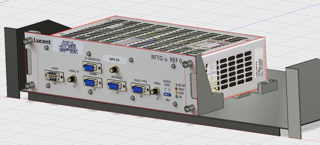
These units are pretty reliable and look pretty nice, they were OEMed by Symmetricom/HP and the units on eBay were new-in-box spares. I bought one set originally, then later ordered 4 Ref 0 units that don't have an internal GPS and modified two of those to Ref-1 units to make 3 full sets (1 in use, two as cold spares).
They're 10" rack mount jobs, and very annoying to install in a 19" rack.
The Solution
My solution involved using 2U rack shelves that are readily available at very low cost from many distributors, they're normally made of painted bent sheet metal and often come with some vent holes.
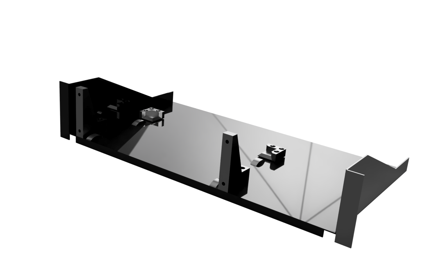
To mount the RFTG to the shelf, I made 3 different 3D printed pieces that are used to support the unit slightly suspended above the shelf bottom. The basic layout is rendered poorly here:
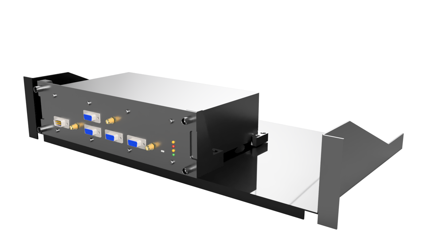
Here's another poorly rendered view with the RFTG modelled in:
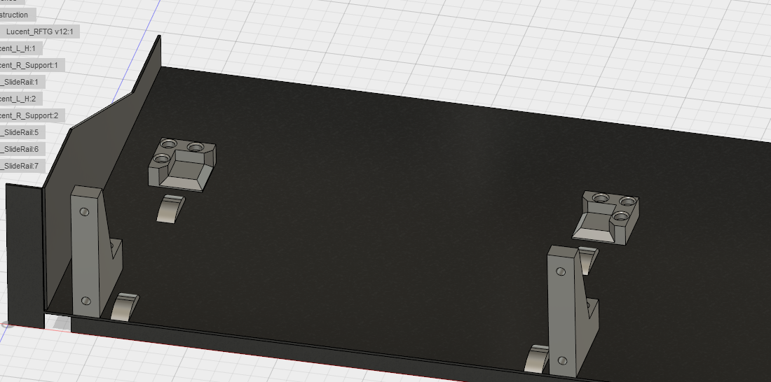
The basic pieces are a modified L bracket with two M4 inserts that line up with the mounting screws on the RFTG, to provide additional support and simplify mounting a rear corner piece is installed at the back.
The L bracket has two M6 inserts in the bottom to attach them to the plate, the rear support has three 4mm free holes for installation. These are sized to fit a DIN912 M4 screw with a nut on the bottom of the plate.
Finally, in order to simplify installation I included some slider-pieces that are glued to the plate to line up with the bottom edges of the RFTG to make it easier to slide in and out and keep it from dropping when the mounting screws are loosened. These pieces will sit below the bottom of the RFTG when installed.
Installation
The parts can be downloaded off Thingiverse: https://www.thingiverse.com/thing:2726667
Printing these in black PLA they look great and provide adequate strength, the RFTG can easily be installed into the support while the shelf is racked.
For installation the M4 and M6 inserts need to be heat-pressed into the L brackets, these can then be installed on the RFTG and aligned. The rear M6 hole is open and a transfer punch can be used to line up the first position. After drilling the second L bracket can be installed the same way.
After that, the other set of M6 holes can be measured out using an angle as they are 24mm nearer the edge from the first.
The rear supports can be installed using Loctite 401/any cyanoacrylate super glue, this is probably adequate but I was able to drill through the holes after gluing to get some M4 screws+nuts through.
At this point the slide supports can be super glued in place, be careful using Loctite 401 since they're basically impossible to remove unless you use a tiny amount of glue. Align them so they slide on the solid metal parts of the unit near the sides for a smoother installation. I recommend using at least 4 pieces for best support.
Metrics
A note on my use of metric screws here: the RFTG comes with imperial threads; I modified all my units by removing the original captive screws, drilling out the center to 4.2 mm and drilling the support stud up to 7 mm inner diameter to seat a standard DIN 912 M4 screw.
I primarily did this since I didn't have any taps suitable for the original threads and had previously made some ugly aluminium brackets for this purpose. Another reason was my dislike of Philips head screws, as I strongly prefer Hex or Torx heads for all my own gear.
If you're so inclined you could probably find roughly equivalent imperial threaded inserts and use those instead. The insert hole dimensions are 5 mm nominal for the M4 holes and 8 mm nominal for the M6 holes.
If you decide to also drill up to M4, the top hole has enough clearance for a M4x16 mm screw.