HP Z420 (& Z620) Motherboard Wiring

This is a collection of what is required to put a HP Z420 and (probably) Z620 motherboard in a new case.
The Z420 is a pretty decent machine, I use one daily as my workstation. After upgrading the processor in my main machine to a E5-2697v2 12 core I had a spare E5-1650v0 6 core CPU, so I decided to buy a used Z420 motherboard and use it in a new 4U server chassis.
The benefit of a system like this for me is the large amount of PCIe slots available, meaning upgrades are very practical. It also supports up to 64 GB of registered ECC DDR3 memory, which is a good amount for a file server + some other VMs.
Note that 64 GB of RAM is the official maximum with 8⨉8 GB of RDIMM's, but success has been reported with fitting up to 8⨉32 GB LRDIMM's for a total of 256 GB of RAM.
Note that systems with a boot block date from 2013 can boot second generation (v2) Xeons, but older models with a 2012 boot block are not capable of this without some tricky modding. The boot block is listed under "System Information" in the BIOS.
Note also: when using the on-board SATA: there are two 6 Gbit/s ports (dark grey, near the edge of the board), the remaining ones are 3 Gbit/s. See the manual for the location of these, but use the 6 GBit/s for SSDs when possible.
Note also also: these boards can't do NVMe boot (unless you have a AHCI compatibility mode SSD), I flashed Clover onto a small USB thumb drive and hooked it up to one of the internal USB 2.0 headers and boot off that.
Note also also also: The motherboard does not support PCIe bifurcation, if you want multiple NVMe drives on a single PCIe slot you need to get a ~$200 PCIe 16x to 4xM.2 adapter. The reason for the cost is that an active PCIe switch is required to convert from 16x to 4x4.
Chassis
I decided to buy a Inter-Tech IPC 4408 4U chassis with 8 hot-swap bays. The motherboard fits fine except two missing screw holes near the center of the board. I simply left these out, but the easy fix is to screw a spacer into the motherboard with a nut+washer and some vibration damping tape to support it without drilling new holes in the case.
Don't bother with the included rear 80 mm fans, they move a lot of air very loudly, and some Noctua 80mm's move a lot of air quietly instead.
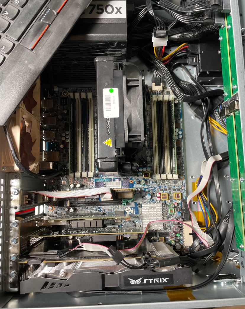
Above we see the benefit of a workstation/server grade board, it can fit a radio clock board, a 10 Gbit network card, a LSI SAS controller, and a graphics card and it still has one 16x slot available.
At the time of writing I have some additional RAM and SAS cables in the mail.
Above we can also note one annoyance, all the front panel I/O is right by the optimal location for the graphics card (in terms of slot utilization, not for thermals!). Some careful cable management is required when installing the GPU in the bottom slot.
A note on the front fans on the IPC 4408 chassis: there are holes drilled for up to 4x80 mm fans on the front, but they have non-standard screws. These fan locations are not mentioned in the chassis documentation, and I can see why since they're nearly impossible to get to.
I stuck the front intake fan on with VHB tape to get it done without dismantling the entire front drive cage.
The motherboard has a non-standard (single) serial port header next to the rear audio jacks. The cable seems to be P/N 628646-001 or 611901-001. Note that it's not just a cable, it seems to contain at a minimum a level shifter IC, maybe more.
Buttons & LEDs
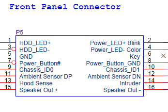
The picture above shows the wiring for the power switch, lights etc. pin header. Note the location of the Key pin. There is no RESET button on this model. Note that the speaker can be plugged into this connector, or to a smaller 2-pin connector near the SATA connectors.
I found a 16 pin 0.1" header block and re-wired the front panel ribbon cable into this to make it easier to install and remove. To implement the key, just fill a blank pin with solder and install it to block that hole.
No connection is required for pins 9, 10, 13, and 14.
For the ambient sensor, connect pin 11 to the collector and base of a 2N3904 or equivalent NPN transistor. Connect pin 12 to the emitter. This is used to control the chassis fan speeds and it may run at full speed if no sensor is connected.
I think there's some dual colour stuff going on with the power LED, but standard wiring seems to work.
Power
To power the computer using a normal ATX power supply, buy an adapter on eBay, this adapter seems to re-wire some pins, and change the 5 V standby to an 11 V standby voltage with a little boost converter.
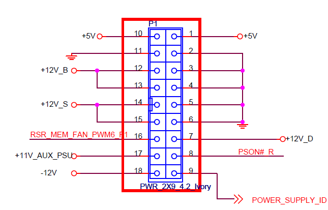
I found the above diagram from HP, but it's not very important if you just buy a pre-made adapter.
The motherboard also requires an 8 pin 12 V CPU power plug, the wiring is standard ATX.
I used a Corsair RM750x, though a lower wattage supply is fine (HP uses a ~450 W supply AFAIK).
I have later been informed that a ~650 W supply was also fitted in some units.
A fully modular supply is not required but is very convenient to work with.
Fans & CPU Cooler
I bought a used closed loop HP water cooler, so this was plug and play for me. The connector is a 5 pin variant of a standard fan header; it's a normal 12 V, tachometer, and PWM header. The 5th pin is grounded when the high power cooler (i.e. water cooler) is installed.
To get rid of alarms, you need to plug in the following fans with a minimum of a 3-wire connection (i.e. with tachometer):
- Memory fan (may be a rectangular molex plug, or a standard 4 pin fan)
- Rear chassis fan
- Front intake fan
The HP fan connectors do not use standard key locations on the plastic, but the wiring is standard, and I just forced standard 4-wire fan plugs into them without any issues.
A reader has informed me that especially for fully kitted memory configurations, an actual memory fan may be necessary to avoid overheating and associated bit errors, in particular for the front-side banks.
Rear I/O Plate
No official rear I/O plate exists, the holes are part of the original chassis. There are some unofficial Z420 and Z620 I/O plates on eBay, the one I got required some Dremel™ work to expand the audio jack holes to make it fit.
I used a diamond grinding wheel for this work.
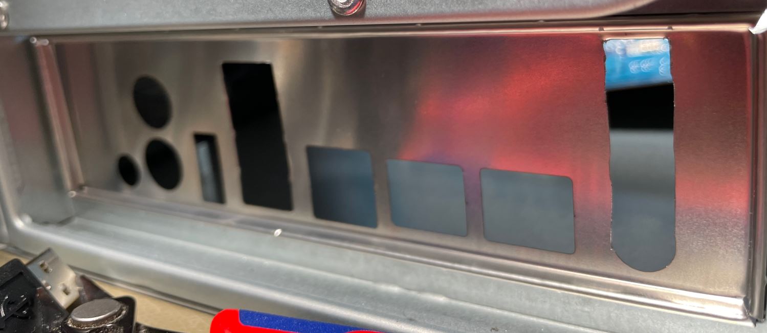
Otherwise it's fine. The Z620 has dual Ethernet so there's an unused cutout when used with a Z420 board.
USB, Audio, FireWire Plugs
My chassis has a standard USB 3.0 plug, and no USB 2.0. The motherboard checks for cable sense lines for the front panel USB 2.0, USB 3.0, Audio, and FireWire plugs.
It also checks for all required fans, and if any are not present then the user will be prompted to press F1 to continue startup.
The USB 2.0, Audio, and FireWire can be bypassed with standard jumpers, see pictures below:
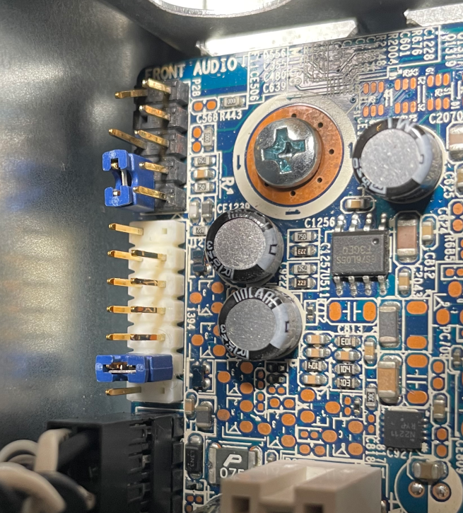
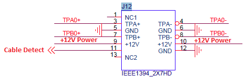
The FireWire was the hardest one to figure out, but I found this diagram of the connector from an earlier model:
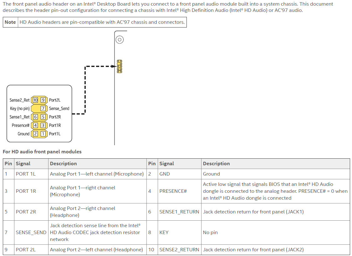
The front audio is a standard pinout as far as I can see:
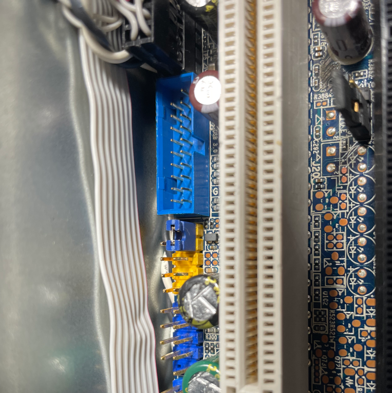
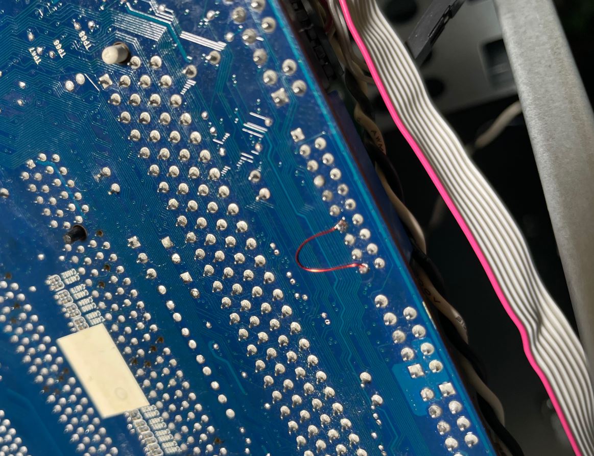
The USB 3.0 requires soldering, or re-wiring of the cable connector (mine is molded on so I had to solder):
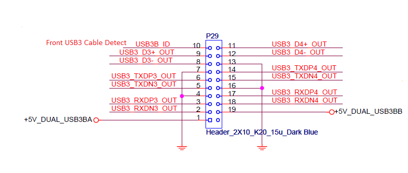
Connect pin 10 to pin 7 on the underside of the motherboard to defeat the cable sense.
What Do Memory Errors Look Like?
This is an ECC system – you'd expect it to correct errors right? I don't know if Windows exposes memory errors in any convenient way, the logging system probably has something for it (try digging around the folders in the Event Viewer some time).
On Linux turns out correctable errors look like this:
Feb 15 22:57:17 dl kernel: EDAC MC0: 1 CE memory scrubbing error on CPU_SrcID#0_Ha#0_Chan#1_DIMM#0 or CPU_SrcID#0_Ha#0_Chan#1_DIMM#1 (channel:1 page:0x9b7307 offset:0x0 grain:32 syndrome:0x0 - area:DRAM err_code:0008:00c1 socket:0 ha:0 channel_mask:2 rank:255 )Feb 17 03:22:54 dl kernel: EDAC MC0: 1 CE memory scrubbing error on CPU_SrcID#0_Ha#0_Chan#1_DIMM#0 or CPU_SrcID#0_Ha#0_Chan#1_DIMM#1 (channel:1 page:0x9b7307 offset:0x0 grain:32 syndrome:0x0 - area:DRAM err_code:0008:00c1 socket:0 ha:0 channel_mask:2 rank:255 )Feb 17 03:46:18 dl kernel: EDAC MC0: 1 CE memory scrubbing error on CPU_SrcID#0_Ha#0_Chan#1_DIMM#0 or CPU_SrcID#0_Ha#0_Chan#1_DIMM#1 (channel:1 page:0x9b7307 offset:0x0 grain:32 syndrome:0x0 - area:DRAM err_code:0008:00c1 socket:0 ha:0 channel_mask:2 rank:255 )
Here I've simply the system log for 'memory scrubbing error' using this simple command:
sudo journalctl -k -b all|grep "memory scrubbing"
You can also pipe this into wc -l to get a count of errors for as long back as the system logs go – maybe useful for logging these things.
From what I've gathered I may have a slightly dodgy DIMM in the system, but the error rate is usually no more than 2 per day lasting a few days at most. Apparently this is quite a common occurrence on servers with ECC, to the point that the error rate I'm seeing here wouldn't even warrant replacement of the DIMM unless it got worse.
Without ECC this issue would have gone unnoticed until programs started crashing, so it goes to show this actually works.