
ITT Mackay Marine 3021N Receiver (Part 1)
The ITT Mackay Marine 3021N is a mid 70's communications receiver, designed for merchant marine and military use. I've basically built it again using modern electronics, which will be covered in detail in this series.
This is part 1, covering the basic overview of the receiver and its role in the original marine communications system. I acquired the 3021N some time the middle 2010's, and started serious work on it in 2018. The series has its own tag: 3021N
Table of Contents
Series Overview
This is part of a series covering the radio as it was built and used, and an overview of the various modifications I have made to the receiver. See tag 3021N for the rest of the series.
Receiver Overview
This stately 3U rack mount receiver covers 15 kHz to 30 MHz in 100 Hz steps, tuning is via an open frame optical encoder wheel, and the current frequency is displayed using a highly modern 7-segment display. Note that the documentation for the 3020A receiver is almost entirely the same, but the 3020A uses BCD thumb-wheels for frequency entry.
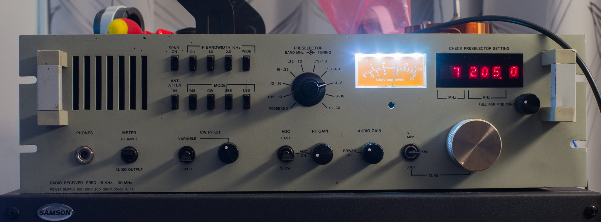
Receiver modes include: AM, CW (variable side-tone), USB, and LSB. It has crystal filters with bandwidths of 0.4, 1, 2, and 8 kHz usable in the AM/CW modes, and approximately 2.7 kHz SSB filters (separate filters for USB/LSB).
Note that the N suffix indicates the 6 kHz wide filter, some models may have 8 kHz filters.
The RF input is intended primarily for direct connection to relatively short whip antennas, and it has a sophisticated RF preselector box that acts as a selectable band pass filter, and to some extent also an antenna tuner. This also houses a selectable attenuator.
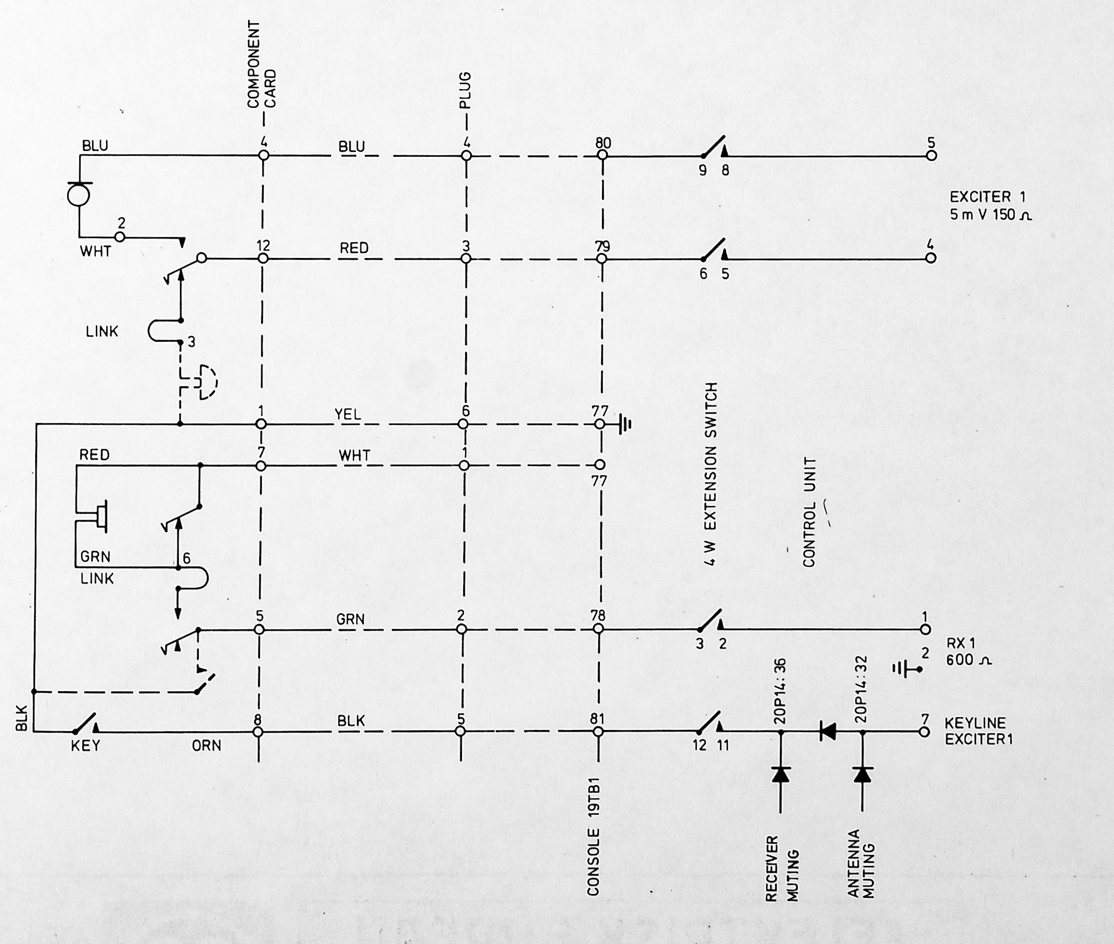
The rear panel also includes extra speaker outs, and my unit came with a transformer isolated 600 Ohm output which was likely connected to a ships internal telephony system. An external RF inhibit signal is also available to disable the receiver temporarily, this would likely be connected to the associated transmitter PTT signal. This input overrides the AGC system to minimum gain, and both mutes audio and ensures that the AGC system doesn't operate during transmissions.
All these systems would operate off ship power, but also had battery backups (usually 48 V). To power some equipment such as this receiver and the transmitter exciter an inverter (electronic/vibrator) would be used.
Intended System Use
This section uses documentation for the Elektrisk Bureau "Orion" system, which consisted of an EB built transmitter (usually EB 600 or EB 1500 MF/HF transmitters), as well as system components like the consoles and telephone exchanges. The receiver were typically off the shelf, including the 3021N.
Console
The 3021N would normally be part of a system consisting of at least one receiver and transmitter (usually two of each for redundancy), some kind of operators console, and wired into antennas and the ships intercom/telephony system.
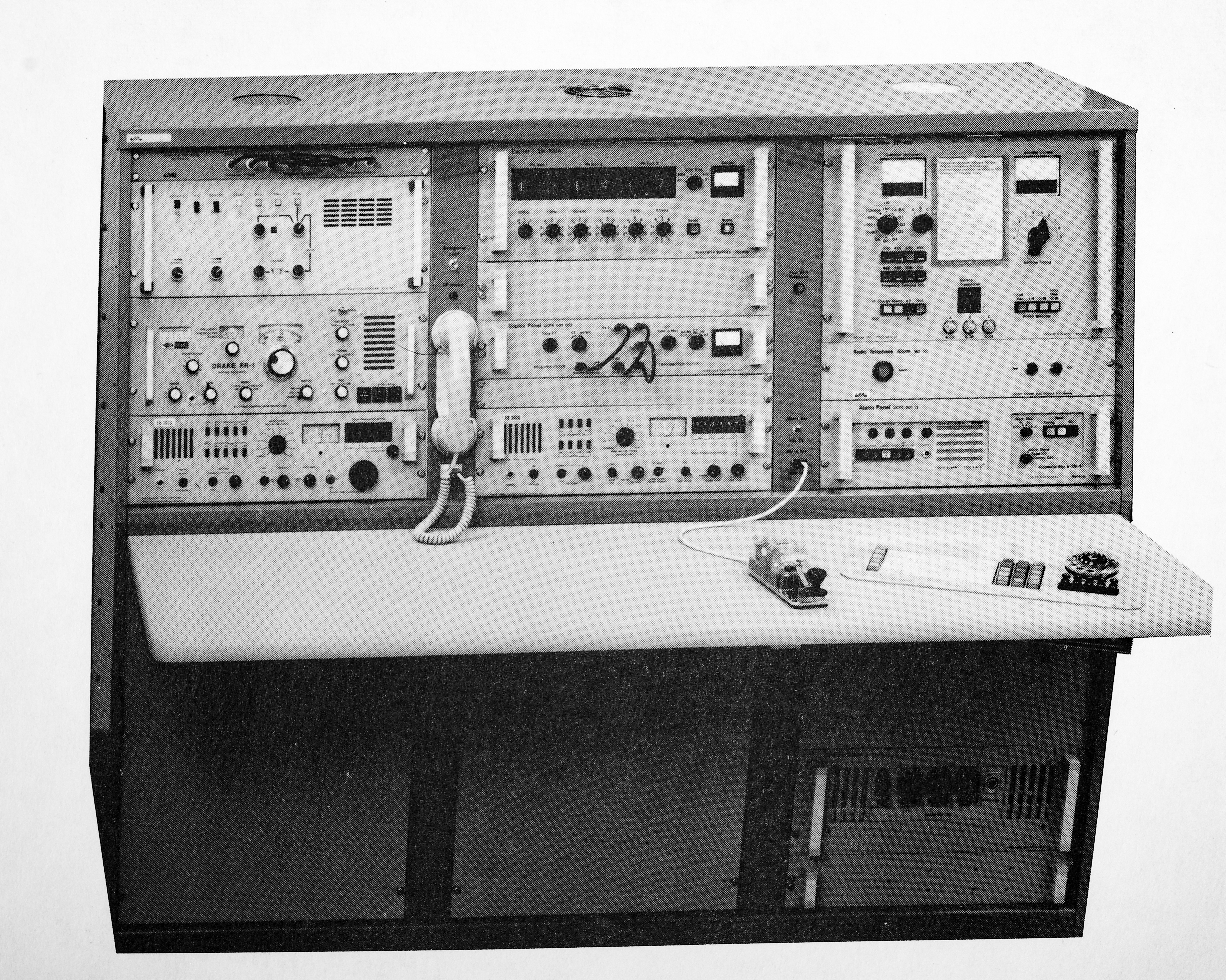
Above two 3021N receivers are shown as part of an EB Orion system operators console. The various other components include a patch panel (top left), possibly a receiver or transmitter controller (maybe an audio processor or scrambler), a Drake RR-1 LW-HF Receiver, and a 3021N.
Top middle is an EB Orion Exciter, which generates the HF signal (AM, SSB, CW, FSK), a blanking panel, a HF Duplex/filter unit for duplex telephony.
Top right is likely an EB 600 or 1500 remote control panel, middle is unknown but possibly some sort of alarm receiver of similar, bottom is a combination of an Auto Alarm receiver and an automatic distress keyer.
The bottom area is likely the power supply system (with 48 V batteries, charger, and mains input).
What appears to be missing is the VHF system, it looks like the pictured unit contains an integrated phone exchange to the right. There is obviously also a morse-key.
Transmitter Exciter
The Exciter is part of the EB Orion system, and would be paired with an entire rack full of transmitter and antenna matching system. A typical ship might have 2-4 of these.
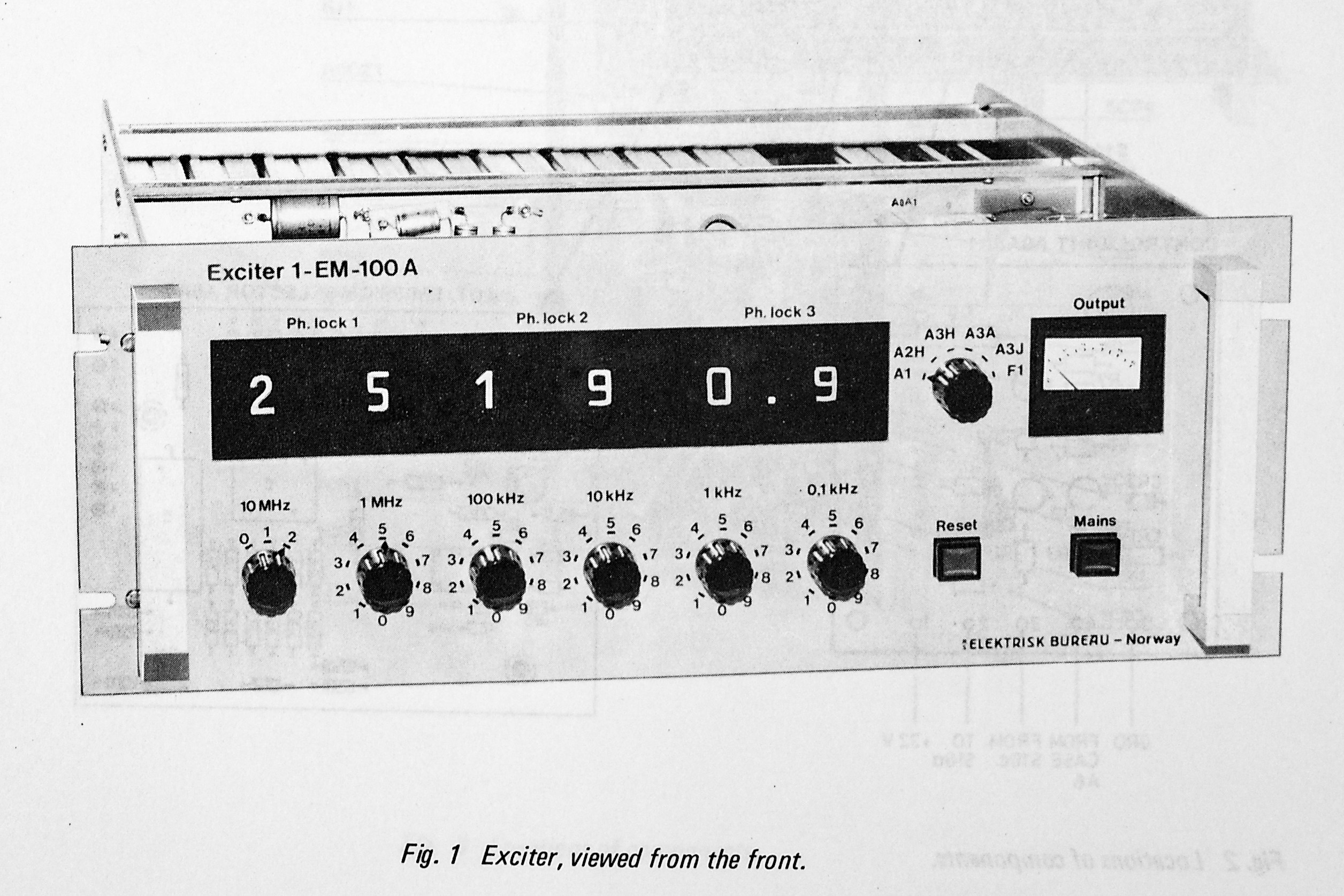
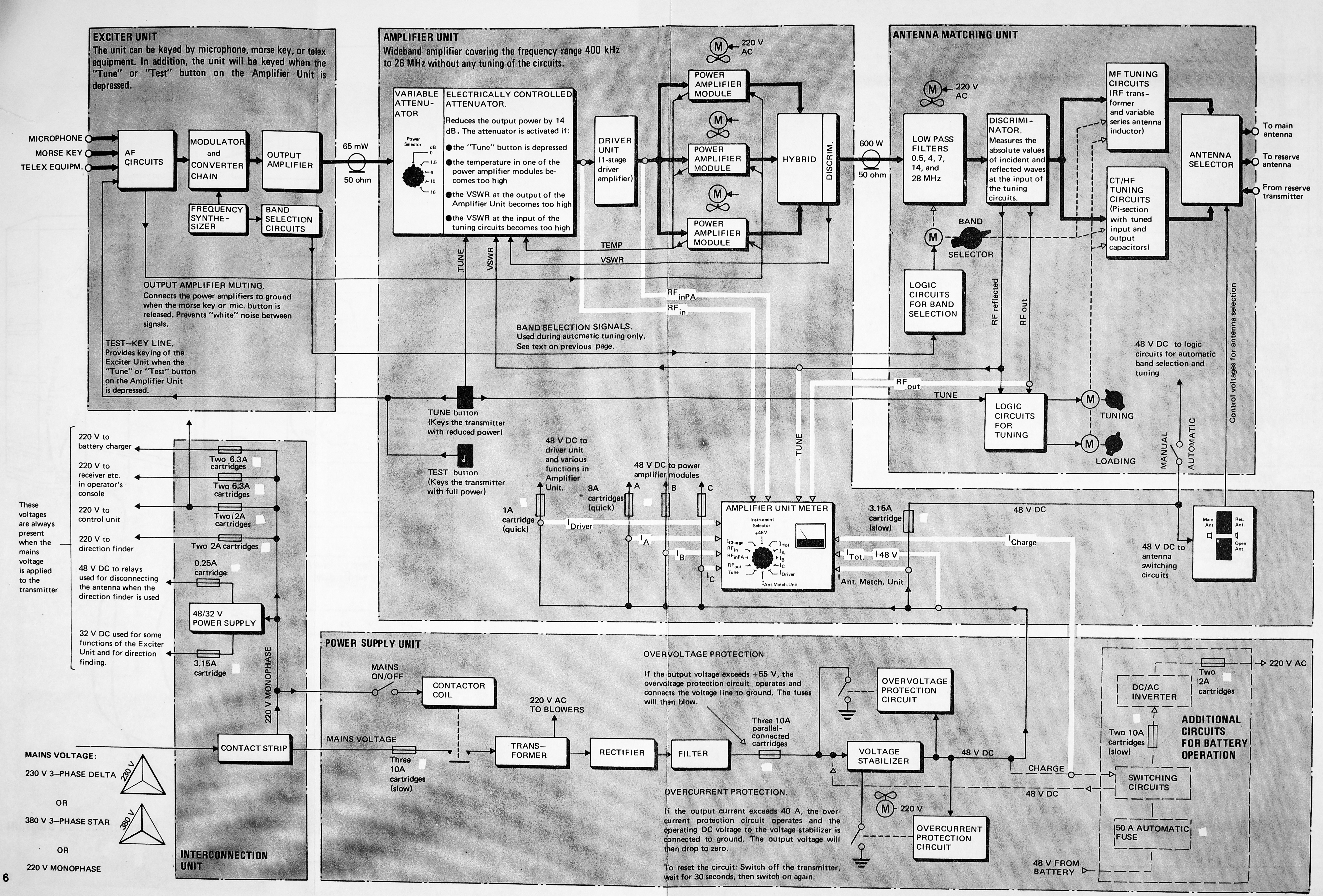
This Exciter can either be installed in the operators console or as part of the transmitter rack, but it requires 230 V AC instead of the 48 V DC that the transmitter takes. The details of the transmitter are out of scope really but the block diagram is shown below:
I know a remote-controlled variant of this device exists, with remote frequency and mode control.
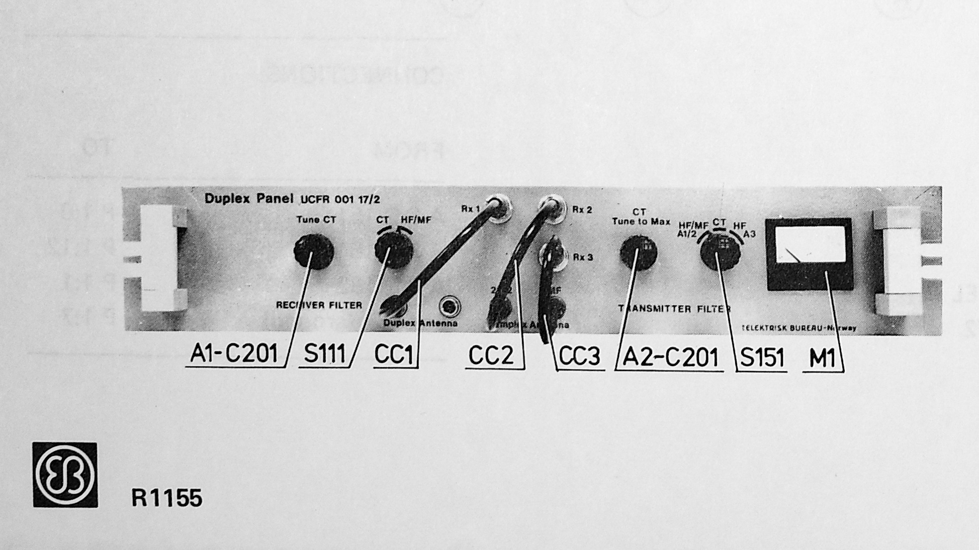
Duplex Panel
The Duplex Panel contains a couple of different filters and some tunable components to ensure sufficient isolation between a transmitter and receiver operating in the low HF bands. This duplex mode was used when telephone calls were made. It could also optionally contain some additional band pass filters.
Transmitter Control Panel
I don't have documentation on the exact panel used in the picture. It appears to be a remote control panel for an EB 600 or EB 1500 transmitter. This control panel duplicates the controls on the transmitter, which include various measurements of voltages, control of automatic tuning and test keying.
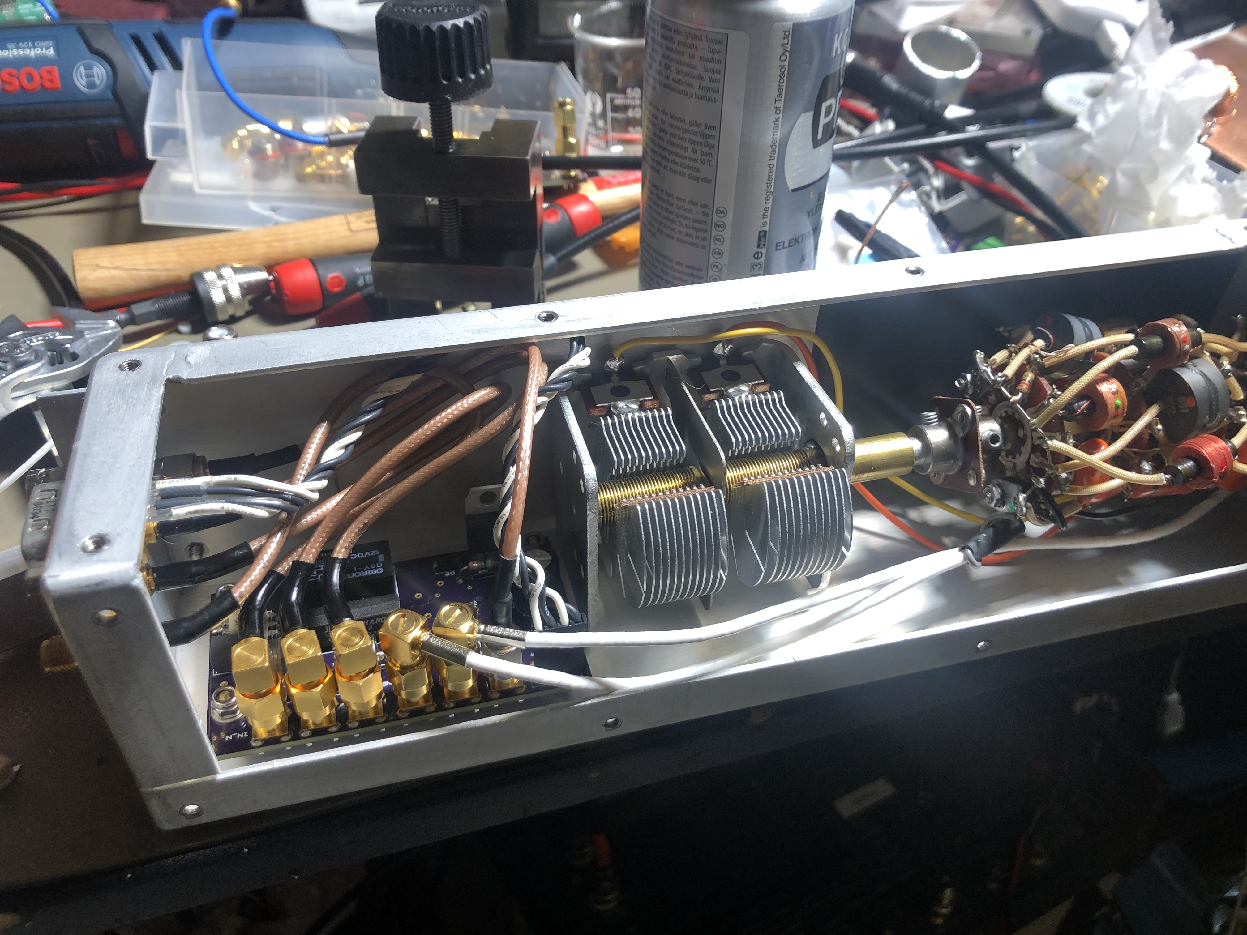
Note that in this system the automatic tuner must be pre-set for each band and various elements soldered/wired in or out of the circuit path through a ridiculous multi-deck rotary switch. This process takes around one day to match a new antenna, but after this the tuner will operate like a modern automatic one. The tuner is pictured below.
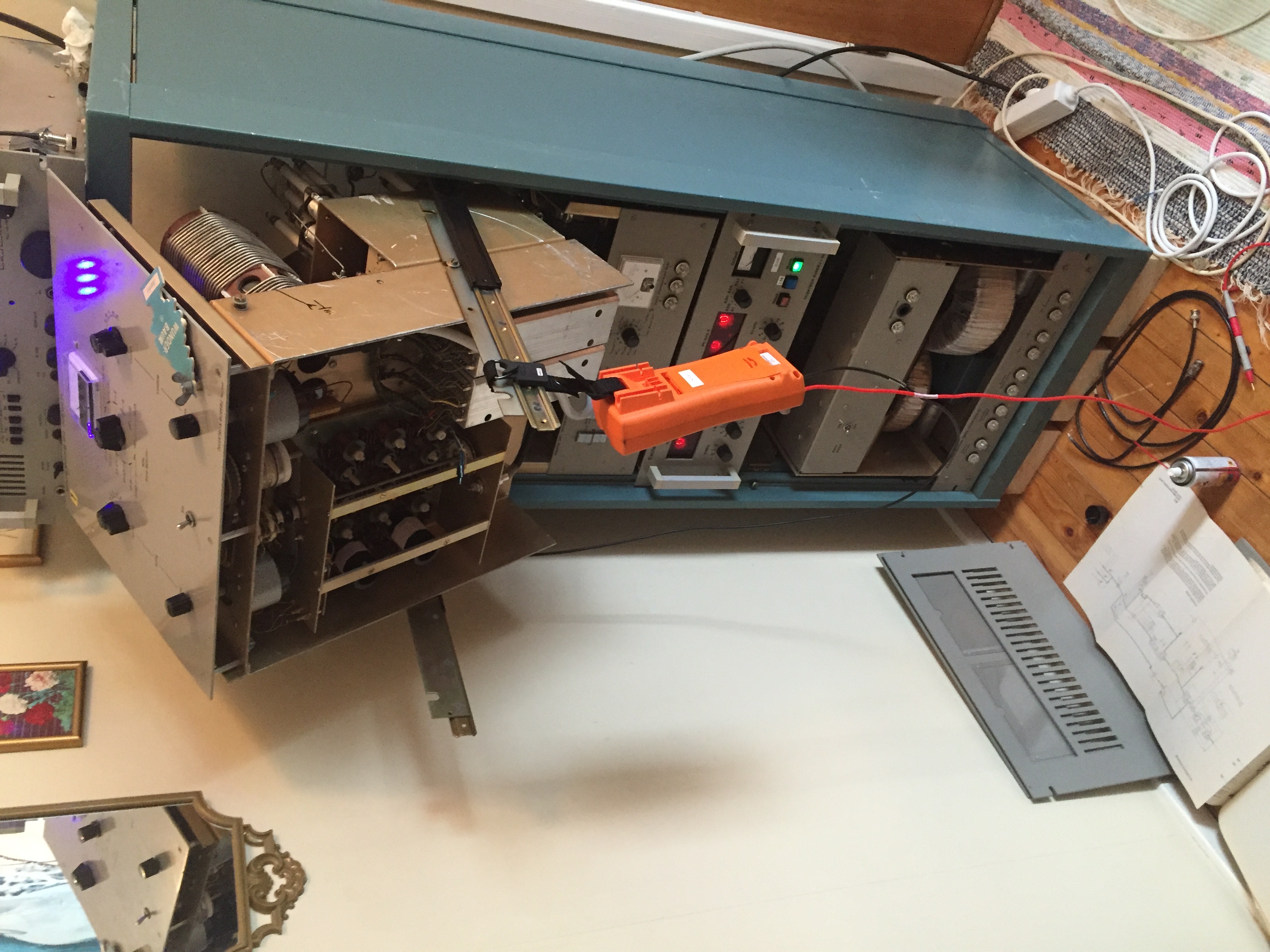
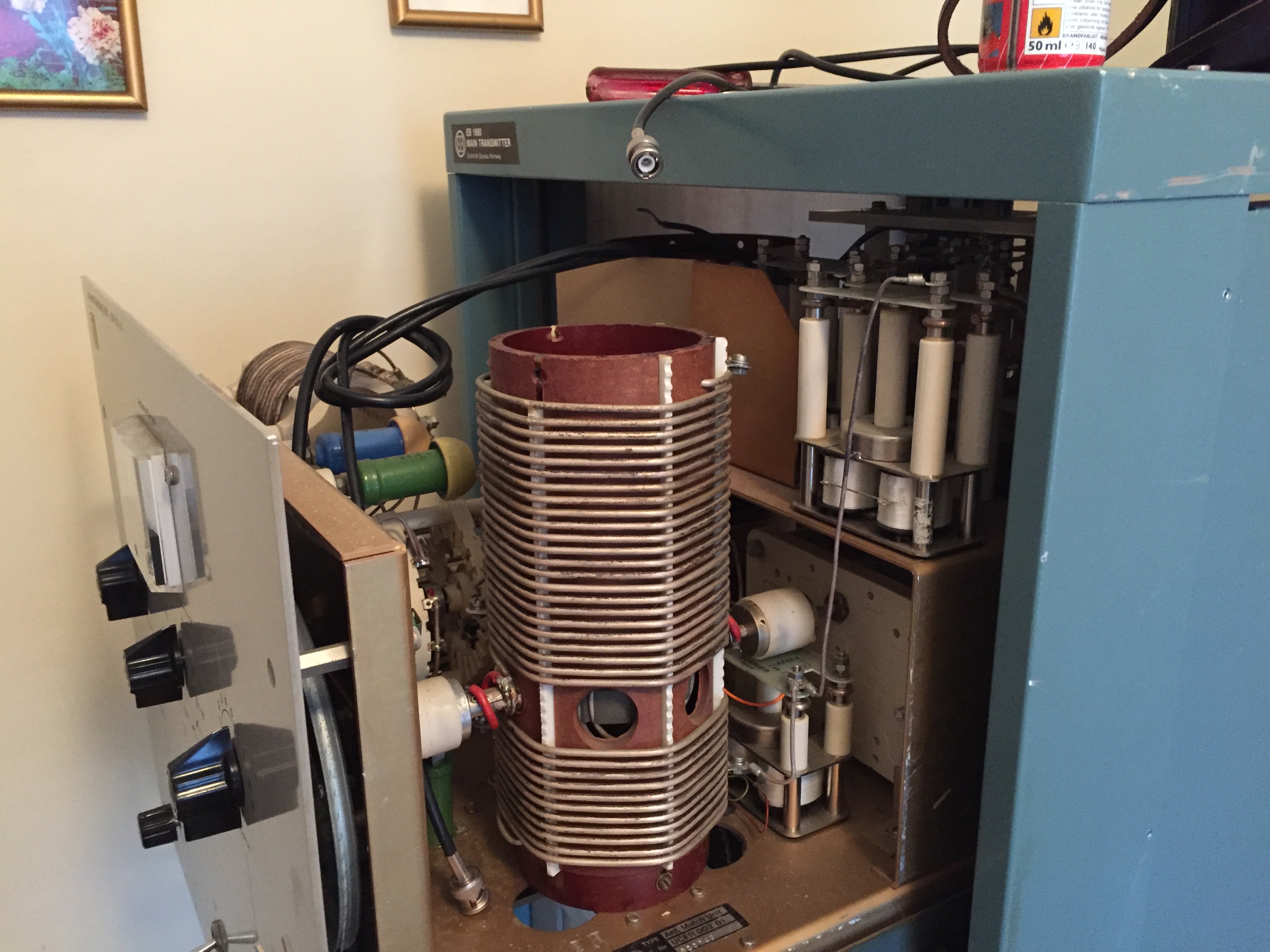
Above one of the variable transformers is shown, it consists of a vertical helix inductor, and a rotating winding-ball inside it adjusts the coupling to perform tuning. This tuner is suitable for operation at 500 kHz and across the MF/HF band around 1.7 to 30 MHz.
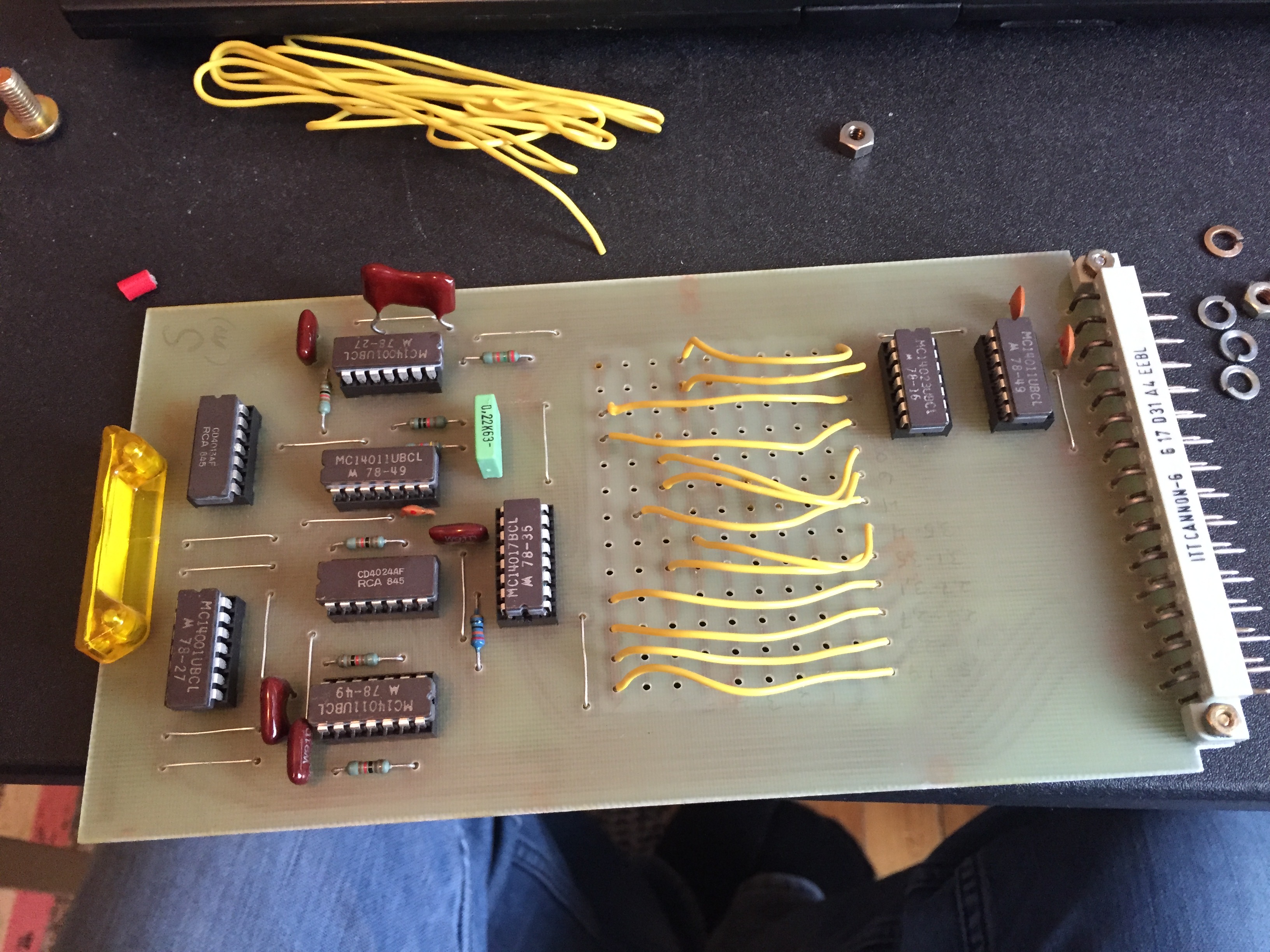
Above the tuner pre-set card is shown, each horizontal wire corresponds to a frequency-band, and the horizontal position programs where the tuner begins the search.
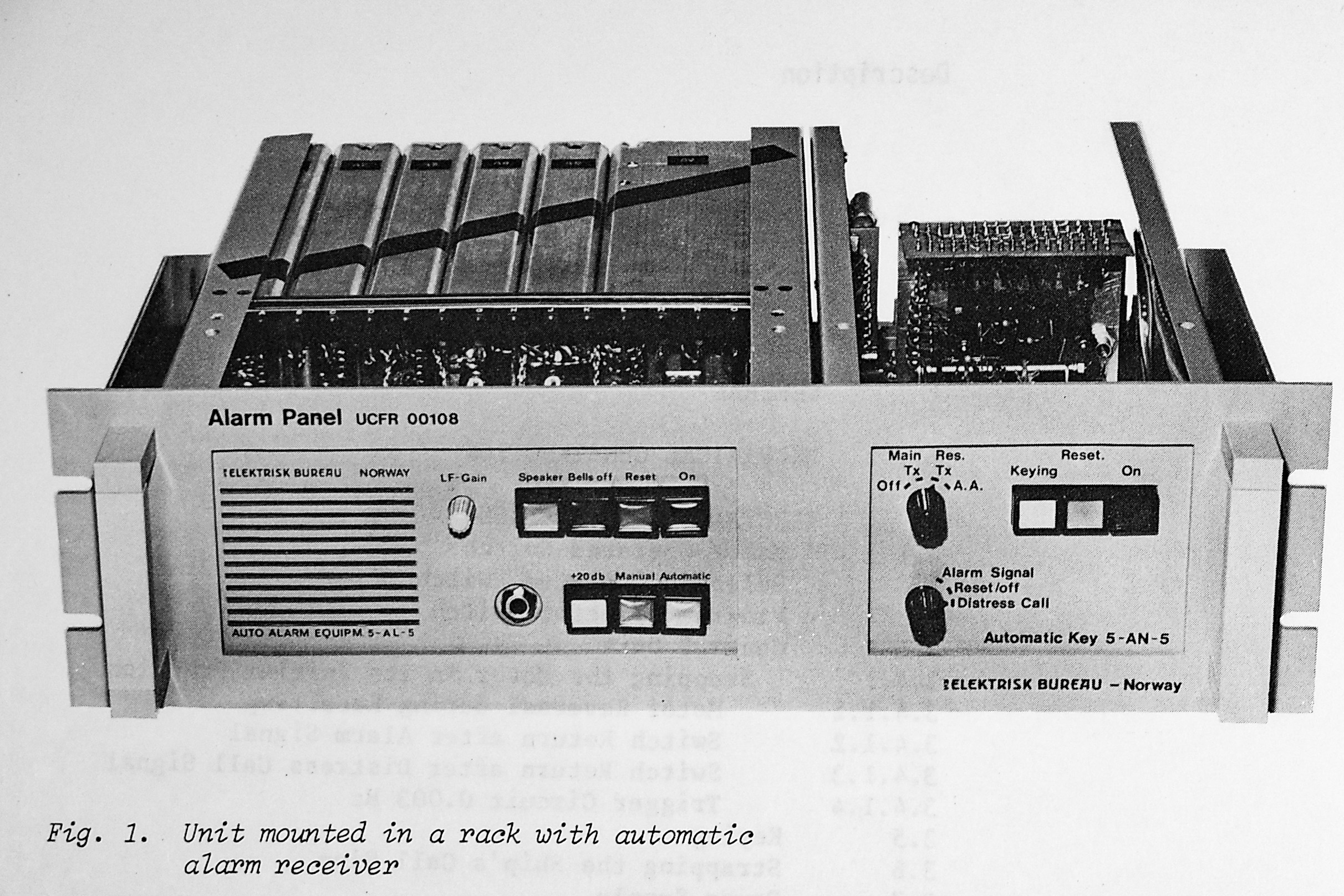
Alarm Panel
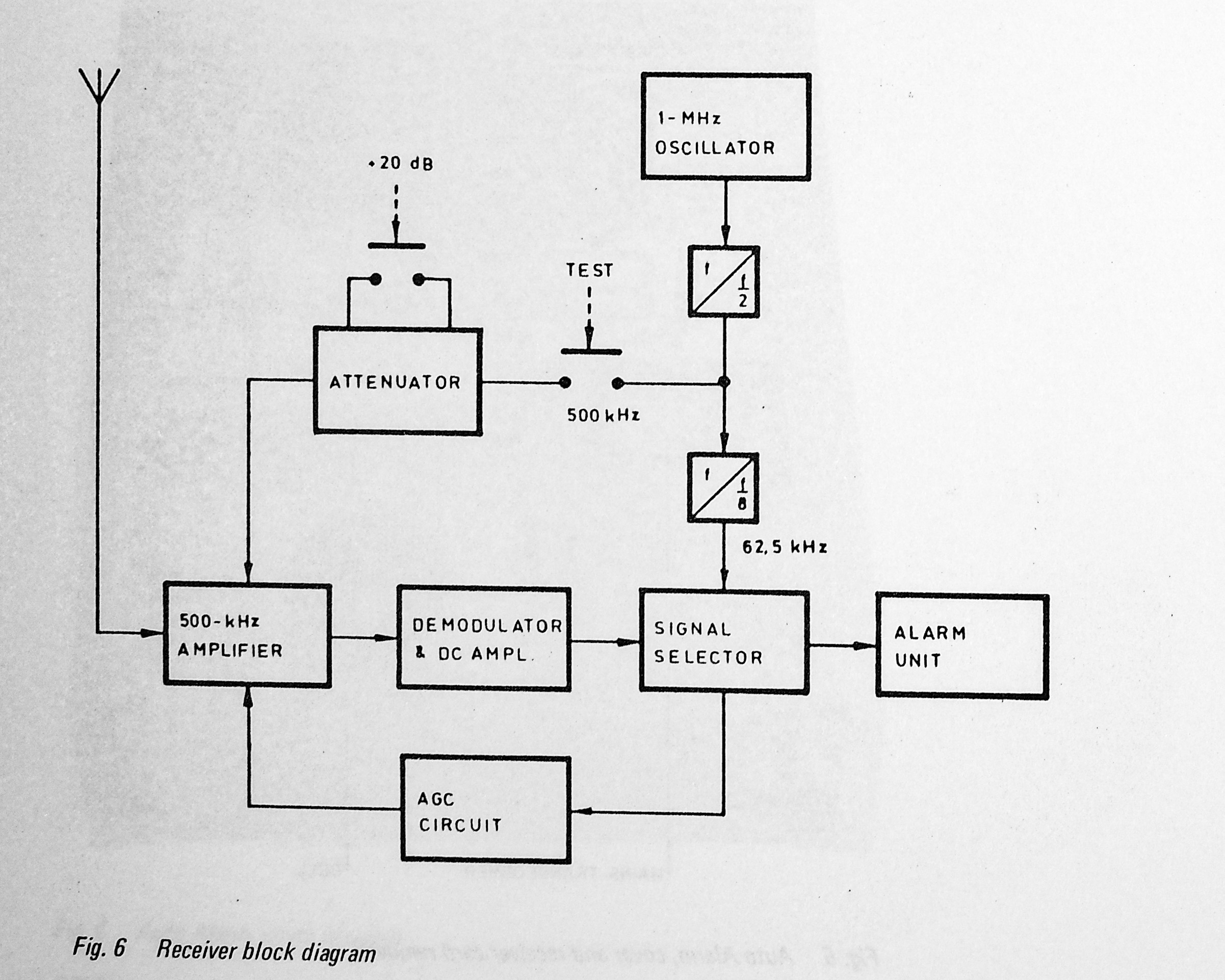
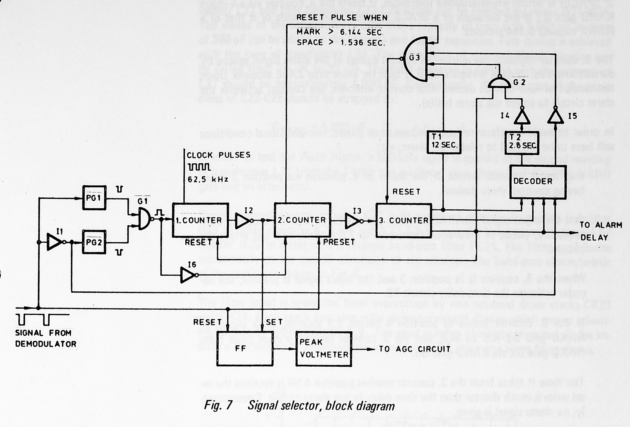
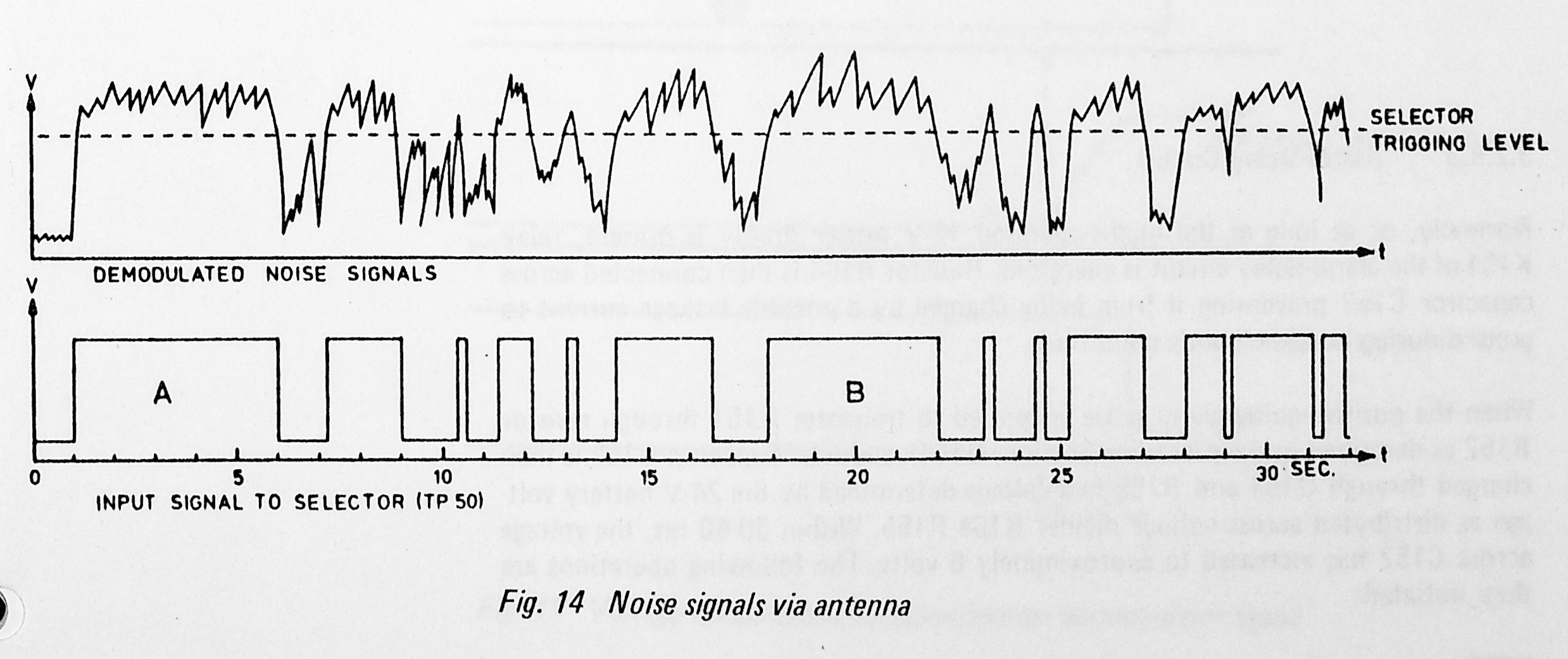
The Alarm Panel is a combined rack unit containing an Auto Alarm Equipment and an automatic 500 kHz CW distress signal receiver.
This is fairly complex, and automatically detects a standard distress sequence and sounds an alarm to alert the operator. It's built from a fairly complex mixed signal state machine.
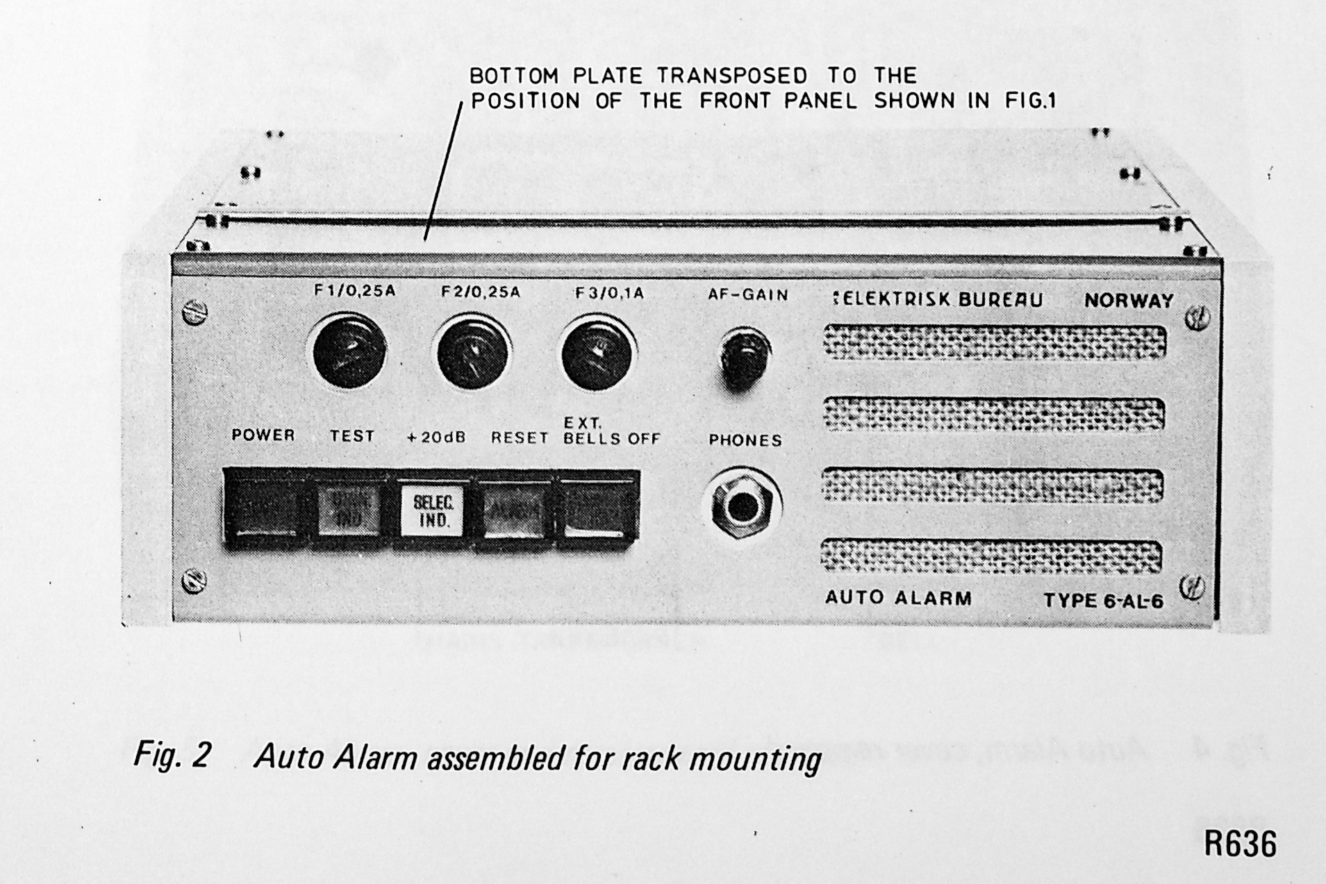
The other piece of equipment in the Alarm Panel is even more dire, it's the Automatic Key, a device can automatically transmit a CW distress call including ship callsign on the 500 kHz transmitter. The keyer seem to be built like a music box, programming of callsign is done by soldering wires in a matrix, and a rotary encoder is rotated to read out the programmed sequence.
This is basically connected in parallel with the morse key, and can be switched to either of the two transmitters.
Telephone Part
The radiotelephony exchange was relatively simple in the basic form, and could be used mostly standalone, or as part of a more complex system including a conventional telephone exchange for internal use.
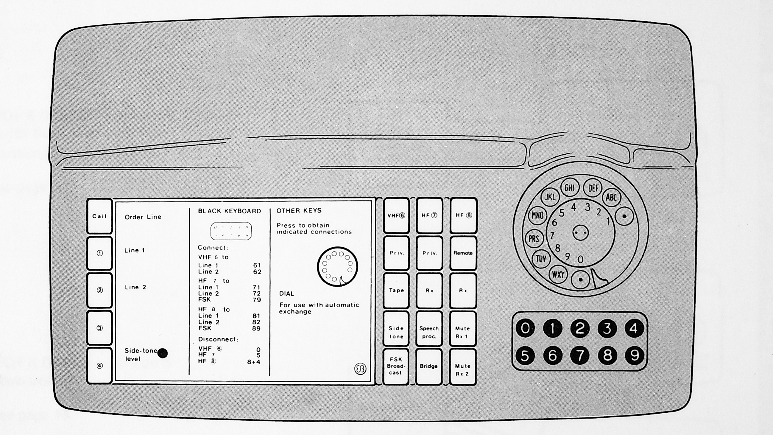
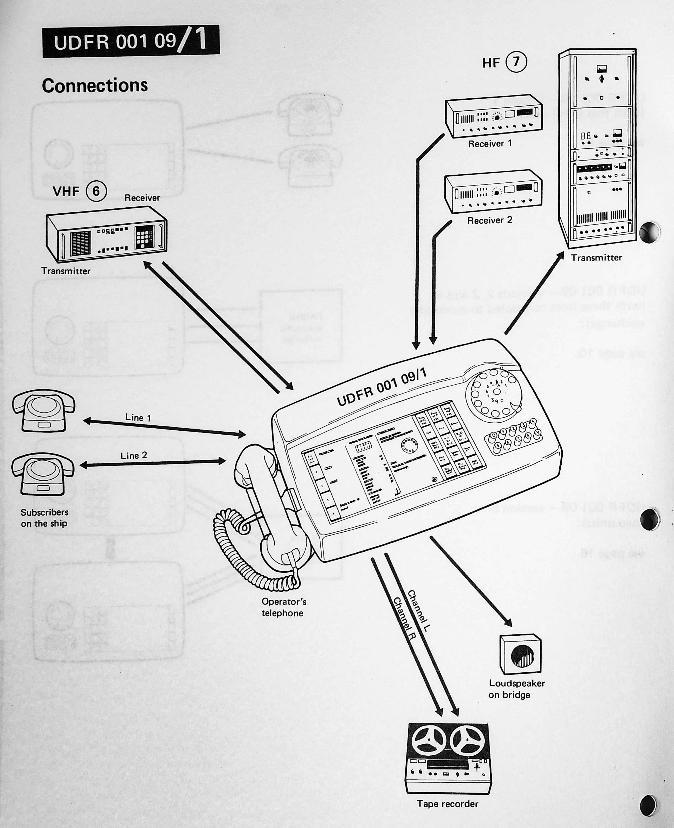
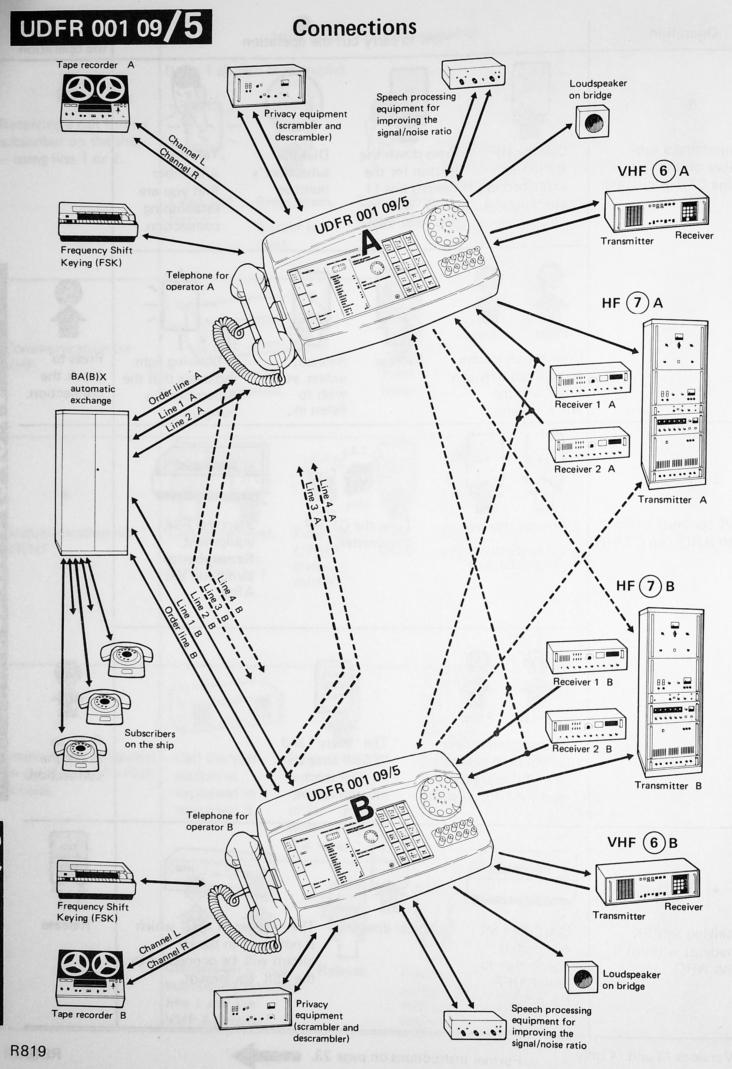
The basic telephony setup would likely use 4-wire telephones for use on VHF and HF in general. For more sophisticated systems it would technically be possible to patch duplex phone calls to either 2-wire or 4-wire phones elsewhere in the ship.
We also note that recorders, speakers, and FSK (telex) equipment was common, and some users may also have fitted voice scramblers or speech clarifiers. Unfortunately I don't have documentation on that part of the system.
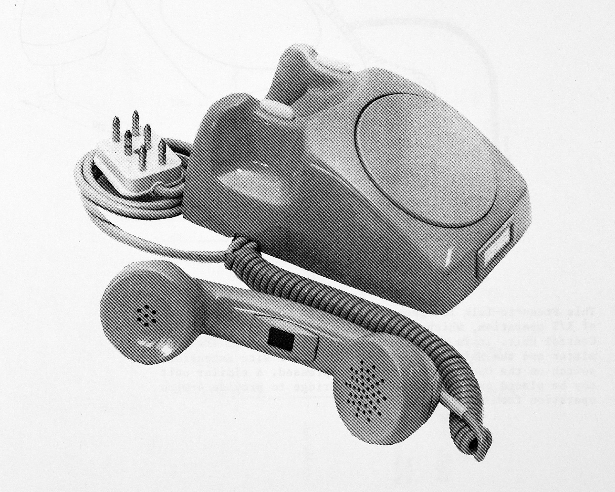
The 4-wire telephone system was likely used to avoid crosstalk between the ship side telephone speaker and microphone, which could cause issues. The 4-wire systems appears to be capable of detecting both off-hook states and key-states in the handset, as well as either ringing a bell or lighting a lamp on the telephone.
The chassis of this telephone seems identical to the then current Norwegian standard telephone, minus the rotary dial and with the addition of PTT.
Receiver Usage
The receiver has a very wide coverage, this is slightly strange but likely intended for suit a wide range of applications. A typical lower cost ship receiver would only cover e.g. LW/MW from around 150 kHz and up to e.g. 4 MHz. Coverage down to 15 kHz would allow monitoring of e.g. OMEGA/Decca positioning signals, submarine transmitter links, time signals, and LORAN. The inclusion of the LSB mode is a mystery, the Orion system didn't support LSB transmission (though I later modified it to do so). It may have been intended for some type of intercept usage as well.
I'm not sure why the Drake RR-1 is shown in the console picture; this appears to be a slightly worse receiver than the 3021N for most purposes.
Reception of time signals could be useful to ensure the ship's master clock maintains appropriate time accuracy. This master clock would likely be used for celestial navigation. Despite the availability of e.g. OMEGA, DECCA, or LORAN receivers (or perhaps even Transit satellite navigation), I imagine most sailors in the 1970s would still verify the electronic positioning system fixes with celestial navigation.
Telephony
For larger ships a full duplex telephony connection could be established in the high MF and HF bands.
At this time setting up such a call would involve an operator at each end talking to each other to agree on frequencies to use.
In this system a separate antenna would likely be used for transmit and receive, likely at opposite ends of the ship if possible. The Marine HF bands have a number of duplex allocations in the 2-22 MHz range, and for optimal capabilities a relatively complex filter set was used to block all transmit-frequencies across all the bands.
I would imagine this would be the sequence for establishing a telephony call:
- Officer calls operator to ask for a ship-shore telephone call, lights a cigarette (since it's the 1970's)
- Radio operator puts out a cigarette then immediately lights another (assume minimum 1 cigarette per step for following). Selects and tunes a transmitter and receiver pair to the nearest shore-station frequency
- Operator calls the shore station, identifies the ship, and requests a telephone patch
- Shore station assigns a frequency pair after verifying billing information
- Operator pushes a bunch of buttons and possibly moves coaxes on a switchboard around to assign a receiver and transmitter to this link
- A transmitter would be assigned to a given antenna, tuned to the right frequency, and then either manually or automatically matched to the antenna
- A receiver would be assigned a different antenna and tuned to the frequency, and the preselector and duplex filter would be tuned up
- The receiver would likely also be connected to the antenna through a narrow external band pass filter to reject the transmitter frequency
- Operator likely uses the local handset to test the two way link, talking to the shore operator
- Shore operator connects the assigned radios to the telephone network, may also act as a phone switchboard operator after this or pass the call on to another operator
- Ship operator would connect the transmitter and receiver to a given internal telephone line, then call the officer back to inform them that the call is ready
- Officer would likely instruct the shore operator which number to dial and be connected to his mistress
- After termination of call, inform the ship operator to tell the shore to tear down the call, and free up the radio systems for other uses
- At every step above some type of log would be kept, unless sufficient payments were made
- Everyone could monitor these calls if they wanted, the radio link would likely be either AM or SSB
As far as I know this feature is still possible with modern communications systems, and is still required to periodically be tested by the operators. These days I imagine most phone calls use satellite systems or VHF.
VHF radiotelephony is also commonly used for telephone calls when close to shore, but this normally uses a VHF frequency pair with the ship station generally operating in half duplex.
Realistically these days most areas with VHF coverage also have cellular coverage so I imagine that is preferred for personal calls.
Telegraphy/Telex
Another important feature supported by both this receiver and contemporary transmitters is telex (teletype(RTTY)). This receiver has the 1 kHz filter bandwidth suitable for this use, but an external telex-modem would be required. As seen above, the telephone exchange could connect a given receiver and transmitter to FSK equipment.
One or more receivers would be used to receive NAVTEX or similar morse or telex messages, with such things as navigational hazards and weather messages.
Another use is the reception of fax messages, the German weather institute still transmits weather charts via radiofax, which could be received using a special FSK demodulator and a printer.