Retuning a Procom BPF 2/3 150H Cavity Filter
A Procom VHF cavity band-pass filter was donated to the shack, and some work was done to retune it to 145 MHz.
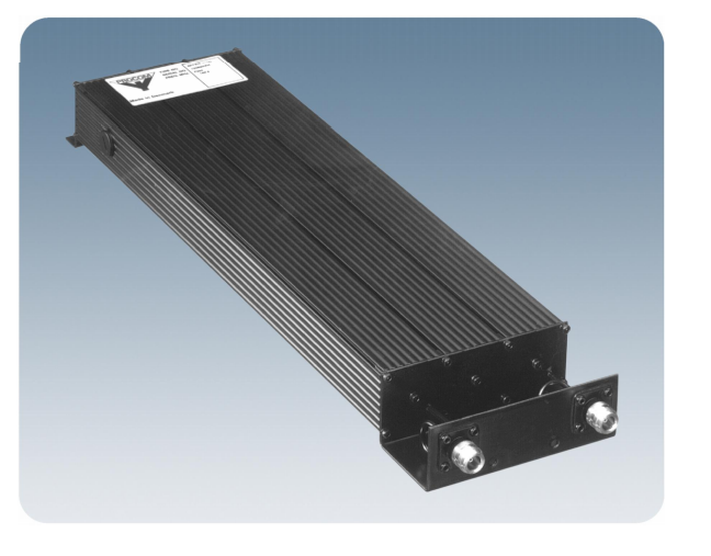
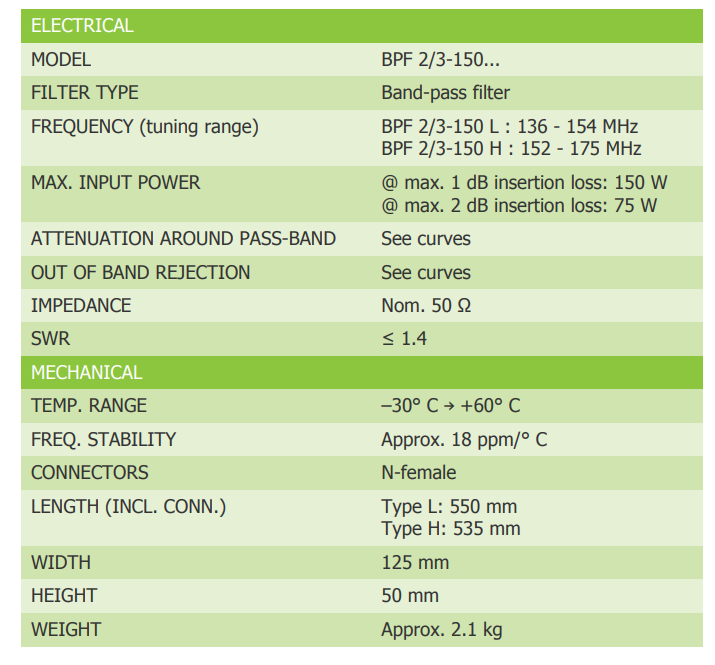
This filter is a cavity filter made from aluminium extrusions and some steel pieces. The data sheet can be found here: http://www.skymasts.com/_/uploads/bpf-2_3-150....pdf
For various reasons hams are much more likely to come across the VHF high band version rather than the more appropriate low band version. The biggest source of surplus equipment is Police/Fire/EMT installations, who mostly used 158-174 MHz or so before switching to TETRA.
The 150H version is intended for 152 MHz+ as can be seen below:
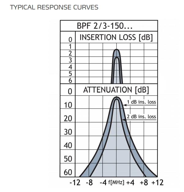
A neat feature of the filter is that the cavity coupling can be adjusted to change the effective Q factor of the filter.
Because this is implemented with a cross-screw through the centre element, the capacitive tuning lug will short on this screw if you try to tune it far below the specified range.
Modification
To retune the filter, the easiest fix is to slightly extend the metallization of the center element to cover a plastic spacer near the tuning end. This can be done with some copper tape:
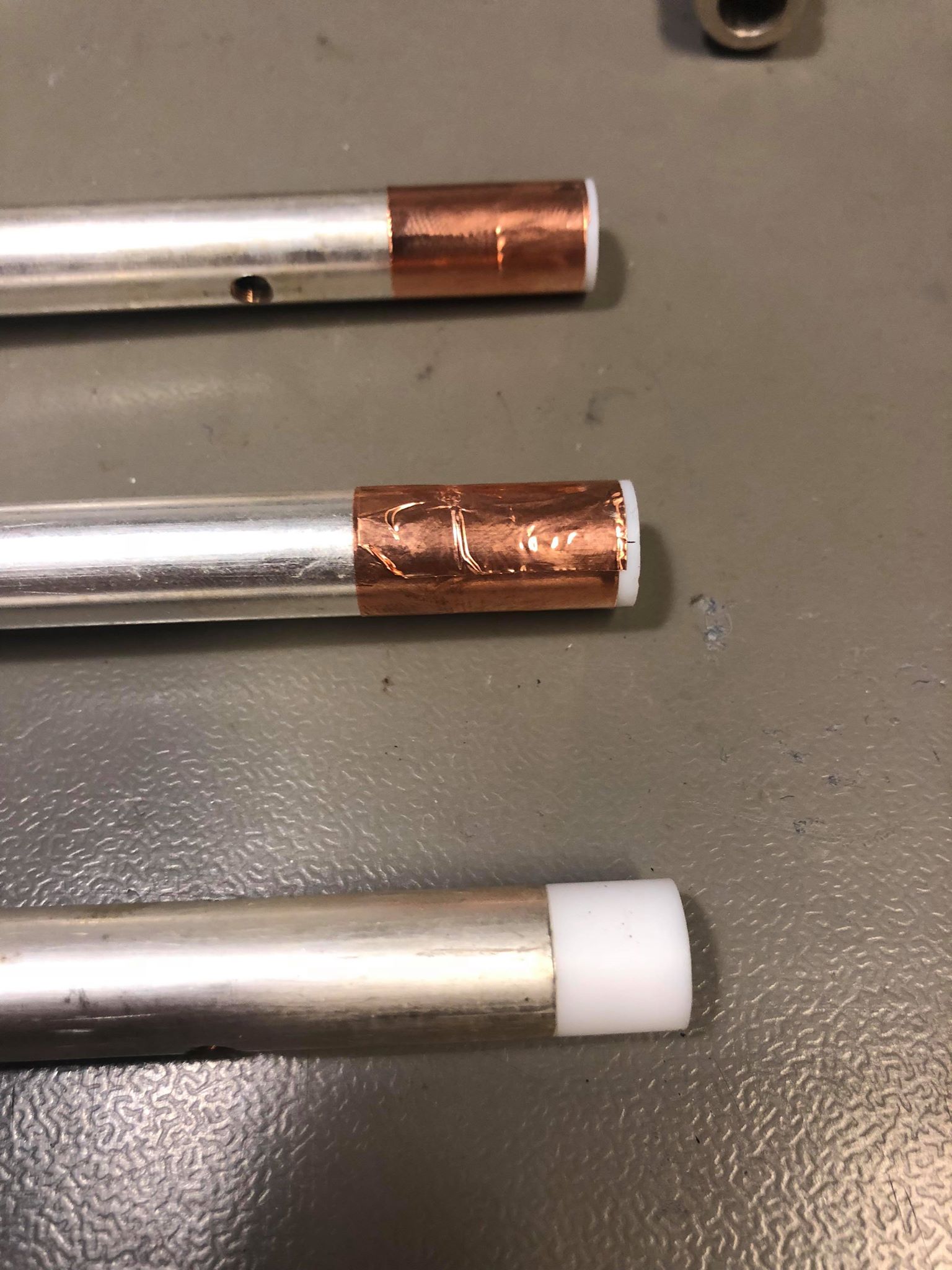
I superglued the white pieces in place before adding the tape, they can be accidentally pulled out otherwise if the radials are misaligned.
Leave a small gap near the top like in the picture, this is necessary to avoid shorting out the radial to the end plate. This end is a high impedance node, so the resistance of the metallisation is not critical; make sure you have a decent overlap with the tape (we rely on the sheet capacitance in this case).
I added some solder along the edge of the tape, but couldn't wet the radial using a normal soldering iron.
This mod has not been tested for temperature coefficient, but this will most likely be reasonably ok.
Test Results
Tuning the filter is fairly simple, the center cavity has the largest effect on the center frequency, and the edge cavities largely control the stop band performance.
Be careful with the tuning screws to damage the threads; they're brass so they're fairly easy to damage. I had to file down some areas with a small diamond file to get them to go reasonably smoothly.
Tightening down the locking nuts is mandatory since the thread has a lot of slack, which will cause a bouncy connection otherwise.
It's possible to asymmetrically tune the filter to give a sharper attenuation on one side if that is desired (but this works best with narrower bandwidths). It's also possible to increase the Q a fair bit at the cost of higher attenuation.
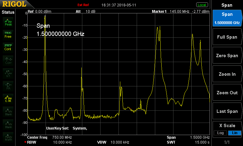
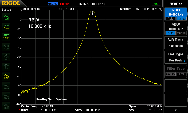
With the tuning configured to cover 144.8-145.8 within 1 dB, I got the following result:
-6dB frequencies here are 143.7 and 147 MHz with –60 dB approx 12 MHz away on either side.
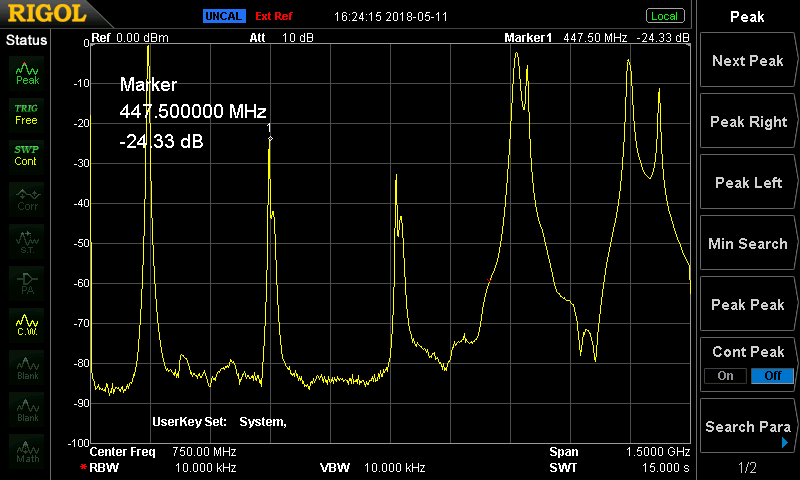
The near band attenuation is very good, more than adequate for most purposes. However, it does let some harmonics through; note that the first harmonic shown is not a harmonic of the pass band (it should land around 435 MHz, not 447).
The biggest peaks are around 800 and 1080 MHz, far outside the intended stop-band.
Retuning for a narrower pass-band by reducing the coupling between cavities gives a higher insertion loss, but also positively affects the 446 and ~800 MHz performance.
Performance was also checked on a wider bandwidth analyser and the performance above 2 GHz is pretty chaotic (no picture available).
The filter can be tuned to a 6 dB BW of approx ±500 kHz with decent insertion loss, or a wider range as shown above.
Other Notes
Don't try to clean any of the black parts with solvents, the coating is soluble in isopropanol and will get everywhere.
The original screws are kind of crummy, but not hugely so, try to avoid using ball end hex keys if you can (don't use the ball-end to tighten or loosen the screws).
The wide band attenuation performance is perfectly adequate for VHF equipment but you'll need additional filtering if you wanted to use this as a preselector for a RTL-SDR dongle or similar. Otherwise you're quite likely to get interference from LTE and GSM traffic.