The Ascom SE-140, programming and other mods
I bought some Ascom SE-140s and figured out how to program them without buying a 386 computer and floppy disks.
Table of Contents
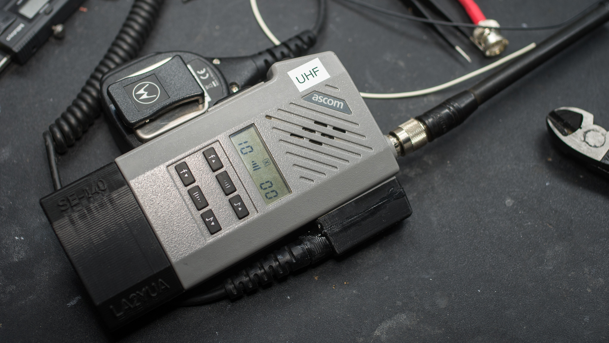
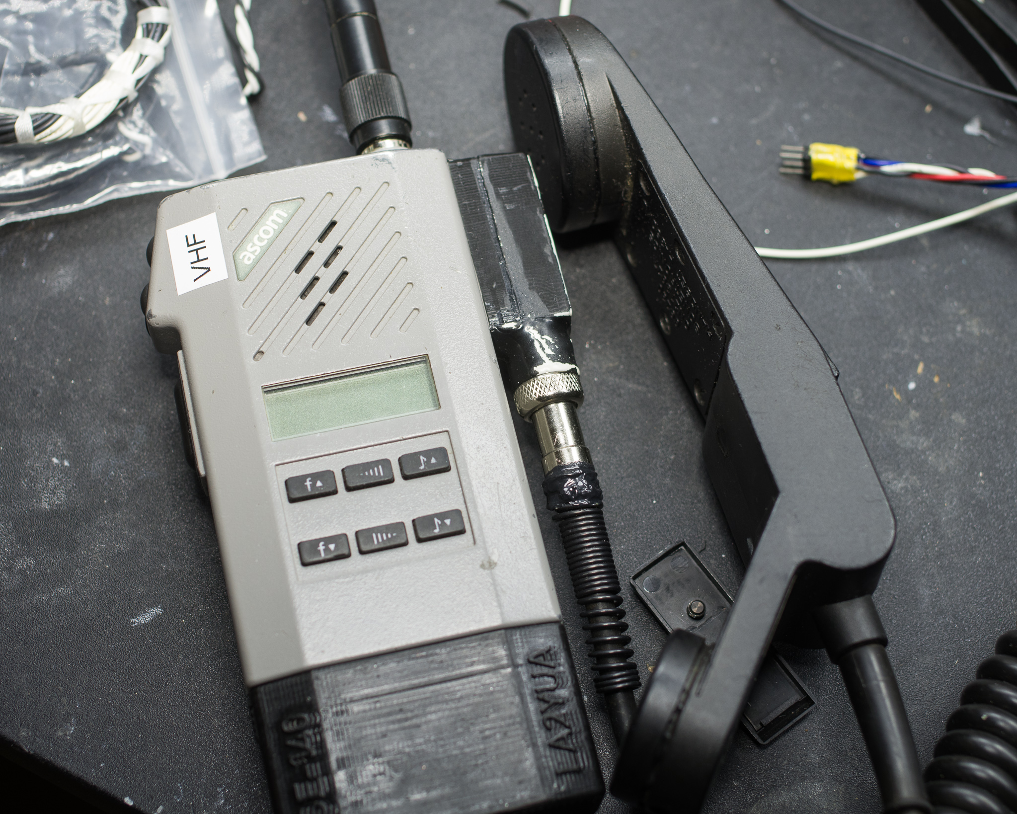
The Ascom SE-140 was a pretty popular professional radio used by many European public services and some other professional uses.
It's a largely basic early 90's system radio, featuring 5-tone and CTCSS, it has a CTCSS decoder built in which sets it somewhat apart from competitors.
What's nice about it is the lovely build quality, it's made from two die cast pieces of aluminium, IP54 rated and painted a lovely professional grey.
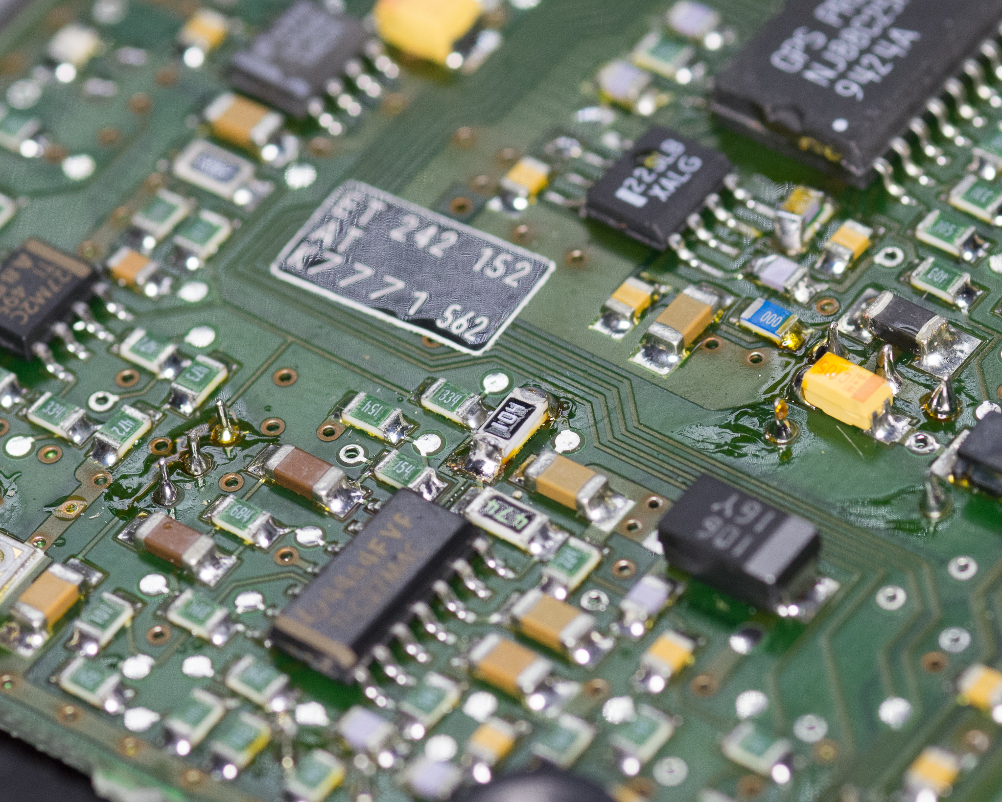
It also has a fairly sophisticated processing chain, using a mask ROM programmed Motorola processor (probably a 6800 MCU), a VLSI ASIC, and a TI DSP.
The ASIC is used for most control functions, while the DSP handles AF professing for both TX and RX, including filtering and tone detection/generation. The RF section is fairly standard but well implemented in a fully shielded can, protecting the delicate components from RFI, and repair attempts.
Programming Cable, Hardware
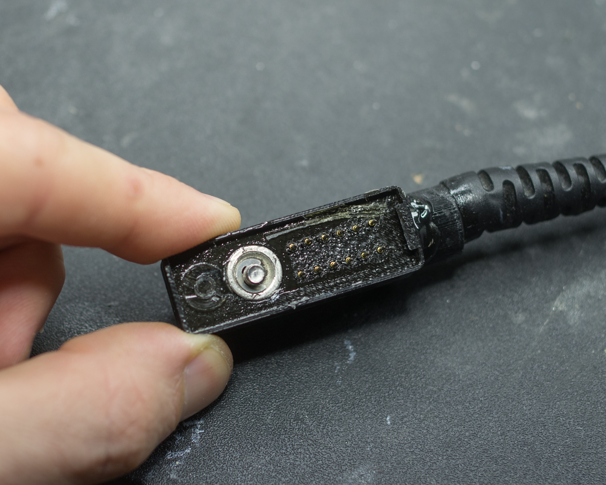
I made a 3D printed adapter block that connects to the aux connector using standard 1.05 mm spring pins.
It uses the cheapest style of pogo-pins, they are aligned, super glued, then soldered to wires. Final epoxy potting is a good idea for a permanent version.
A M4 screw combined with a bottom lip ensures a decent and secure fit. I suggest using an E-clip to retain the screw (grind a recess in the screw to make it fit).
As a UART I used and still recommend a CP2102 dongle.
An appropriate adapter print file can be downloaded via Thingiverse:
Ascom SE-140 Side Connector Adapter
Note that you'll also need the following:
- Adapter PCB - via OSHPark: https://oshpark.com/shared_projects/I6yi5Xcs
- M4x16 DIN912 screw (head type is important to make it fit)
- (Optional) 4 mm E-clip to retain the screw
- P75-B1 1.02 mm pogo pins (via eBay)
- Super glue+epoxy to assemble housing
- CP2102 or equivalent 5 V compatible TTL USB serial adapter
- (Optional) GX12 male/female connector (via eBay)
I like the CP2102 since it doesn't need special drivers in Windows 10.
Here is the pinout for the side connector:
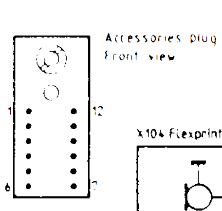
Of these, the following pins are important for programming:
| 9 | D-in | Connect to dongle TXD |
| 10 | D-out | Connect to dongle RXD |
| 12 | GND | Connect to dongle GND |
The adapter PCB also has an optional microphone preamp to let you connect 150 ohm dynamic microphones.
Here is the schematic and assembly film:
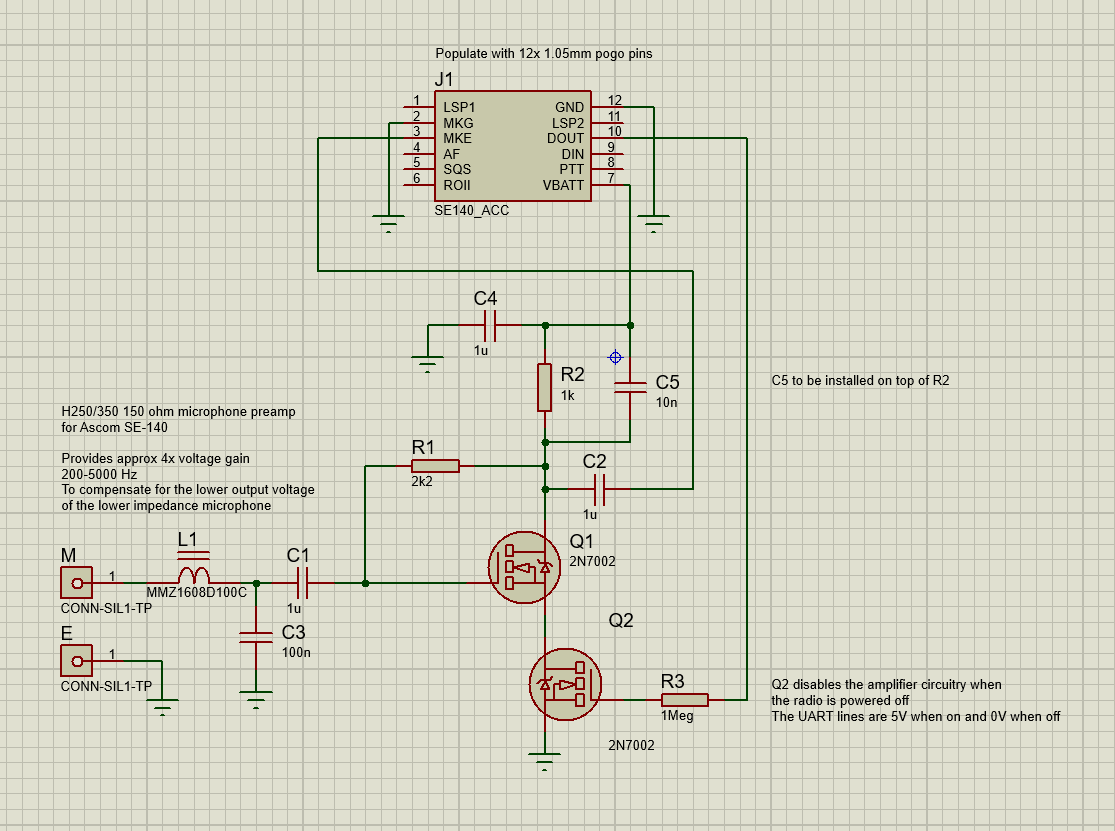
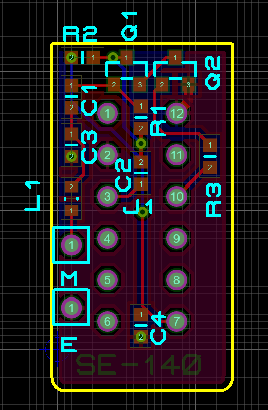
All passives 0603, 10 V or more. Note that R1 and R2 can be tuned to adjust the microphone gain. For electret microphones you don't need to do use this amplifier.
With the hardware done it was necessary to get the software running.
Virtualization attempts, DOS choice
I decided to attempt to use FreeDOS as my OS, it has a lot of nice features that make it very desireable to use it instead of a MS-DOS variant. That it's open source also helps.
I tried several VMs before finding one that worked properly with the IPP140 software.
- VMWare, runs IPP140 fine, but COM port pass-through seems to be broken in DOS (works fine in Windows 2000). Opening a COM port mapped to a host serial port results in an error.
- DOSbox, doesn't really run IPP140 well as it gave a number of error messages after navigating the menus a bit
- VirtualBox, COM ports work in the command line but initialization seems broken in the IPP software. It would hang when opening the radio programming menu.
- QEMU, my last choice because it's harder to use (no GUI, scary), but I was able to make it work in QEMU using COM passthrough and 486 emulation
So I used QEMU, getting it up and running wasn't super hard. Installing the software and getting it to run was pretty easy since I'd done it several times by that point.
Programming Issues
I had several issues with programming the radio, and some issues reading versions and programming from the radio initially.
I suspected this was related to a software timer loop running too fast for the radio to respond. It normally takes around 10 ms to respond to a command and QEMU doesn't have a very good CPU speed limiter (but it does have one! it also has some other nice features like curses output)
Using the logic analyzer I determined that the programming sequence would start, and run a sequence of write-read cycles against the radio. Each byte is written then the radio echoes it back, if there's no response or the readback is corrupt the software terminates the programming.
Some commands would take as much as 30 ms for the radio to respond, and it would then time out prematurely.
Using a disassembler, I was able to determine where the uart-read function was and modify the timer delay value, changing the cycle count for 0x1388 to 0xffff. This gives it much more margin without completely disabling the timeout.
After figuring out what values to change and finding a hex editor in DOS I made the change and successfully programmed my radio for the first time.
I was also able to confirm that the UART is initialised to 9600-8N1 by the software.
Note that after an incomplete programming the radio will display "P", and it must be rebooted by removing the battery before any other commands can be sent. When rebooted with a partially programmed EEPROM it will only show "0". Fortunately there doesn't seem to be any way to brick the radio permanently that I found, probably due to the mask ROM software and the built in checksums.
QEMU setup, installing IPP
I used QEMU, running the latest copy of MS-DOS.
A finished image can be downloaded here: MS-DOS_IPP140.zip
Running the emulator in Curses mode gives a nicer display since the DOS software only uses text mode graphics, the text will be rendered using curses on the host OS (so the fonts look a lot better on Windows 10). If you run into issues, SDL mode worked well for me.
Launching the emulator
The file msdos-ncurses.bat has some stuff you'll likely need to modify:
set PATH=%PATH%;"C:\Program Files\qemu"
qemu-system-i386.exe -display curses -cpu 486 -m 64 -serial COM8 -serial file:serial.log FreeDOS.qcow2 -fda IPP_140.flp -boot c -icount shift=5 -rtc base=1994-01-01T00:00:00,driftfix=slew
"C:\Program Files\qemu"
Change this to your qemu install directory.
-display curses
Remove this to launch Qemu in a separate window; you need to do this to do things like change floppy disks and parameters while the emulator is running.
-serial COM8
Change COM8 to your serial port emulator, or remove if you just want to test the emulator without serial enabled.
-serial file:serial.log
The second -serial flag sets the COM2 port output. In my case it logs to a file in the same directory as the emulator files. My setup uses COM2 for the printer output from the programming software.
FreeDOS.qcow2
Filename of the virtual hard disc file.
-fda IPP_140.flp -boot c
Connect the floppy image IPP_140.flp, and boot from the C drive (hard disc).
After startup, issue the following commands to start the IPP140 software:
> CD IPP
> IPP140
Notes on Programming
The built in help is pretty ok for this kind of software; the software lets you press F1 to look at key shortcuts etc.
What may be less obvious is that pressing F2 gives you the context sensitive help with explanations for the specific page you're on.
The speaker is off by default and must be opened by a tone signal; when the speaker is on it will then be noise squelch controlled until a timeout occurs.
The Qemu image provided has my programming included for UHF and VHF types, and you can load these via the menu system.
CTCSS decoder
When using CTCSS receive it is important to disable the 5-tone receiver, since the signalling mode seems to be an AND. So if you have a 5-tone decoder and CTCSS decoder active on a channel, both must detect a tone to activate the speaker.
Disabling the 5-tone RX makes CTCSS squelch work about as expected. Setting the squelch sensitivity to standard makes it much quicker to close.
If most of your channels are TSQL, set the speaker to mode B and turn off the speaker timeout. In this case the speaker button will work as a normal squelch-open button, and the speaker will only be active when a tone is received otherwise.
This also works for channels with no TSQL, as long the the tone decode is set to 0.0 Hz the radio will just use the noise squelch.
1750 tones
You can make 1750 tones with any of the three 5-tone encoders. With CCIR code tables you just send an 8 for 1747 Hz. Note that the repeat tone is 2100 so sending 88888 will give alternating 1750/2100 tones.
The standard workaround is to go to the radios 5-tone encoder settings and configure it to output the first tone for 8 tone periods when starting a transmission instead of just silence. Then just program a tone squence of 8xxxx where the Xes are don't care, pick something that sounds nice.
In the general settings you can also choose if the 5-tone encoder should transmit a subtone (setting encoder to either all PTT or all TX).
Channel Spacings and offsets
The radio was made in 12.5 and 20/25 kHz variants, these likely differ in what IF filters are used. I did not find any issues with setting my 25 kHz variants to act as 12.5 kHz variants. It's likely the PLL implementation is the same for both versions.
Note that the radio can't do mixed deviations, the max deviation must be adjusted using the analog trimmer pots inside the unit (See service manual and below).
When programming my UHF variants I found that a 2 MHz offset was always applied to the TX frequency; programming a radio for 433.5 TX/RX made it RX on 433.5 but TX on 431.5.
I couldn't figure out why, so I just program the TX 2 MHz higher than the RX to work around it. It might be due to selecting the wrong type (400-440 vs. 430-470).
Hardware Mods
12.5 kHz operation of 20/25 kHz models
Replacing filters in the radio is left an an exercise to the reader, but it is possible to adjust at least my VHF variants down to 2.5 kHz max deviation using the built in trimmer.
Both my UHF variants required replacing a series resistor between the MOD line going to the RF board and the RF board mod amplifier. This is not undesirable for the VHF version too as this will improve the adjustment range.
Pictures of where to mod this resistor are coming.
It is however very important to adjust the RX deviation sensitivity for operation on 12.5 kHz channel repeaters since the subtone decoder by default cuts out around 320 Hz deviation.
ETSI specifications for CTCSS tones in this environment is 300-500 Hz deviation, meaning your tone squelch may not work on some repeaters.
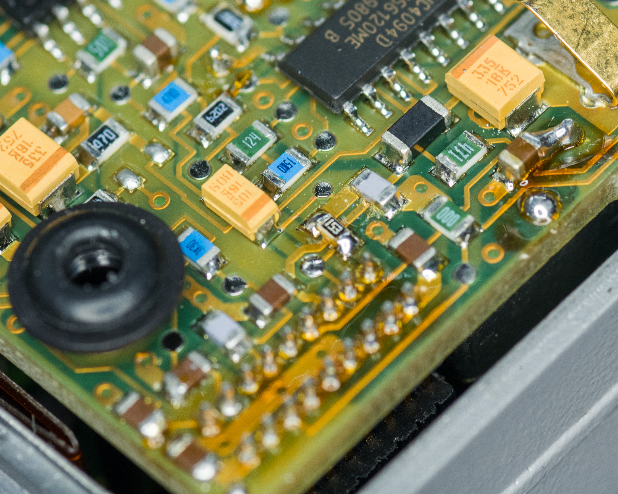
Modify the 82 kΩ 1206 resistor to approx half the original value by tacking a 82 kΩ±20 kΩ resistor on top of it to improve the CTCSS decoder sensitivity and improve audio gain for narrower bandwidths:
My radio cuts out at around 150 Hz deviation which is well within spec with this mod.
Equivalent mod for UHF variant:
To reduce the max deviation in the UHF variant, mod the resistor shown below:
Antenna Connector
The standard antenna for these radios is a custom M5 thread. If yours are like mine then the antennas are basically just waiting for an excuse to fall apart due to plastic aging.
As a stop gap measure, use a big shrink tube and some glue to cover the original plastic. I did this with my antennas while waiting for the TNC plugs, self vulcanizing tape also works reasonably well to stop bits falling off too frequently.
The M5 antenna connector in the radio has a standard thread for panel mount BNC/TNC plugs (TNC antenna was an option so this makes sense).
To replace the plug you'll need to remove the PCBs from the radio, use a Torx 8 driver to remove the four screws on the back, take off the rear plate, then undo the one screw holding the PCB to the chassis near the antenna connector. After that the entire RF+Logic board stack pops out really easily. Be careful not to damage the spring clip that connects the antenna.
Unscrew the M5 connector and screw in a TNC connector. The center pin on a TNC panel mount is slightly too long, trim off the solder cup from the TNC and it should fit. Make sure the center contact on the TNC is clean and gold plated to avoid issues.
Use Loctite 577 near the top of the thread to seal the adapter against water ingress.
Adjusting the Radio
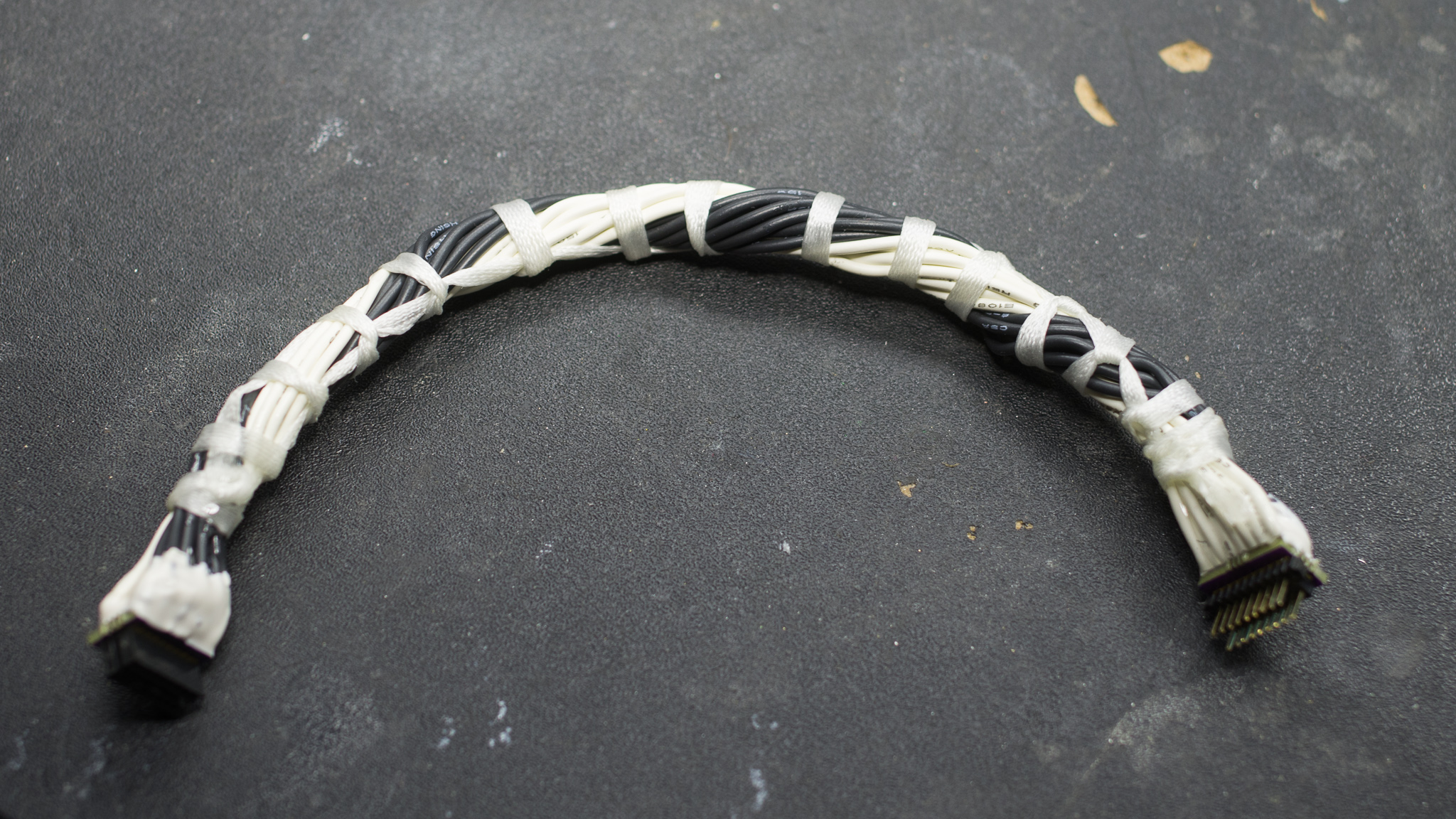
To access adjustment points, make a jig cable. You'll need some 1mm pitch pin and socket header strips to make a male-female 2x10 pin header extension cable separate the RF and Logic boards. These can be bought off eBay, though they're a fair bit more expensive than 2 mm or 0.1" strips.
I have shared an adapter PCB that can be used to hold the pin strip and female header: SE140_Jig
Assembled with epoxy potting it looks like this:
Squelch adjustment is done via the software, it simply specifies tuning an unused channel and removing the antenna then it auto-tunes this.
To actually use this you'll have to screw the CPU board into the chassis to connect the flex inside the radio.
Use a panel mount solder tabbed BNC/TNC, you can bend the ground wing down and drill a hole through to screw it down to the RF board mounting screw hole to get ground. With careful bending you can make the center contact sit on the contact spring to get RF out.
You'll need a set of M2.5 screws of various lengths and at least one M2.5 nut to do this.
Use the programming cable adapter above to make a breakout cable for speaker+microphone+PTT to connect the radio to your service monitor.
Making new Batteries
A new battery can be made a number of ways. I went to the trouble of modelling it, and my design can be 3D printed if desired.
A more solid battery case could be made by doing some careful bending of sheet metal for example, combined with 3D printed or machined parts where necessary.
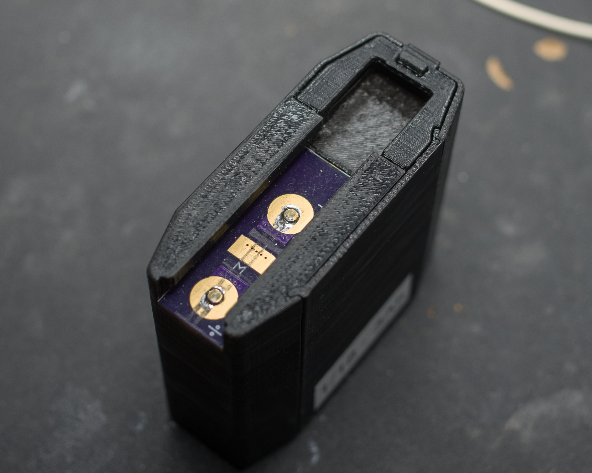
A small PCB can be ordered via OSHPark, this contains the contact pads for the radios battery terminals. A PCB like this should ideally have hard gold, but the ENIG is good enough for most uses. If you really care you can solder a more suitable material to the pads to act as the contact point. I found some 2.5 mm pogo-pin pads that I soldered to the terminals.
Link to buy the PCB via OSHPark: SE140_Bat
Link to download the STL files for the standard and short batteries: Ascom SE-140 Battery Cases
The battery clip is simply super-glued in place, but this battery has pretty tight clearance on most of my radios so it's mainly there for show.
The PCB also has pads for 0603 capacitors between the +, middle, and minus terminals to try to reduce EMI. I suggest 10 nF or higher 16 V higher, X7R dielectric.
Note that I added the middle pad, but I decided not to wire this since I had room for an internal balance charger.
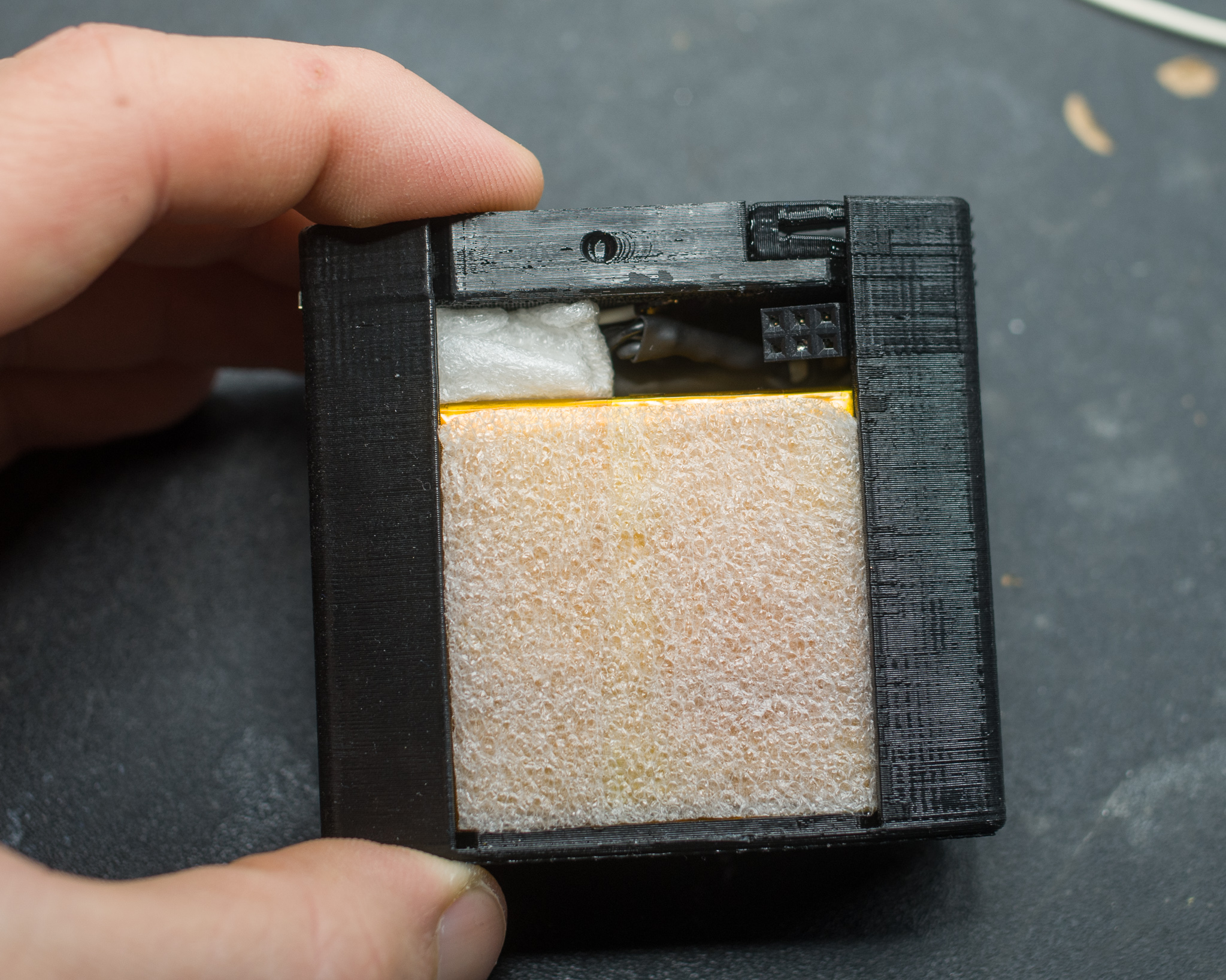
The original battery case can easily hold 4x504050 size batteries (50x40x5 mm), typically 1500 mAh per cell. This would yield a 3 Ah 7.4 V battery. Approx 3x the original capacity of the largest battery available. I also designed my 3D printed case to hold 4 of these batteries (though they can be a little fiddly to get in).
Estimated battery life using MFG figures:
- 60+ hours in sleep mode
- 15 hours of listening (continuously driving the speaker)
- 2.5 hours of 2.5 W transmission or 3.75 hours of 1 W transmission
The original batteries are pretty annoying to disassemble, the front piece can be removed somewhat non-destructively but the battery cells are silasticed in pretty heavily to avoid rattling, and you have to break the glue bond to get in there.
The small pack is 1 Ah, and holds 2x102050 batteries. I prefer the small type for most uses.
Charging the new batteries
To charge the new 3D printed case you'll want to use a balance charger.
I had room to fit a 2x3 pin female header, using a pinout looking into the female port of the header:
| B+ | KEY | B- |
| SENS+ | SENSM | SENS- |
Key is a female pin filled with solder, remove the matching male pin in the charger cable.
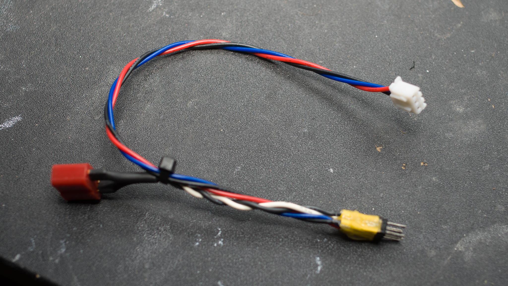
A matching breakout was made to go to a 3 pin JST for the SENS pins and a T-connector for the battery current.
Charge at or below 1 A to avoid voltage drop issues.
Adding a Belt-Clip
The Kenwood TK-378 belt clip can be bought in bulk at very low cost off eBay. It's a simple flat spring piece with two holes for mounting.
Installing it is a simple matter of drilling and tapping some holes, you'll need very short M3 screws (3-4 mm thread length max), and I suggest applying some sealant like Loctite 577 or silicone glue to the inside after installation.
If you don't have short M3 screws, use the electricians washer stack to compensate.
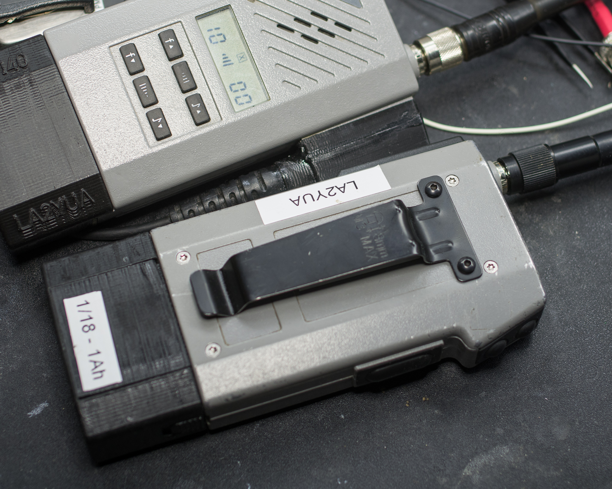
Note that it's best to place the clip so that you can still access the radio screws.
Low Battery Warning
With Li-Po packs the low battery warning level should be adjusted down somewhat, I suggest 6-6.2 V for a 2S pack. Normally the threshold is adjusted for 6.4-6.6 V, but that would leave a fair amount of charge left and the radio beeps intermittently when the input voltage is too low.
This adjustment is highly annoying to perform, since there is significant delay and hysteresis.
Other Issues
If the radio won't power on at all, check the fuse at the bottom of the radio.
If buttons are bad, clean them. The front panel buttons can be cleaned using normal electronics cleaner on the rubber pads. If that's not working and the conductive coating has rubbed off, the final solution is to stick some pieces of aluminium tape on the rubber pads.
The PTT switch was bad on one of my units, spraying electronics cleaner in the switch plunger and cycling it resolved the issue (at least temporarily). If you suspect the PTT is bad because it won't transmit, try pushing one of the tone-call buttons and see if it transmits then.
If the radio powers on but only displays a single "0", the programming has been lost, it can be reprogrammed using the normal method.
External hand-mic
I have made two accessories for this radio, a H-350 handset adapter, and a Motorola hand-mic.
The H-350 handset has a balanced speaker input, so it's simply connected directly to the speaker output. You need to build the accessory plug above including the microphone preamp for this handset.
I mounted a panel mount GX12 6 pin connector inside the adapter with epoxy, and fitted the plug connector in the handset cable for this variant.
Muting of the internal speaker is done via a magnetic relay that is located near the M4 screw. For the H-350 build I didn't fit any magnet since I want both to emit sound, but for other applications you'll want muting.
I used an old ring magnet with a 4 mm hole and retained it with an E-clip:
For the Motorola handset, I cut off the XPR plug and soldered wires directly to the pogo pins, just using the PCB as a support bracket. A lot of epoxy is used to hold everything together.
Warning: the speaker output of the Ascom is balanced, and sits at around 4 V DC to ground. You can modify the handset to drive the speaker in balance if you want to. However, if you want to use the external 3.5 mm earpiece jack you NEED to remove the DC.
I modified the handset itself with AC coupling caps and drive the speaker and earpiece output single ended at the expense of some loss in volume.
Note that Ascom originally also had the leads going down instead of the more common up; this makes a lot of sense since the antenna would otherwise be right next to the cable (did you notice that unlike nearly every other radio ever made, the Ascom has the antenna on the right side of the radio?)