Adding Optical I/O to the Sony MDS-E12 MiniDisc Recorder
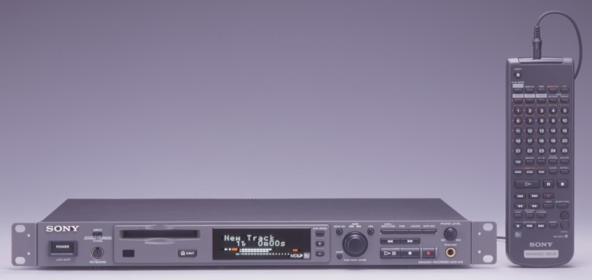
I picked up a 18 year MiniDisc recorder and restored it a bit, and added some optical I/O to it.
Table of Contents
I've always liked MiniDisc as a format, my first proper portable media player was MiniDisc and I loved it. It was significantly less bulky than equivalent CD players and battery life in playback was excellent (I very quickly learned that recording on battery was basically not happening).
To transfer CDs I used my PlayStation 2 and an optical cable, which provided automatic track splitting.
As such adding a MiniDisc recorder to my rack was something I wanted for a long time but never got around to getting one due to the price of a proper professional unit. I picked up a MDS-E12 off eBay for a very good price a few weeks ago.
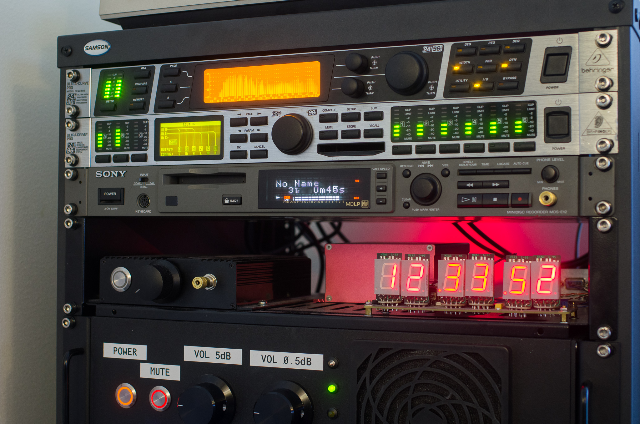
My current processing system is (Source; digital optical or analog balanced) → DEQ2496 (general purpose signal processor) → DCX2496 (6 way digital crossover processor) → 6 channel custom power amplifier running in a tri-amping configuration. Originally the link between the DEQ and DCX was an AES3 digital one; that meant that interfacing the MDS digitally would require it to receive data from the optical out on the DEQ while inputting over the coax port.
I was initially going to this hybrid setup with coax out from the MDS but optical input, that was scrapped due to the limitations of the DEQ2496 wrt. digital outputs (the digital out can't be the true primary output, the digital out is primarily intended for recorders).
Due to that plan I did some work to add optical I/O to the MDS as well, and I've presented the work below.
What I ended up doing was simply using the AES3 I/O on the DEQ and routing that directly to the Coax ports on the MDS using some adapter cables, changing over to analog balanced between the DEQ and DCX.
This lets me tap off the recording output before certain processing is done in the DEQ (such as processing that is potentially only used to compensate for speaker characteristics). I also ended up moving certain processing that I always want active like dynamic equalizers from the DEQ to the DCX to prevent this becoming part of recordings (and then being reapplied upon playback from the recorder!). This is my goal with having two processors in any case; the DEQ should only apply source corrections, while the DCX should only apply speaker correction.
If you're reading this you may also be interested in knowing that the deck will happily accept 24 bit/48 kHz audio but will not accept 96 kHz. The output is fixed at 16 bit/44.1 kHz however. I consider it acceptable to run my setup at 48 kHz to allow recording digitally, since there's no actual difference in sound quality anyway.
You'll need a sample rate converter like the SRC2496 if you find anything less than 24/96 unacceptable or have sources that can't easily be controlled. You might also want to find another format to listen to if your ears can tell the difference.
Belt Replacement
There's one rubber belt for the ejection mechanism in this device, it's likely to have gone bad so you should order a belt and expect to replace it. The symptoms are insertion/ejection not working, and the unit making a fairly loud whirring sound when you try to insert a MD.
"recycling_electronics" off eBay sells new belts as of december 2017, but alternate belts could probably be found if needed.
Belt replacement is a pretty painless operation, my belt had lost all springiness so it was just sitting loose around the drive wheels. I was able to remove the belt and put in the new one by simply removing the MD drive unit and working from the front using a set of tweezers and a small flat screw driver to push the new belt in. This fortunately meant I didn't have to disassemble the drive, an undesirable prospect since the top cover also houses the write head.
The MD drive is attached via four screws and connects to the rest of the system over two flat flex cables, it's a very simple operation to remove it.
All in all it took me longer to remove the covers and plug it in than it took to replace the belt.
I have no idea how you'd go about getting a stuck MD out of the drive though.
2021 update: the belt stopped working properly after 3 years. This isn't hugely impressive in my opinion. The belt as removed was fairly hard though not cracked.
The good news is that removing a stuck disk was fairly easy. The metal tabs at the front can be pulled down to raise the disk, and it can be pulled out without excessive force after that.
230 V Conversion
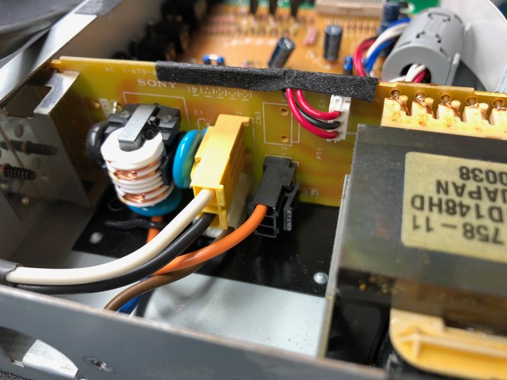
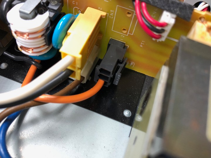
Modifying it to run off 230 V was fairly simple but required some reverse engineering of the schematic (it's one schematic for all input voltage variants, gets confusing). All the filter components are identical for 120/230 V versions so no component changes are required.
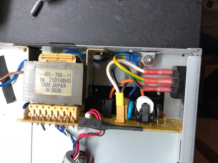
All you have to do is change over the orange jumper to the other side of the connector, as shown in the pictures below. It's held in with an integral flat blade spring, a small flat head screw driver can be used to get the pin out by pushing on the exposed metal on the side of the connector.
All MDS-E12/10s have the same transformer but only certain variants actually fitted a switch for mains voltage selection. Replacing the mains cord is also required when changing the mains voltage due to potentially different requirements for 120/230 V wiring. I used a grounded one for extra safety (the only reason equipment like this is double insulated is to prevent ground loops when used with unbalanced equipment).
There is a drilled tab right near the input which is suitable for chassis grounding, in my unit this hole wasn't tapped so you'll need an M3 tap to run through if you want a grounding lug.
I elected to install an IEC C14 inlet in the chassis, this was a somewhat tedious operation involving a dremel with a cut-off wheel. I also had to remove the PCB support bracket from the line filter PCA to fit it.
Cleaning
I used lemon acid spray to get rid of all the various glue residue on the outside of the device. It's a very effective non-toxic glue dissolver.
Optical I/O
The MDS-E12 has three inputs, unbalanced, balanced, and coax digital. The MDS-E10 is basically the same device but it has unbalanced, optical digital, and coax digital.
The same main board is used for both types with some BOM changes. The MDS-E12 has a relay to select the balanced input (which is on a different PCA). This is software controlled via a switch on the front panel.
On the E10 there are jumpers to bypass the relay, and the front panel switch controls the digital input sources. As an aside, it would be pretty easy to add balanced I/O as an option to the MDS-E10 by making a new balanced I/O board.
JW300 (jumper wire) sets the model no. to use.
Optical Out
Adding optical out to the E12 is a simple job, just install IC900, FB906 (ferrite bead, or jumper), and C917 (100 nF). IC900 was originally a GP1F38T, but the Toshiba TOTX147L is more available today and is pin compatible. Note the L suffix that indicates it's a 3.3 V model.
You'll need to remove a metal bracket soldered over where the optical I/O is. I believe this is there for purely mechanical reasons.
Note that initially one would think the pinouts of the two devices are mirrored, but this is due to the pin numbering convention being different.
Also note that you'll need to cut off the plastic support pegs on the Toshiba part since the original Sharp device had a different peg layout. Since the connector is screwed in this isn't a huge deal but you could always add a blob of epoxy to hold to the board after installation if you want to (wait until you know how it will align with the rear panel though!).
The more critical dimensions like the fiber port height and mounting screw location are identical.
Optical In via E10 mod
To support optical RX at the hardware level, IC901 (originally GP1F38R, use TORX147L), C908 (4.7 µF), C907 (100 nF), FB904 (ferrite), C909 (10 nF), R900 (470 kΩ), R917 (47 kΩ) must be installed.
However, the two digital inputs can't easily be ORed together, they are shaped up in an inverter and transferred separately to the MiniDisc ASIC on the BD board. Source selection is done via software in this case.
To support two digital inputs and select which one to use, the easiest solution is to change JW300 to convert the unit to a MDS-E10. This should change the function of the input selector to the E10 inputs, including optical and digital.
This will also remove the ability to select between balanced and unbalanced audio. This is controlled via a logic signal from the MCU that is connected to Q212 near RY200 on the main board.
The default state is unbalanced. To add a bal/unbal switch, remove Q212 and wire a switch between the collector and emitter pads, then mount that in the rear panel. If you need to add Q212 for some reason, a 2N7002 will be fine since there's a defined pullup on the Gate.
Alternate Optical In
An alternate approach is to mount the receiver and add a switch on the rear to select between optical/coax input.
The same components are required as the E10 mod type, but a panel mount switch is also needed. A really tiny one can be installed right above the optical I/O in one of the holes originally used for the support bracket.
This will require some PCB modding, but means you don't lose any of the original E12 functionality. See the picture below.
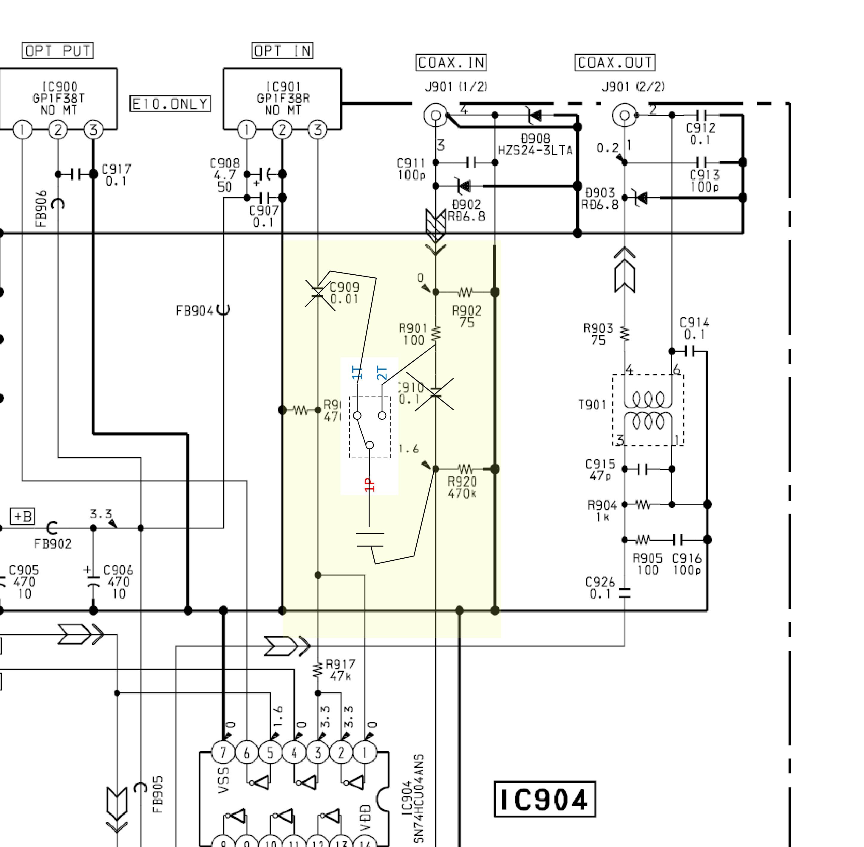
Mount the SPDT switch near the relevant components in the rear panel, I suggest removing C909 and C910 and installing a new 100 nF coupling capacitor where appropriate. The output can also be wired to IC904:13 instead of R920.
I used 1 ohm resistors for the ferrites.
All these components are on the top side of the PCB and silkscreen-labelled so it's fairly straight forward. I used a small PCB mount switch that fit snugly in a 4 mm hole with a bit of super glue, but this is up to you.
I also used a 3 pin 0.1" pin strip attached to the board with a small pigtail+female header coming off the switch, this is so I can get the main PCA out of the unit without desoldering anything.
Rear Panel Holes
You'll need to add some square holes where the optical I/O is on the main board. You'll probably want to use a file to get the holes square.
After fitting the square part of the transceivers, a simple transfer punch approach from the rear can be used to mark the mounting screw holes.
There's a metal support structure near the transceivers that give us some hole locations to reference off of, but unfortunately they're not precise. I suggest installing the new devices and marking them with a pen on the inside, then drilling + filing to finished size.
The center of the square is 10 mm below the mounting hole, and the extent of the square is 9.7x9.7 mm so a pre-drill of 8-10 mm is suitable depending on how brave you are. Use a stepped cone drill for this operation, twist drills do not work well with thin sheet metal and will likely damage the case.
Spacing between the two devices is 5 mm and conveniently they're also 10 mm from the bottom of the case. As expected the mounting hole is then 20 mm from the bottom of the case, centered on the hole.
If you installed a C14 inlet then you'll have two screws left over to hold the optical transceivers. Get M2.5 or M3 self tapping screws if you need new ones. M2.5 is slightly undersize but will work the first time (with the poor thread engagement it's likely to strip out after a few screwings.)
Some black enamel paint is also a nice touch after drilling to get rid of the shiny parts.
Obviously removing all the PCAs and drive to avoid damage is required, this is not a particularly difficult operation.
Other Ideas
The main MCU has an input labelled CD/MD connected to a jumper, the same pin is listed as SCMS ON/OFF in the pinout list for the same IC later in the manual.
JW303 is listed as installed at 47 kΩ in the Japanese model, while JW302 is listed as installed as 1 kΩ in all models (both chip resistors). Changing this around may do something to the SCMS support.
I checked if the similar vintage CDP-D11 used this board but it's quite different.
I don't particularly need to copy MD-MD and if I wanted to copy from a MD it would be to a computer that wouldn't care about SCMS but changing this around may have been useful to know about in 2001 or so. A SRC2496 can be used to clear this flag from the digital bit stream today if you really need to remove it.
Remote Control via PC
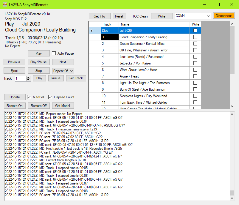
The E12 along with the E52 and E11 have a RS-232 serial port. Because Sony gotta Sony it's the wrong gender and you need a null-modem cable to connect it to a PC.
The documentation for the protocol is available online, and I've found one program that will actually use it (or attempt to use it, in any case): Sony MD Remote.
This program doesn't seem to be very robust nor very feature-filled, and communications are pretty spotty.
I just got a PS/2 keyboard and use that for track labelling instead. That stopped working, so I made a C# program to talk to it instead.
"Audiophile" upgrades
The balanced I/O provides excellent analog I/O, but I did note that the op-amp used in the balanced receiver wasn't super amazing by modern standards.
The original part was a Mitsubishi M5238P, a fairly old BiFET (JFET) op amp. SNR is pretty good but distortion performance can be slightly improved by replacing it with something like a OPA2134 or OPA1642.
This will improve the distortion performance from "not audible" to "not measurable", I did this mod while I was installing the optical receiver since I happened to have a couple of OPA2134s in DIP-8 laying around.
The balanced output chain uses NE5532s (strictly speaking Sony uses NJM5532s), these already offer distortion and noise performance well in excess off what most people need for this application so I don't consider it worthwhile to replace them.
The same BiFET opamp is also used in the unbalanced input chain, I didn't bother to replace that since I don't expect to ever use the unbalanced I/O.
You could also make the case that the headphone output circuitry is pretty mediocre; a pretty decent driver configuration is used on the main board (very low output impedance). However, it passes through a 1 kΩ pot and then 10 Ω damping resistors before going to the headphones, so the output impedance will be pretty high.
For the intended use (monitoring during recording), that's fine.
RTC Battery Replacement
This section added late 2023: I replaced the built in Li-Ion rechargeable battery with a new one, and found some caused directly by this.
The original battery was a Panasonic ML2020 3 V secondary cell, I replaced it with a VL2330 (same type as used in old PowerBook PRAM batteries, a strange coincidence). Replacement was fine, the VL2330 is a slightly higher voltage cell (nominal 3.3 V, vs. the 3 V of the original) but otherwise is likely to be fine. I saw some flux on the board indicating the battery I had in there may not have been original either.
After replacement the unit didn't start up properly, and eventually showed an IIC STOP error message.
This is not documented directly in the service manual, but this occurs due to a failure in communications between the main processor and the MD-mechanism controller IC, which uses I2C. The fix (for me, at least) is noted in the service manual:
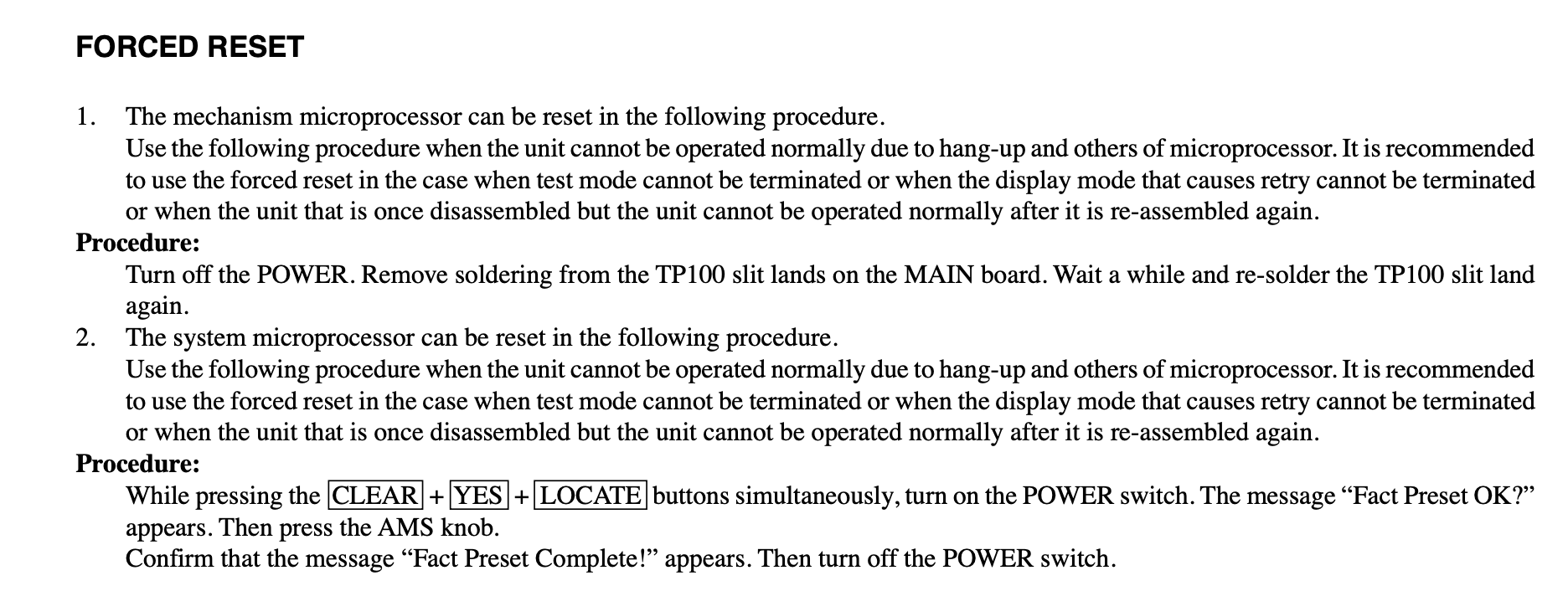
The key-press procedure didn't get to the complete message, but performing the TP100 desoldering trick (which is just disconnecting the battery) did work, and it reinitialised correctly and played successfully afterwards. I also saw flux remains on TP100, suggesting this was an issue last time it was replaced.
It seems these units have a surprising amount of circuitry hanging off the backup battery (may be wise to hack in an even larger battery for intermittent use). One of these things is the MD-interface processor on the main board, which may not start up properly when the battery is swapped. I'm surprised it hasn't had issues with battery drain, given I found the battery at around 1.5 V when I pulled the unit out again.
