Adapting 150 Ω Microphones to Electret Radios

After some time with my modified Comtac-a-like Sporttac setup, I found a good deal on a few proper noise reducing 150 Ω dynamic microphones. In order to use them, I had to modify my setup a bit.
Table of Contents
In my case I found a good price on some Peltor MT31 microphones with the cords cut off. All these dynamic microphones appear to be very similar in specifications, and the MT31 is largely identical to the MT33 and MT73, as well as the non-IP68 rated MT7N.
The benefit of a dynamic microphone is primarily that these microphones have a more directional design by using a larger membrane than an electret type. This directionality combined with the recommended 3-5 mm distance from the mouth makes them well suited to extremely noisy environments (this type of microphone is used e.g. by air force ground crews near jet engines).
You do actually need to push these mics into your lips to get good sound, this is how the noise reduction works. Also note that the microphones are directional, so you have to talk into the side with the arrow.
The key specification is that these are dynamic microphones with a sensitivity of around -66 dBV⁄Pa. This not very high, equivalent to 0.5 mVRMS per Pascal of applied sound pressure, a typical electret is specified as around –42 dBV⁄Pa, or around 8 mVRMS. This means that our nominal amplifier voltage gain should be around 16⨉.
I noted that the dynamic mic RMS output when blowing into it (with a foam wind-stopper) could reach 8-5 mVRMS, while speech tended to sit around 0.5-1 mVRMS. This tells us that a close talk microphone is typically subject to around 1-2 Pa of sound pressure, but can peak at 10-20 Pa.
Further, dynamic mics are 150 Ω nominal impedance, while electret microphones are typically supplied through 2 kΩ with a bias voltage applied for the internal JFET amplifier.
In order to match the signal levels and impedance, you could possibly use a transformer, but this is often too bulky to be practical for a portable setup.
The output energy for the 150 Ω/0.5 mVRMS case is around 1.6 nWRMS, while the electret output is around 32 nWRMS (2 kΩ/8 mVRMS). This is a ratio of ~20⨉, and this indicates that a transformer is not suitable in this case, and amplification is needed.
This follows since it's not simply an issue of the microphone energy being at the wrong impedance, but rather even with an ideal impedance converter from 150 Ω to 2000 Ω, the dynamic microphone produces 1⁄20 the energy of the electret.
The Amplifier
I chose to use a transistor amplifier, which I built into the PTT-box. This way the amplifier is also matched to the specific device the PTT is wired for, allowing me to tweak the design to match specific device in case a generic solution is not workable.
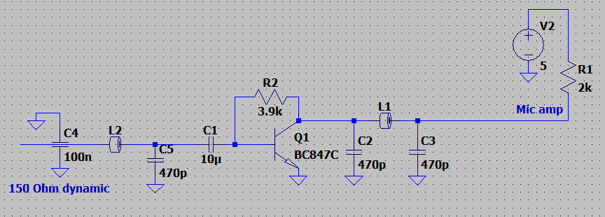
The design for the amplifier is quite simple, being optimized for small component count, and keeping in mind that the maximum output voltage will be around 100 mVp-p.
I will note that this amplifier has a 0 Ω input impedance (ideally). In my testing so far this hasn't been an issue. Some microphones may not have an acceptable frequency response when terminated to 0 Ω instead of their specified 150-200 Ω impedance (microphones are often also designed for termination into 10⨉ their impedance), and in this case I suggest adding a suitable series resistor to the amplifier input.
Further it's worth commenting that this amplifier is essentially a transimpedance amplifier, that is it shorts out the input and converts the input current to an output voltage with the gain set by R2. This could potentially cause changes to frequency response, since the frequency response is now set by the frequency-variable source impedance of the microphone. A similar effect occurs in speakers, which is why voltage-mode amplifiers are used.
The classic BC847C is a low cost and decent audio amplifier with adequately low noise levels and high gain. You could use other transistors for the job, though the 2N2222A and 2N3904 are probably best avoided for audio amplification.
If you want to use something else, consider that we need a very high hFE at a 1-2 mA operating current, the 2N5088 (MMBT5088) is probably a good choice, since it's better specified for noise figure in various conditions.
This amplifier is powered through the standard microphone bias resistor inside the radio, which is typically 2-5 V through a 2-4.7 kΩ resistor. The amplifier circuit as built gives less than 2% distortion (often below 1%) with a usable bias voltage range (open circuit) from around 1.5-6 V.
The voltage gain with a 150 Ω series resistor at the input is around 15-20⨉, being somewhat dependent on the applied bias voltage (probably due to the operating current and hFE relation). The amplifier is AC coupled, and self biasing with a single feedback resistor from collector to base, this resistor also sets the gain in relation to the microphone impedance. Due to the single-resistor feedback biasing, the collector voltage will be kept at around 600 mV, this is acceptable for very low level signals but does limit the maximum output voltage swing by a lot. The upside is that the bias voltage provided by the radio is not critical, and anything between ~1.5 to 5 V works fine.
Since the design uses a bipolar amplifier, it is sensitive to RFI from the radio transmitter, in particular DMR radios can cause nasty interference due to the TDMA system. In order to avoid this, the input to the amplifier is fed through a 100 nF feed-through capacitor soldered to the PCB, there is also a small ferrite bead and a 470 pF decoupling capacitor on the input. This effects a basic π-filter on the input, with the feed-through handling the bulk of the bypassing.
The output is also routed through a π-filter, due to the higher impedance we can't use a nice 100 nF feed-through cap. 1-10 nF total bypass capacitance is acceptable for most use-cases.
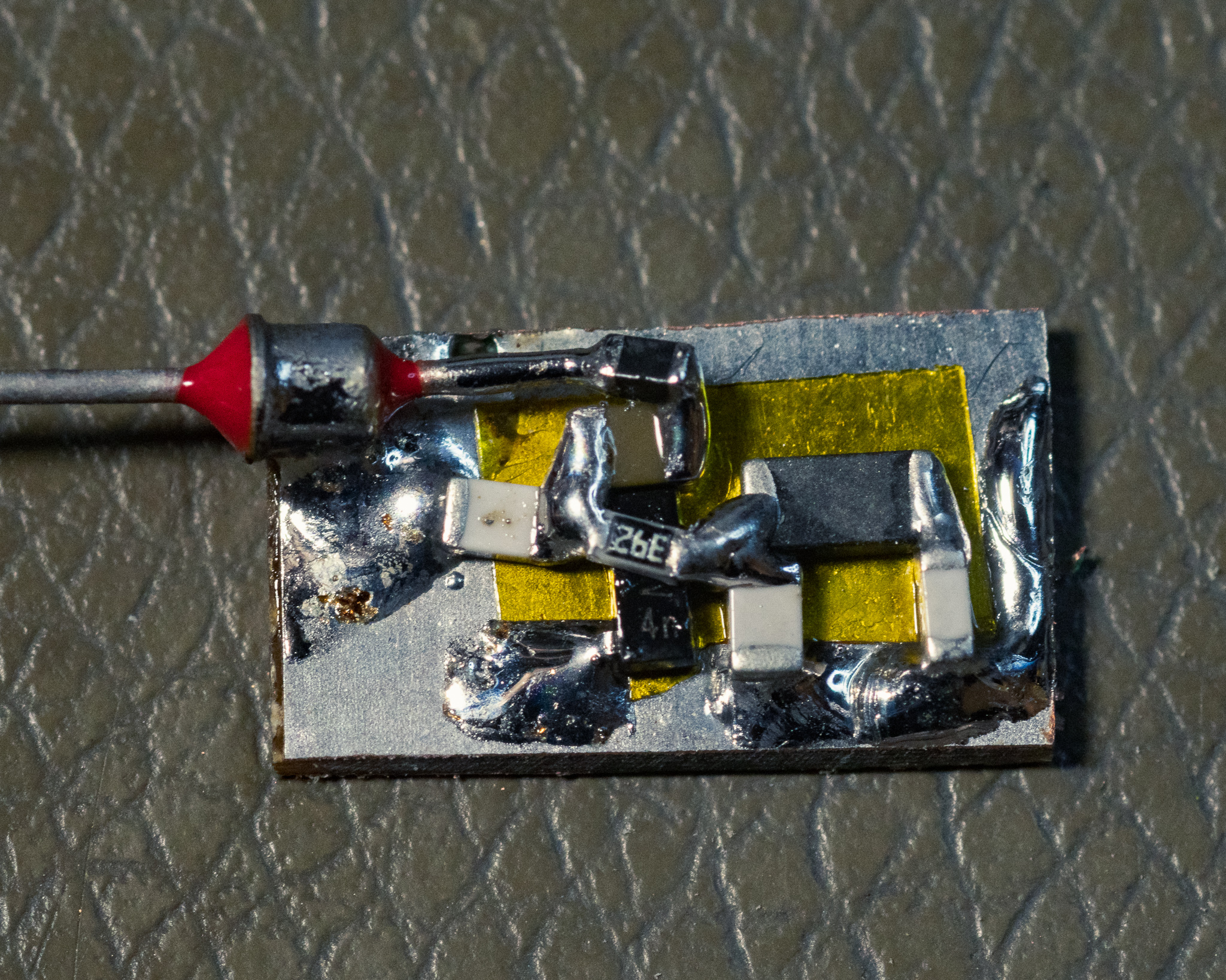
As built I found that this system is seemingly completely insensitive to 5 W VHF and UHF (DMR & FM) hand held radios with the antenna pushed right into the amplifier and unshielded wiring. I will note that doing this as an SMD amp on a ground plane makes it inherently less sensitive to RFI compared to a through hole version.
Keeping it compact (smaller than 1⨉2 cm) makes it easy to fit in the standard eBay style PTT adapters, that have a fair amount of free space near the PTT switch.
As an aside, using a MOSFET amplifier is inherently more insensitive to RFI, the issue I found is that a typical e.g. 2N7002 NMOS transistor has far too little voltage gain at these operating currents, and it ends up operating in open-loop. Due to this it also ends up being far less linear, struggling to hit 4% distortion in cases where the bipolar can do sub 1%. Most FETs also require around 2-5 V for the gate-voltage, limiting the usable voltage range, though a FET amplifier might be practical with a modern low-gate threshold FET with a high transconductance.
You could get away with using a small opamp in here, a CMOS 1.8 V rated type could work, but there also seems to be little benefit to doing so. An opamp will typically be noisier than a single transistor solution, though distortion will likely be lower.
Verification
I tested the circuit with the following radios, using eBay sourced PTT wiring:
- Motorola DP4600e (i.e. XPR7500 series)
No issues in FM or DMR. 5 V bias through around 4.7 kΩ bias.
- Motorola GP3x0
5 V bias through a 2 kΩ resistor.
Works fine.
- Motorola GM360
Requires additional amplification, schematics list a nominal 80 mVRMS microphone signal and a 9 V/560 Ω biasing scheme.
Motorola hand microphones are amplified, so you need to build an additional amplifier similar to the standard hand microphone to make it work right.
This amplifier provides a voltage gain of around 10 when driven by a 2 kΩ impedance source and 560 Ω collector loading. This is consistent with the expected levels at 1 Pa sound pressure, where a typical electret outputs around 8 mVRMS, and the radio schematics list 80 mVRMS signal levels.
I built the core transistor amplifier circuit with a BC847C and performance seemed adequate when hooked up to the standard dynamic-electret amplifier.
Q1303 drives the PTT when the mic-bias is applied through SW1301 in the Motorola design; this appears to be done to ensure that there's no hot microphone unless the PTT button is pushed. This is usually not a problem for ham radio use and the documentation implies this is a security feature.
You can use handset audio output on pin 8 to drive a headset, though volume may not be optimal. Handset audio output requires an AC decoupling capacitor of e.g. 100 µF to work. Since the RJ45 plug has power available you could also use this to power amplifiers for both the microphone and speaker if desired.
Note that the RJ45 plug is wired backwards compared to e.g. telecom standard, so pin 8 is towards the left side of the radio as viewed from the front.
| Pin no. | Name | Notes |
| 1 | FLT_A+ |
~12 V unswitched, 22 Ω 0.125 W in series Max current ~60 mA due to 22 Ω/0603 series resistor |
| 4 | GROUND | - |
| 5 | MIC | 80 mVRMS, 9.3 V/ 560 Ω bias |
| 6 | PTT_IRDECODER | Ground to PTT |
| 7 | BUS+ | Pulling current here locks up the radio, do not use |
| 8 | HANDSET_AUDIO | DC biased, level fixed relative to speaker, noisy when not receiving |
- Icom IC-T70
Not verified yet, but should work.
- Hytera MD785
Not tested yet, but service manual indicates an 80 mVRMS microphone level, 5 V power available if accessory ID bits set correctly. Similar design to the GM360 should work.
This radio will be covered in a separate article with a more complex design.
- iPhone 12 through Apple Lightning adapter
Works fine, including mic-button.
Addendum: Operational Amplifier Solution
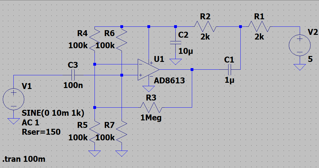
We can make a more "proper" solution possibly with better performance (likely better distortion, worse noise) by using a modern operational amplifier.
If we decide we want a SNR of 30 dB or better over the typical 5 kHz bandwidth we care about and the reference level is 0.5 mVRMS, then we need an output noise floor (referenced to 1 kHz) of 16 µVRMS. Since we want a gain of approximately 20⨉, the total input referred noise floor must be 16 µVRMS⁄20 = 0.8 µVRMS. Since the 150 Ω microphone element is considered to be a low impedance source, we care more about voltage noise than current noise, since this will dominate the noise contribution.
By assuming a flat noise floor spectrum (i.e. assuming 1⁄f noise is irrelevant and gain bandwidth is high), this means the opamp + resistor noise contribution needs to be at around 12 nV⁄√Hz. We may have to compromise vs. power consumption, so let's say we need it to be below 30 nV⁄√Hz, and lower is better. A typical single transistor amplifier will be in the 1-4 nV range.
We also need an opamp with very low quiescent current, high PSRR, operating voltage up to 5 V, and ideally down to 2 V or less. We also will require it to be a CMOS type, though this is a de facto requirements given the voltage range and quiescent current we want.
The AD8613 and OP313 are suitable options here, you may be able to accept a higher quiescent current to achieve even lower noise and higher gain bandwidth. With a noise floor of ~20 nV⁄√Hz these will give an acceptable 24 dB SNR.
I haven't bothered to do a full noise analysis of the above circuit, but key to achieving good performance is balancing the feedback resistor thermal noise with power consumption and component size. For example, the above example will be noise limited by the feedback resistors, so you could use a much noisier opamp without any real impact.

The above circuit will likely be better, we achieve DC bias using the largest feasible value, then AC bypass it with the largest capacitor we can.
R7 does not contribute noise since it's in parallel with the microphone element, and the resistive noise from R3 and R6 is significantly lower due to the lowered impedance.
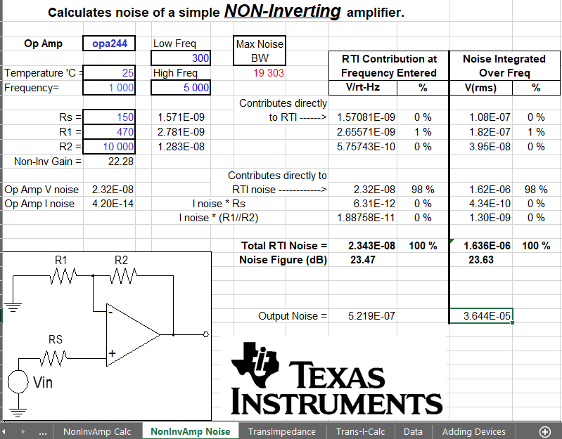
Texas Instruments provides a fairly old spreadsheet to do these calculations here: OPAMP-NOISECALC.
Using this tool and the similar OPA244 as the opamp, we can calculate that the first solution will give an input referred noise of 2.5 µVRMS (~52 µVRMS output), and the improved variant will give an input referred noise of 1.6 µVRMS (~36 µVRMS output).
The improved circuit is entirely limited by the opamps voltage noise floor, with 98% of the noise coming from the amplifier itself. In practice you can therefore increase the feedback resistor impedance a fair bit to reduce power consumption without any significant noise floor impact.
Obviously a practical circuit will also require RFI protection, though this can likely be done with a basic ferrite/capacitor filter on the inputs and outputs. The use of a CMOS amplifier reduces the base sensitivity to RFI a lot.
Add a suitable capacitor in parallel with R3 to roll off the gain at a suitable frequency (5-10 kHz range) to keep it happy. Adjust R2/C2 to match your devices operating current and; higher R2 value is better for power consumption but may drop the supply voltage too much.
The TLV316 appears to be a sweet spot, in the above circuit the OPA316/TLV316 with 47 kΩ/3.3 kΩ feedback will give a input referred noise floor around 1 µVRMS. Anything better than this for noise will also require more current, e.g. the OPA320 would be even better for noise but doubles the operating current.
I will likely get back to this topic at a future date, as I am planning on doing a flex-PCB for this purpose.
Noise Figure, vs. Bipolar Amp
The proposed opamp circuit has a noise figure vs. a 150 Ω source of around 24 dB, while the best practical circuit is likely around 13 dB.
A BC847C for comparison has a specified noise figure of 2-10 dB (quite a wide variation), with an impedance of 2 kΩ (at 100 µA collector current). This is equivalent to an input referred voltage noise density of around 5 nV⁄√Hz for the optimal case, and in the 150 Ω system this is a noise figure of 10 dB or so.
So we see that the BC847C based amplifier to a first order can match or surpass the opamp solutions, but the opamps are likely to be more consistent since opamp noise is usually a maximum specification, while the transistor is a max + a typical.
The MMBT5088 figures are in the same range as the BC847C, but it has a more complete specification including these plots:
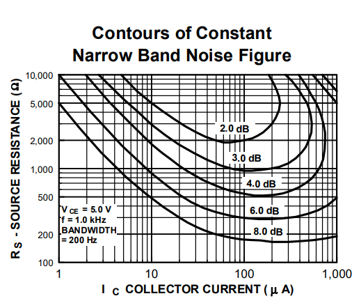
The above chart can be confusing, but what it's telling us is that at a center frequency of 1 kHz (measured in a 200 Hz bandwidth, but this is not relevant): If we want to achieve a noise figure of e.g. 3 dB with a source impedance of 2 kΩ (Y-axis), we will get this as long as we keep the collector current between ~20-500 µA (X-axis). The optimal range for this case is around 70-100 µA where the noise figure approaches 2 dB.
We can see that in our case there is no way we're getting below around 8 dB for a 150 Ω source impedance.
This is essentially providing the same data as the opamps noise-voltage and noise-current density plots, but in a more confusing and usually less detailed way.
Achieving Optimal Performance
The only realistic way to improve the system noise figure to below ~10 dB would be to use an impedance matching transformer between the microphone and amplifier to transform the 150 Ω source to a higher impedance. This is typically not feasible for a portable application due to the size of the transformer, but may be viable for a mobile or fixed installation.
One available transformer option is a 150:40 kΩ transformer, which would need to be followed by a FET input (or CMOS) opamp (if you go to e.g. 2 kΩ you could use a bipolar amplifier, but above this a CMOS opamp will likely have better noise performance).
Note that center tapped 600 Ω transformers are 150 Ω if you only drive one half of the winding. As such another available option is 600CT:50k (or 30k).
With a 40 kΩ source impedance the noise figure with a 10 nV⁄√Hz CMOS opamp would be in the 1-2 dB range.
Note that transformers are not completely noiseless, the transformer winding resistance will contribute resistive thermal noise just like any resistor. The benefit is that the winding resistance of a transformer is usually much lower than the AC impedance. As such one quality factor of a preamp-transformer is the DC resistance, especially on the low-impedance primary side.
This will be covered in a future post, once I have the required transformers and new suitable PCBs for this purpose.
Addendum: Handsets
Military handsets are another option compared to headsets, these are typically more practical for general purpose use, and are a decent upgrade from a hand-microphone. One nice feature of a handset is that the mouth-mic distance is fairly fixed, as well as some noise reduction on receive due to the handset speaker blocking external sound.
The H-189/GR and H-250 handsets are fairly common, and the H-350 is a less common option (this is a full duplex variant with a separately wired hot-mic). The H-189/GR is a non-noise reducing microphone type, while the H-250/350 provide acoustic noise reduction.
In my opinion the H-250/350 are technically better handsets, while the H-189 is heavier and more solid feeling.
These handsets are fairly well documented as far as wiring, colour codes etc. go.
H-189/GR is specified in MIL-H-55258B and characterised in AD0295832, while the H-250 is specified by MIL-PRF-49078A.
Speaker
The speaker in these is 1000 Ω, and can be driven by a standard audio-opamp; the sensitivity may be a little low if connected to a typical 8-32 Ω speaker driver since these need more voltage.
You could also use an audio transformer for the speaker; something like a 8:1300 Ω ("EE14") transformer normally used to interface e.g. small tube amplifiers would give a good power match, though you may want to add a resistive attenuator as well since it will likely get uncomfortably loud.
Maximum permissible speaker power is 300 mW (no damage, to the speaker, not to your ears).
Microphone
The sensitivity of both the H-250 and H-189/GR is listed as minimum –56 dBm at 28 dyn⁄cm², or Watts⁄Dyne⁄cm², this is considered a somewhat obsolete unit of measure. Most modern specifications use dBV/Pa as the base unit. The Dyne unit is part of the centimetre-gram-second (CGS) measurement system while most of the world uses the metre-kilogram-second (MKS) system.
As a favour to y'all I've tried to convert this into a common V⁄Pa measure by changing the units around:
28 dyn⁄cm² is equal to 2.8 Pa, so it's now –56 dBm⁄2.8 Pa, and –56 dBm is 2.5 nW, equal to 0.61 mV by Ohm's law in a 150 Ω system impedance.
The sensitivity is then 0.61 mV⁄2.8 Pa which is equal to 0.2 mV⁄Pa, and we can also calculate the standard measure –73 dBV⁄Pa for a resistive 150 Ω termination.
In practice we can add 6 dB to this voltage sensitivity if the microphone is not terminated into the system impedance, but rather into a high input impedance amplifier such as a non-inverting opamp. If we assume the boom-mic voltage level specifications are for an unloaded microphone (which is the common case in modern equipment), then we find a specification of –67 dBV⁄Pa, which is the same as the boom-microphones we started with.
The 3M/Peltor boom mics are specified as –66 ±4 dB tolerance, while the handsets are specified as –67 –0/+6 dB.
You can reasonably amplify the microphone output using a low noise audio opamp like the NE5532, for the GM 360 (80 mV signal) I found two amplifier stages to be suitable.