Macintosh IIfx Astec Power Supply
This is an overview of my efforts to re-cap and fix a connector issue with the Macintosh IIfx Astec manufactured power supply.
Table of Contents
Introduction
The Macintosh IIfx is a high performance 68030 based Mac II system with several NuBus option card connectors. This combination makes it a pretty hungry boi.
From what I've seen online most/many IIfx's come with a Sony power supply.
My IIfx came with an Astec AA13780 (or perhaps AAI3780, hard to say). Apple part number 699-0389. It looks to be a 1988 vintage, made in Hong Kong.
It came with a very loud fan, I replaced it with an 80 mm Noctua fan. There is an internal 12 V header that powers the fan. In theory this is supposed to be speed controlled, it kind of works.
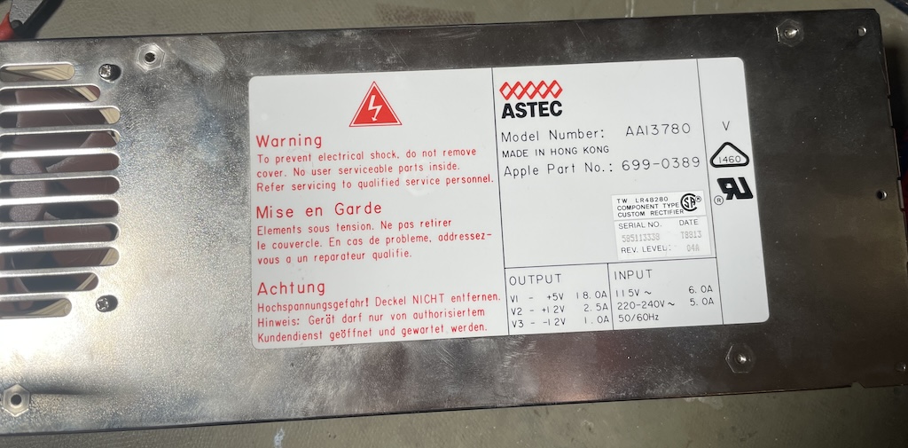
The ratings are shown above, note the high 18 A rating on the +5 V rail. Some old forum posts suggest these ratings are average power, with an even higher peak current rating.
After some months in operation the computer started shutting off randomly some time between 15 and 60 minutes. Around this time I had temporarily lost interest, so I put the machine away for a few years.
The TFX Replacement, Thoughts
Digging it out now, I had intended to perform a TXF power supply replacement, as documented here: Macintosh II(fx) Modern Power Supply Replacement.
I acquired the Inter-Tech power supply specified, but upon taking a closer look at my existing power supply issues I became concerned about the safety of this modification.
The TFX supply used is only rated for 15 A on the 5 V rail, and it is likely that overloading of the –12 V rail will occur as well. Note that many computer power supplies do not monitor the –12 V rail and will die randomly if this is overloaded.
I was also concerned with the very thin wire cross sections used by the TFX power supply compared to the original which used AWG 18 (approximately 1 mm²).
Additionally I have comments on the choice of crimp pins, the cheapest standard pins are likely to cause issues in the long run (the linked article doesn't specify exactly pins to purchase).
I appreciate the work the original author of the TFX modification did, and the 3D prints provided worked well. However, I would not recommend this modification be performed unless absolutely necessary.
I recommend the following checks be performed when performing that modification:
- Ensure the power supply can supply minimum 15 A continuously, or measure actual load current.
- Ensure AWG 18 or 20 hookup wire is used for 5 V and ground returns (may involve replacing the pre-attached wires).
- Use Trifurcon contacts for the new connector (see later section of this article).
- If the existing PSU connector has signs of overheating, replace the motherboard header before proceeding.
- Measure –12 V current draw in system, if the draw exceeds 0.3 A then you'll need to generate the –12 V using a DC/DC converter powered from e.g. the +12 V rail.
- Consider fusing the +12 V supply; if a short were to occur in the machine (e.g. in the hard drive) there is a real risk of vaporising the motherboard traces since they will only be rated for the original supply's current limits.
I instead elected to repair the existing power supply, despite having the required parts to perform the TFX swap.
Astec Issues
To get my Astec supply up and running I did two things, first was a replacement of all electrolytic capacitors. Second, I replaced the DC output harness along with the connector to the motherboard.
The power supply is generally quite well built and my unit was in good shape overall.
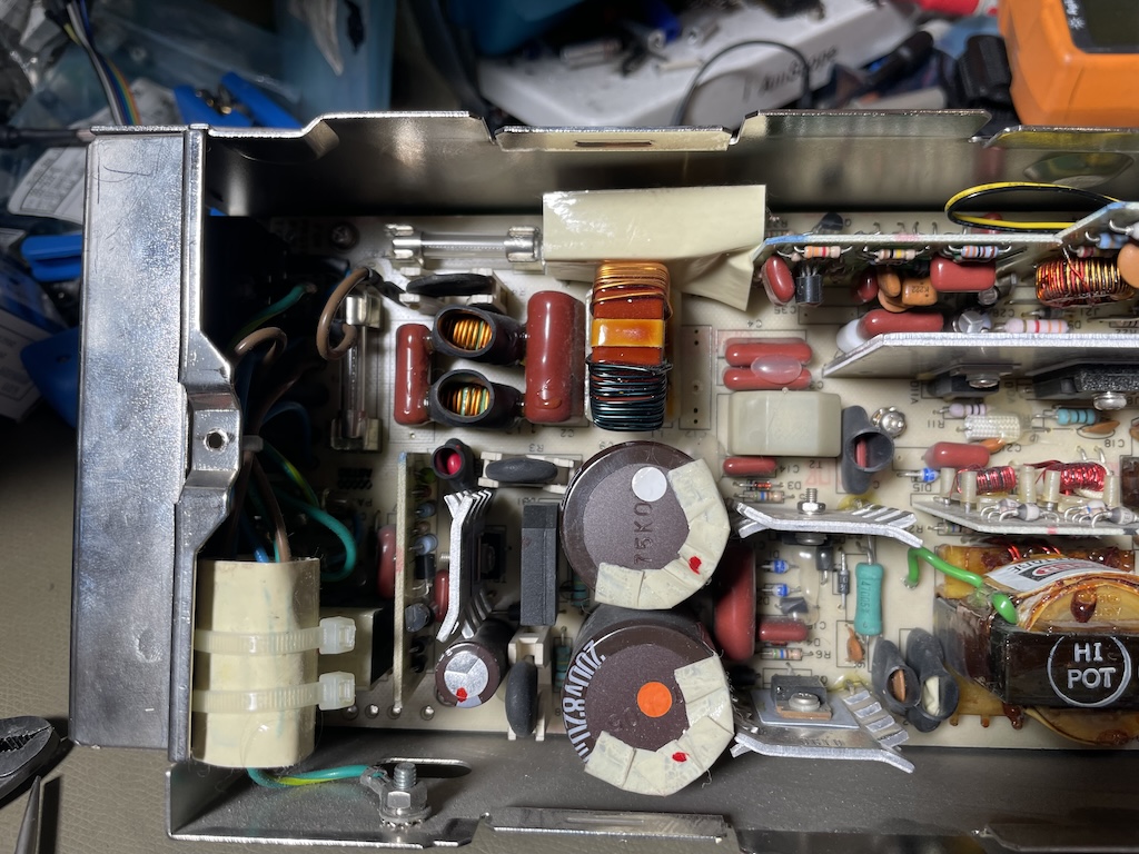
Electrolytic Capacitor Replacement
Since I couldn't find a capacitor list for this model, I made one myself and ordered the required capacitors off Digi-Key, I chose to use all 105 °C long-life capacitors from Chemicon or Rubycon.
After removal I checked the capacitance and impedance of all the capacitors, and found no obviously bad units. C23, C28 and C306 did seem to be fairly mediocre with high ESR and reduced capacitance. These two were coincidentally the only 85 °C rated capacitors in the power supply.
The replacement parts I ordered and their reference designators are shown below.
| New Part Number | Pcs. | Reference Designator | Rating | Comment |
| EKYB160ELL222MJ30S | 2 | C5, C22 | 16 V, 2200 µF | |
| LGR2D821MELB40 | 2 | C9, C10 | 200 V, 820 µF | Difficult to replace |
| 50YXM22MEFRT15X11 | 1 | C23, C28 | 25 V, 22 µF | C23 near +12 V output |
| EKYB101ELL270MHB5D | 1 | C17 | 100 V, 22 µF | |
| EKYB350ELL271MH15D | 2 | C310/C311 | 25 V, 220 µF | |
| ELE-500ELL3R3ME11D | 1 | C306 | 50 V, 2.2 µF | |
| EKYB350ELL332MLN3S | 2 | C20, C22 | 35 V, 2200 µF | |
| EKYB350ELL222MK35S | 1 | C26 | 16 V, 2200 µF |
I found C9 and C10 to be difficult to replace and I don't recommend replacing them unless necessary. The other capacitors were relatively easy to remove with a simple Jonard solder pump (highly recommended). As mentioned above all the Chemicon 105 °C capacitors measured fine in my unit. C23, C28, and C306 were 85 °C rated, and readings were suspect, having a higher than expected ESR.
I also did a once-over with flux and solder to check all the joints in the supply, I found no signs of bad joints, though a handful of leads seemed to have had sub-standard solderability when originally manufactured.
Also note that these models contain Rifa capacitors which are prone to smelly failure. Capacitor C13 should be replaced with a 22 nF 250 V X2 class film capacitor, it can be temporarily removed without functional issues.
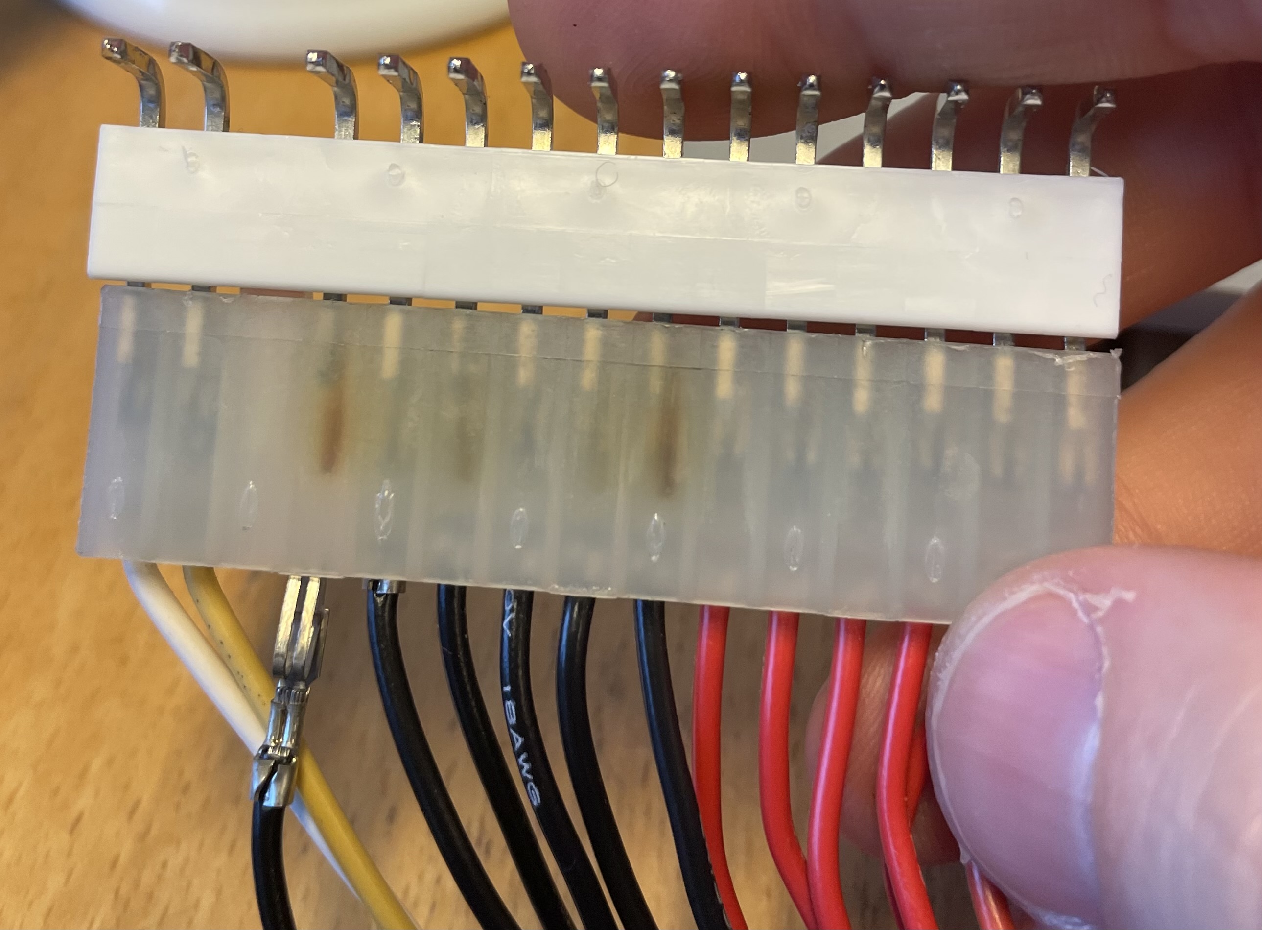
Wiring Harness Issues
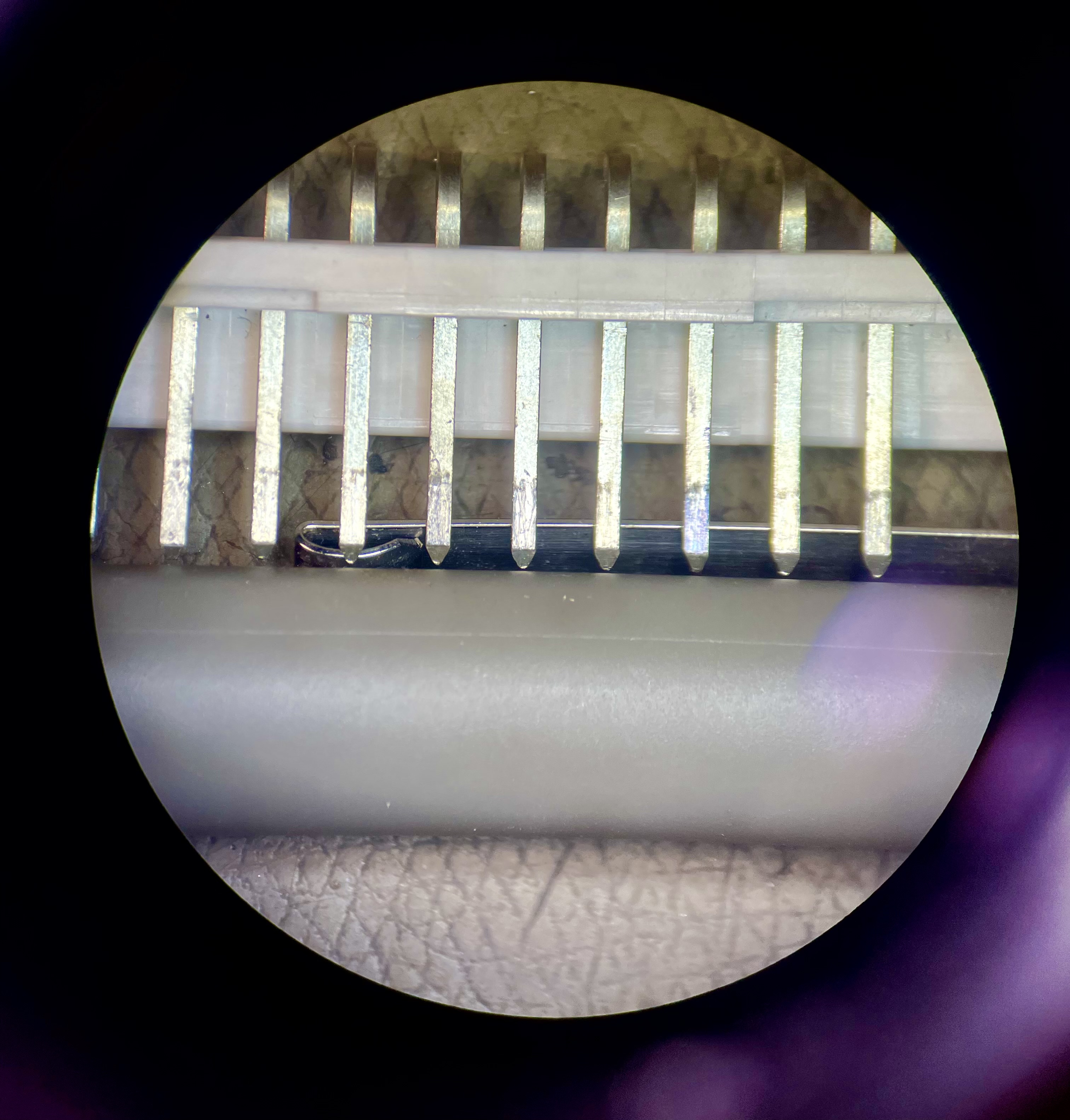
Upon removing the supply (intent on doing the TFX conversion) I found some concerning burn-marks on several of the ground return pins:
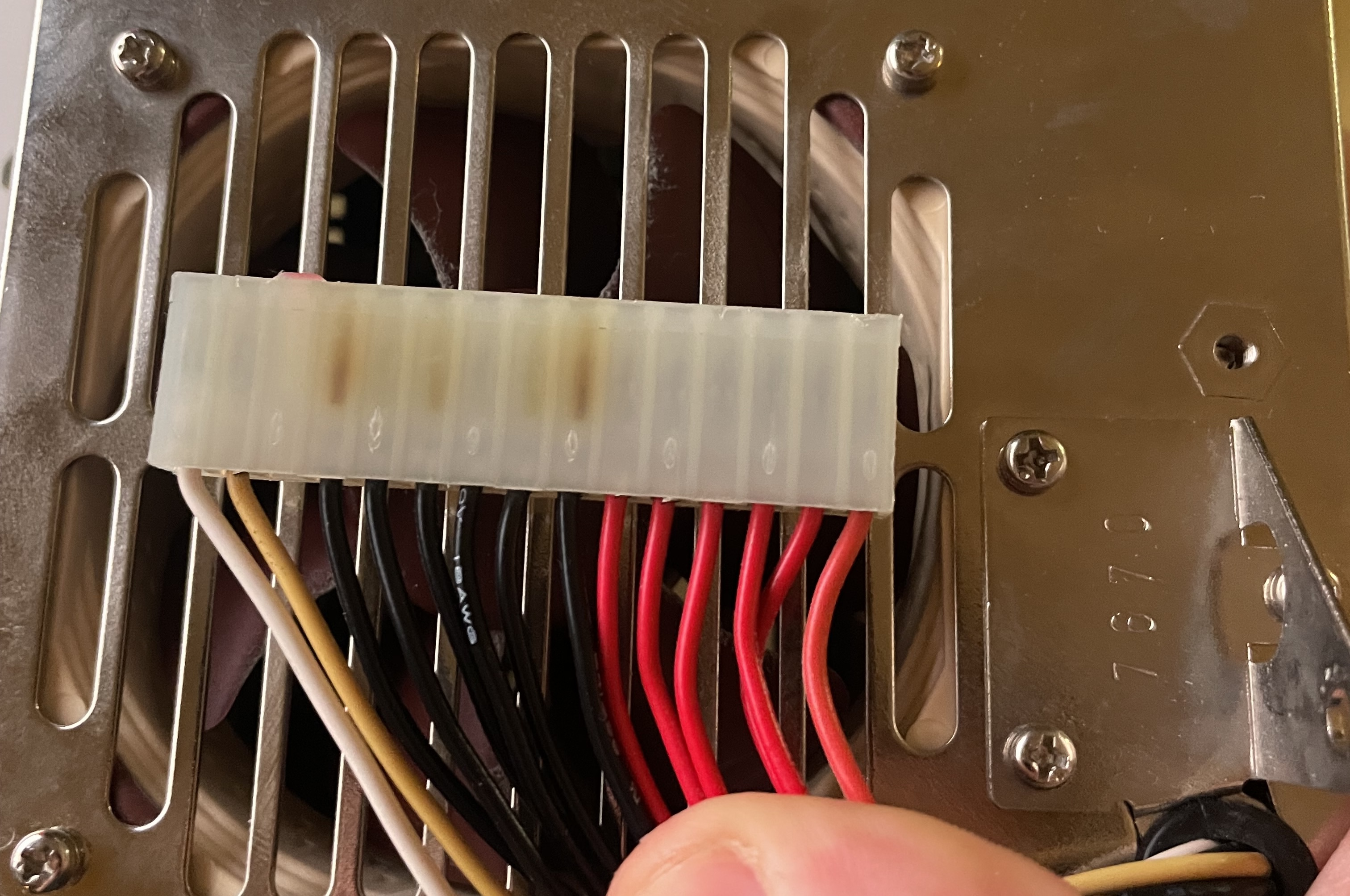
Seeing this I realised it was sus, and this could well be the cause of the random shutdowns. The burns are not visible when the supply is installed in the machine, since they are on the bottom of the connector.
I decided to attempt to replace the cabling along with the electrolytics.
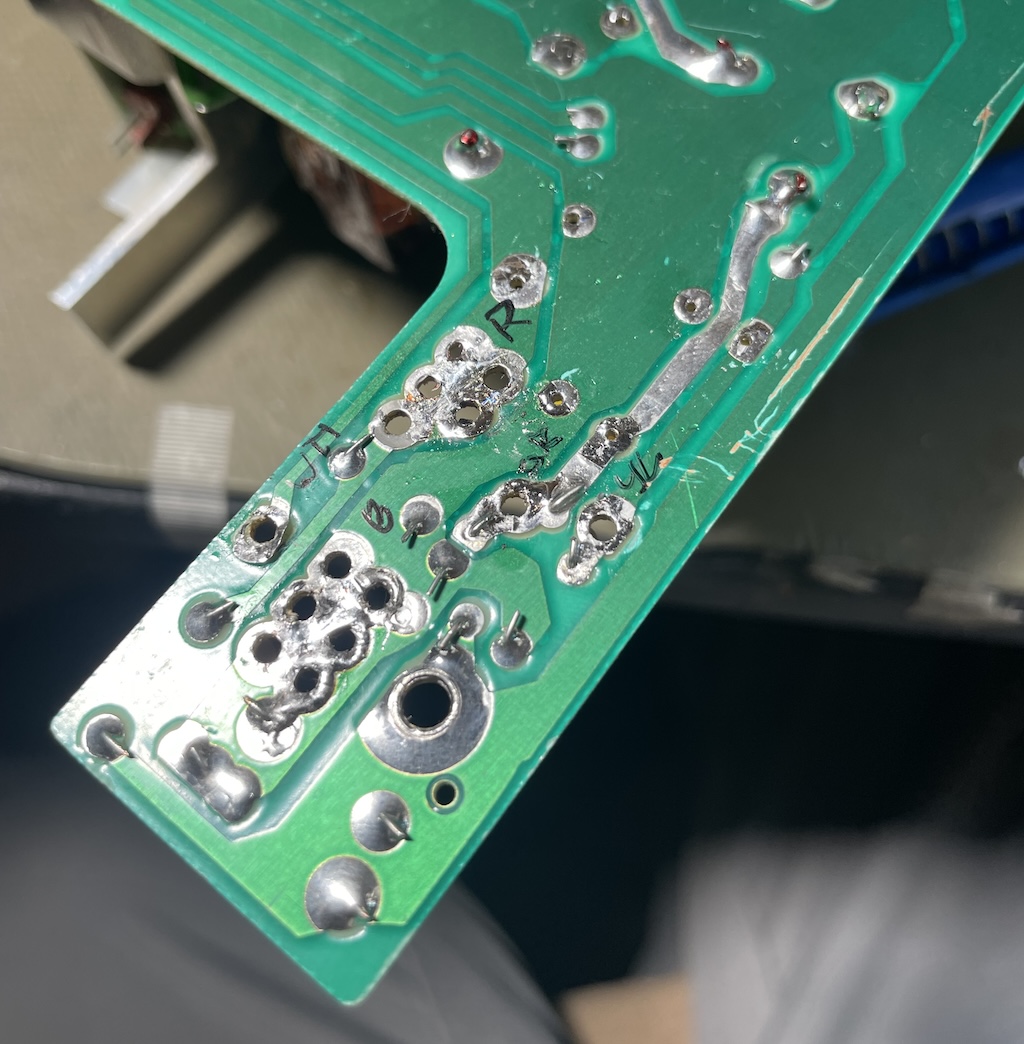
A root-cause analysis was performed on the original cable and motherboard pin header, and both were removed.
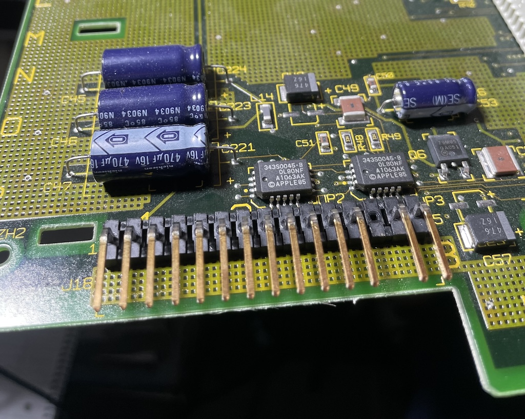
The above picture shows the pin header on the motherboard after removal (relatively easily removed with a good Jonard solder pump). It does not look obviously defective aside from one pin which has a bluish (thin film interference type) contamination on it. There is little difference between the burnt and un-burnt pins otherwise. The motherboard header must be replaced along with the cable harness if this occurs to avoid future problems though.
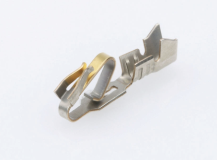
Above I pulled out one of the more burnt terminals, and found no significant issues there either, rather worryingly each individual component looks mostly fine!
Note the special terminal design with a double spring presumably intent on making two points of contact. The standard KK .156" series terminals only use a single large spring here, and I believe this rather flawed modification is intended for higher current applications.
The per-contact current can approach 4 A which is likely very near or at the limit for standard terminals. If a single pin goes bad then the remaining pins will see an increased current and burn out as well.
This double contact design doesn't appear to be sold anymore, likely for good reason. In the picture above you can make out that the burn marks are distinctly lop-sided, suggesting that the right side springs burnt. The contact housing holes are far too wide for this contact to work as you can easily insert it off-center and in that case only one of the two springs will make a good connection.
If you have a Mac II with this style of power supply, make sure to center the connector when mating to avoid these issues. The plastic shells can be used to aid alignment, they seem to be well centered.
Power Supply Connector Replacement
I did some looking around and found that the standard cheapest contacts for this connector series are likely very marginal for the amount of current a fully loaded IIfx will pull.
There is an upgraded series of contacts that fit the same shell called "Trifurcon," and the phosphor bronze material option is rated at 7 A nominal (5 A with cheaper brass terminals). This is accomplished by using two side-springs which give increased surface area, a much better design than the old fork-spring.
I also went with gold plated contacts, I don't think this matters for high current applications, but I don't think it has any major downsides.
I additionally bought a new plug housing, a pin header for the motherboard, new coloured wires and a keying plug. The part numbers are listed below for my replacement.
| Purpose | MFG | MPN | Comment |
| IIfx Header | Molex | 26482152 | Right angle 0.156" 15-way, gold plated |
| PSU Cable Shell | Molex | 9503151 | |
| PSU Cable Keying-pin | Molex | 15040219 | |
| PSU Cable Pins AWG 18-20 | Molex | 8580111 | Trifurcon, bulk package, gold, phosphor bronze, $$$ |
| Hookup wires AWG 18 | Tensility Corp | 30-01733 et al. | Part number for black, series contains all required colours |
I would also strongly recommend anyone making a new cable for e.g. a TFX or ATX conversion use the pins specified above, and to replace the motherboard pin header if any signs of overheating are observed. If the cables coming from your replacement power supply are smaller than AWG 20 then you're playing with fire.
And make sure to buy bulk (loose) pins, not ones on a belt. The belt mounted pins are are very annoying to deal with.
Pinouts & Testing
The colour codes and pinout is:
Pin 1, Orange, +12 V, Pins 2-6, Red, +5 V, Pins 7-12, Black, Ground return (isolated), Pin 13 is plugged, Pin 14, Yellow, –12 V, Pin 15, White, On/Off.
To power it on standalone, apply more than around 3-4 V to the white pin relative to ground.
The minimum loading is apparently 3 A on the +5 V rail, and 20 mA on the ±12 V rails. A 1.5 Ω resistor rated minimum 25 W and two 560 Ω 0.5 W resistors should be sufficient for testing the power supply operation.
Photos
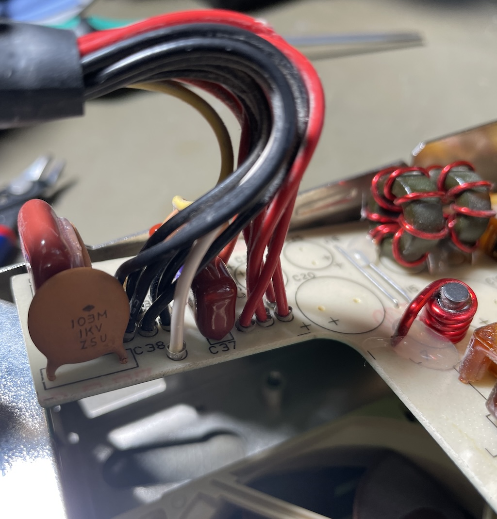
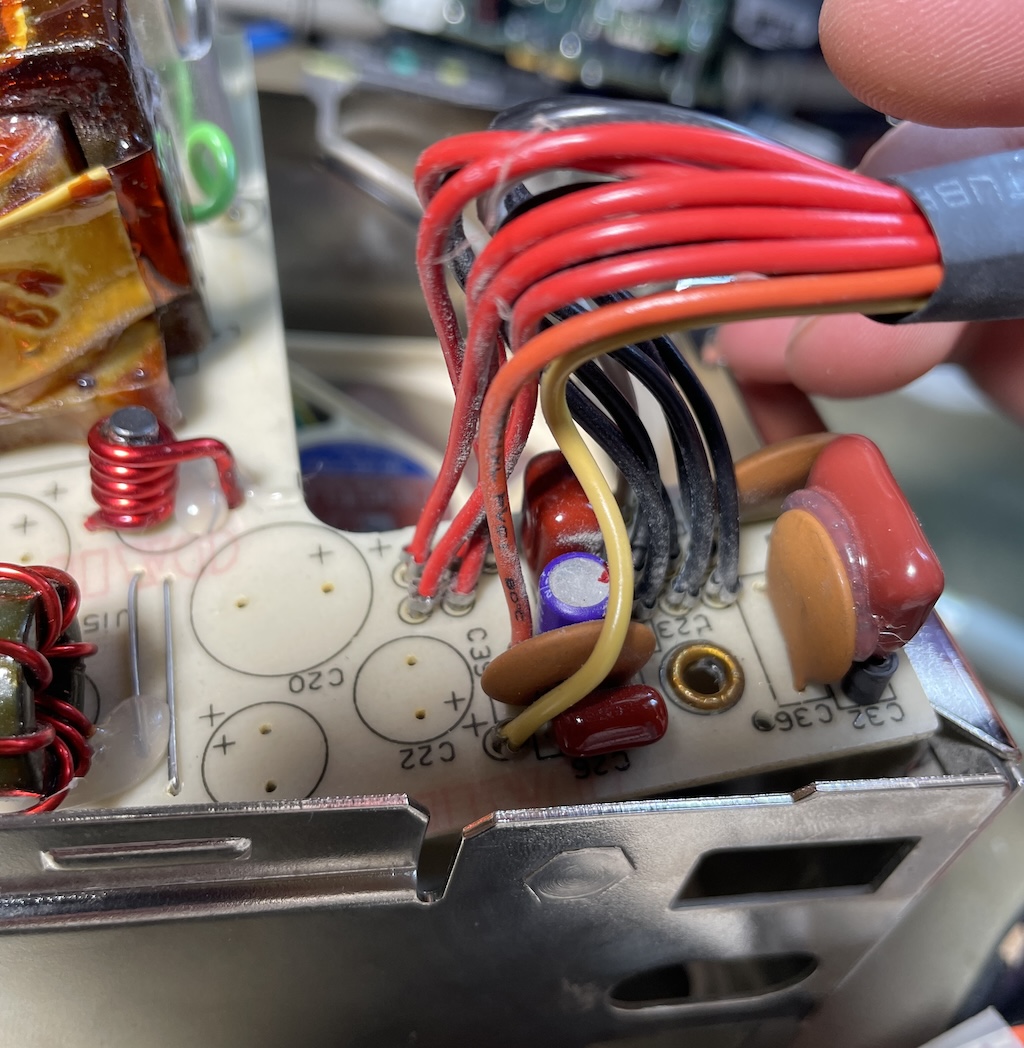
Below are some photos of the power supply connection points and motherboard pins useful for creating a new harness.
For the new harness I installed crimp-on ferrules on the AWG 18 wiring and soldered in place. The harness is pretty short so try to resist the temptation to make it too long.