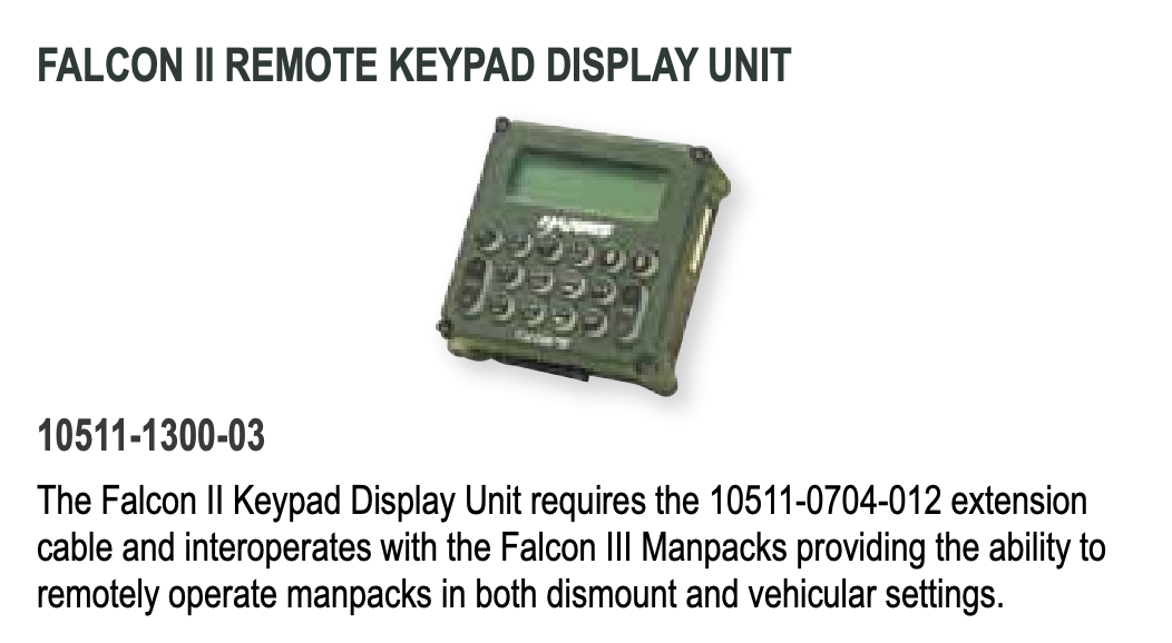
Harris Falcon II KDU Kit

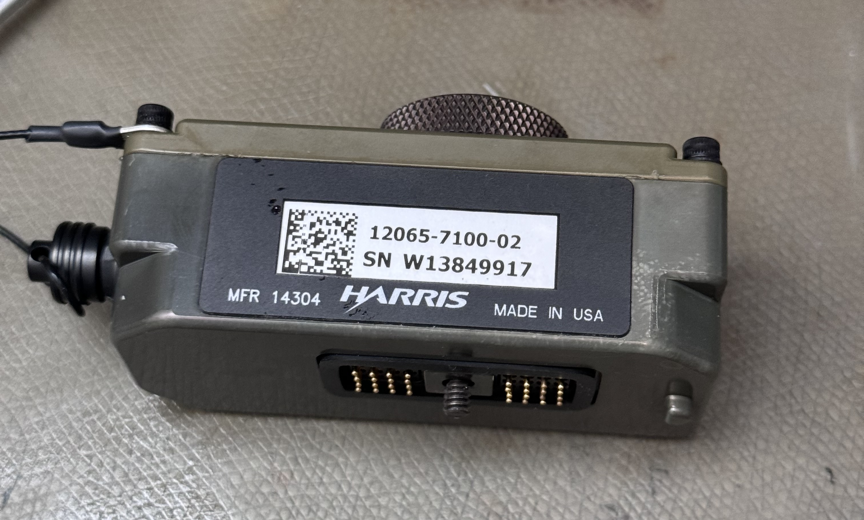
This article covers the Harris Falcon II KDU, P/N 10511-1300-03 and the associated cable and KDU-adapter P/N 12065-7100-02.
Table of Contents
Where was this used?
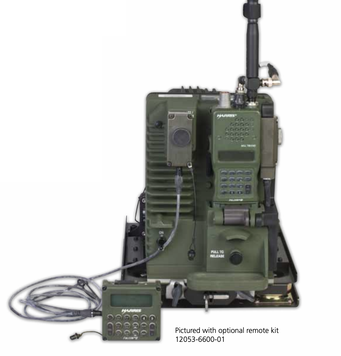
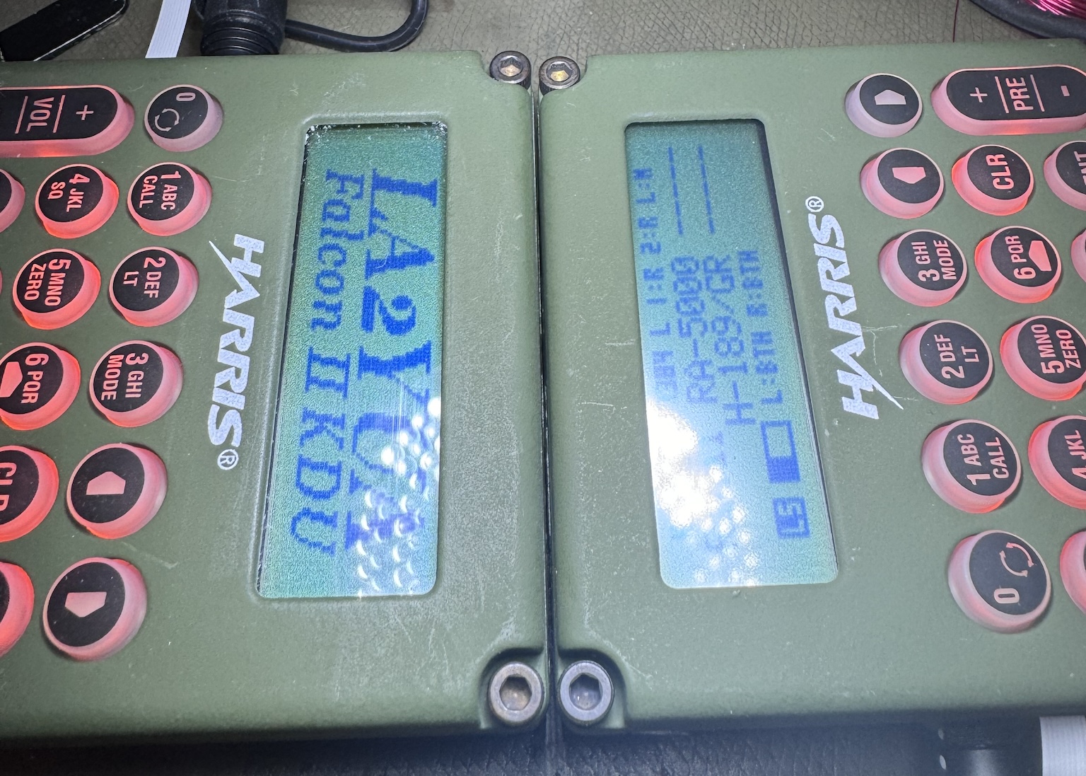
Above shows a view of the Harris AN/PRC-150 HF radio, with the associated KDU installed as the operator panel.
You may recognise the "CCI" marking shown above the Harris logo, short for "Controlled Cryptographic Item". This is an NSA classification, and ensures that the actual PRC-150 radio will be destroyed rather than resold to civilians. Fortunately, the KDU itself is not CCI and so can be freely exported.
The kit I sourced includes a long cable and a KDU adapter – and the KDU seems to be identical to the PRC-150 one. The adapter looks like it might be intended to fit a PRC-152 or similar handheld radio.
The adapter is identified by PRC68.com in their Harris RF-5800V article. Here they've also identified the 9+9 pad connector as the one used on the RF-5800V-HH. The RF-5800V-HH is a Falcon II predecessor to the Falcon III PRC-152 that e.g. only covers up to 108 MHz.
Frankly I think this adapter looks pretty ridiculous on the side of a PRC-152 but ok. It contains a bit of electronics which may be to e.g. boost the voltage from the PRC-152 (~11 V) to the 26.5 V the Falcon II KDU wants. I think it also converts TTL levels from the PRC-152 to the RS-422 levels the KDU uses.
As such it's most likely the kit I received was sold for use with PRC-152 radios, it seems to be most sensible when used with the VRC-110 vehicle mounting kit, where Harris marketing shows a configuration including this kit. Note also the weird plugs near the antenna, I think this is an inline adapter that keeps the antenna plugged into the radio, but routes the RF through the amplifier pack.
This KDU is also specified for use with the PRC-117 (RF-7800M-MP) which is also part of the Falcon III series:
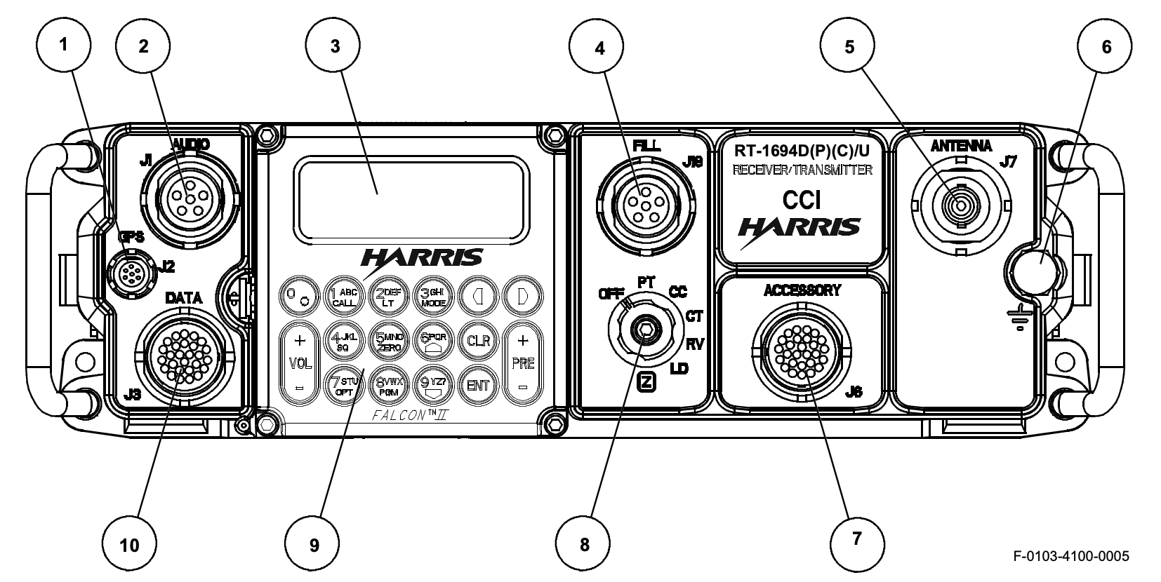
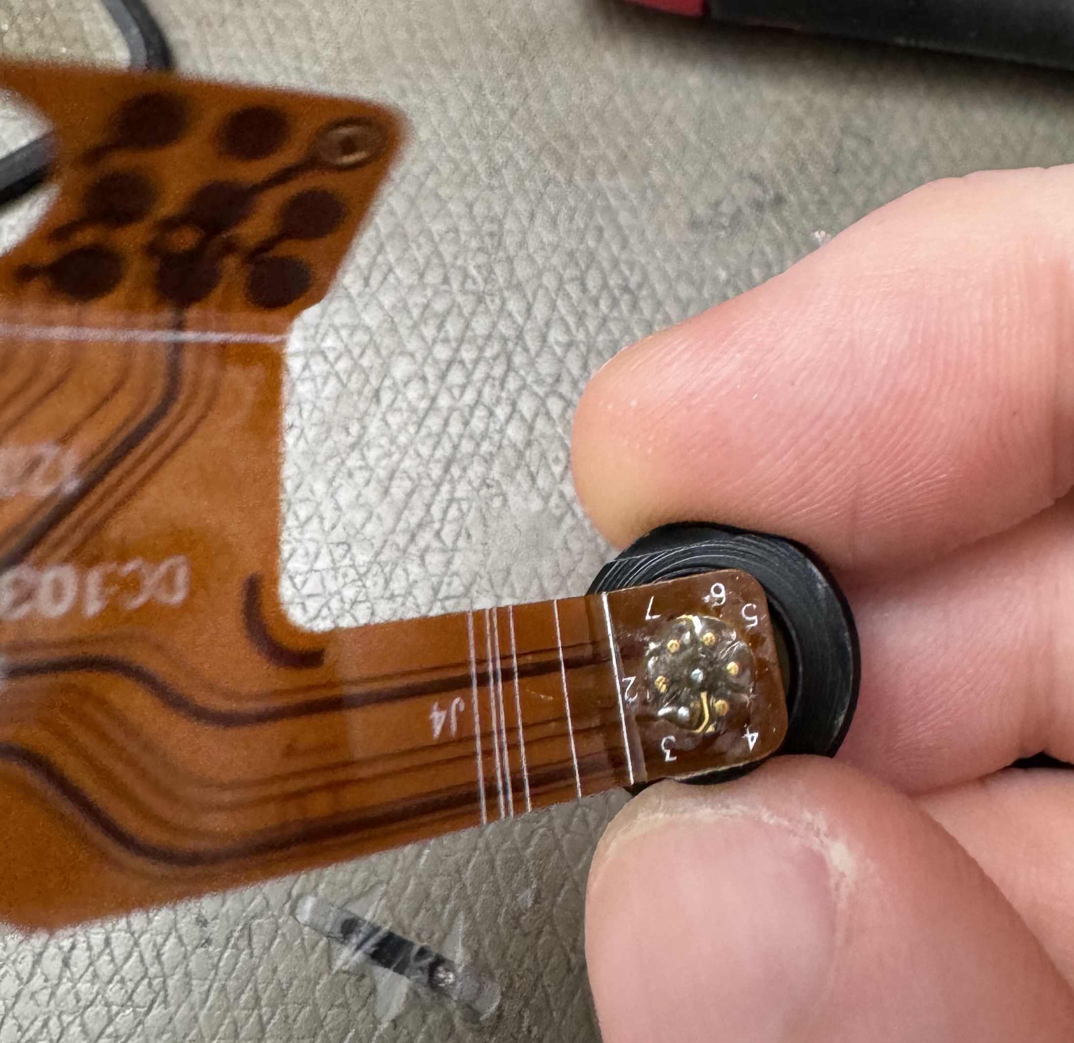
Pinouts
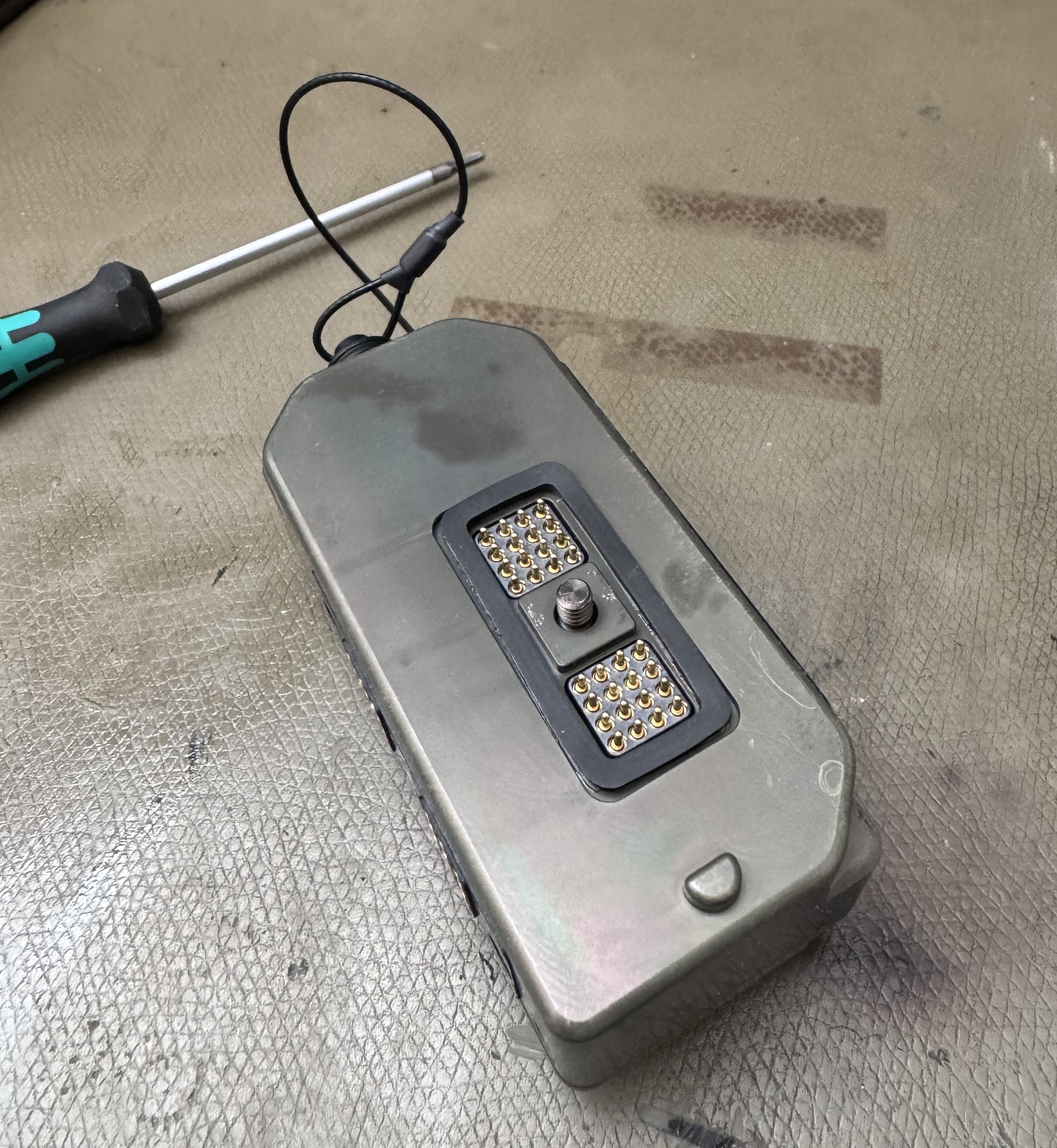
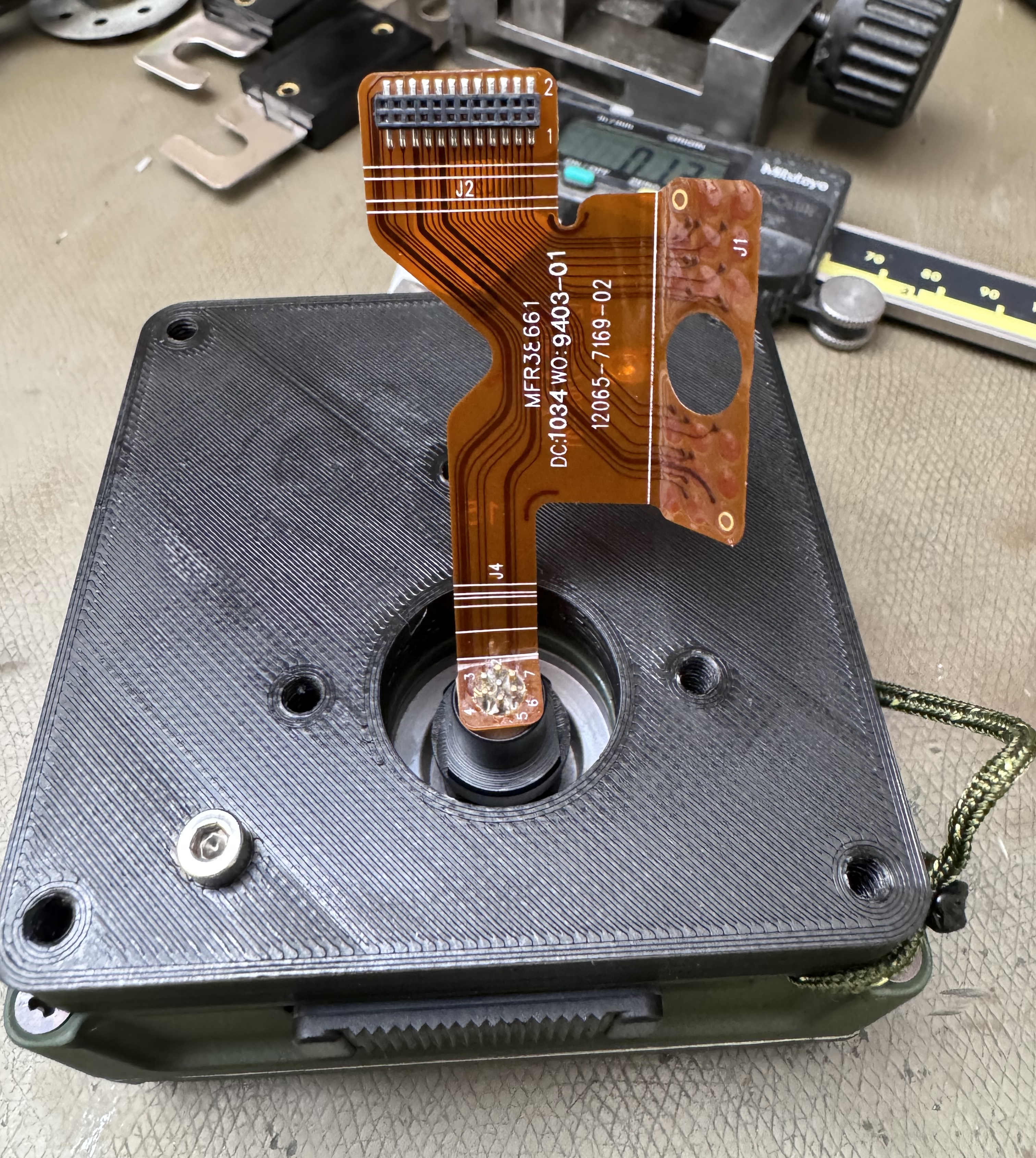
KDU
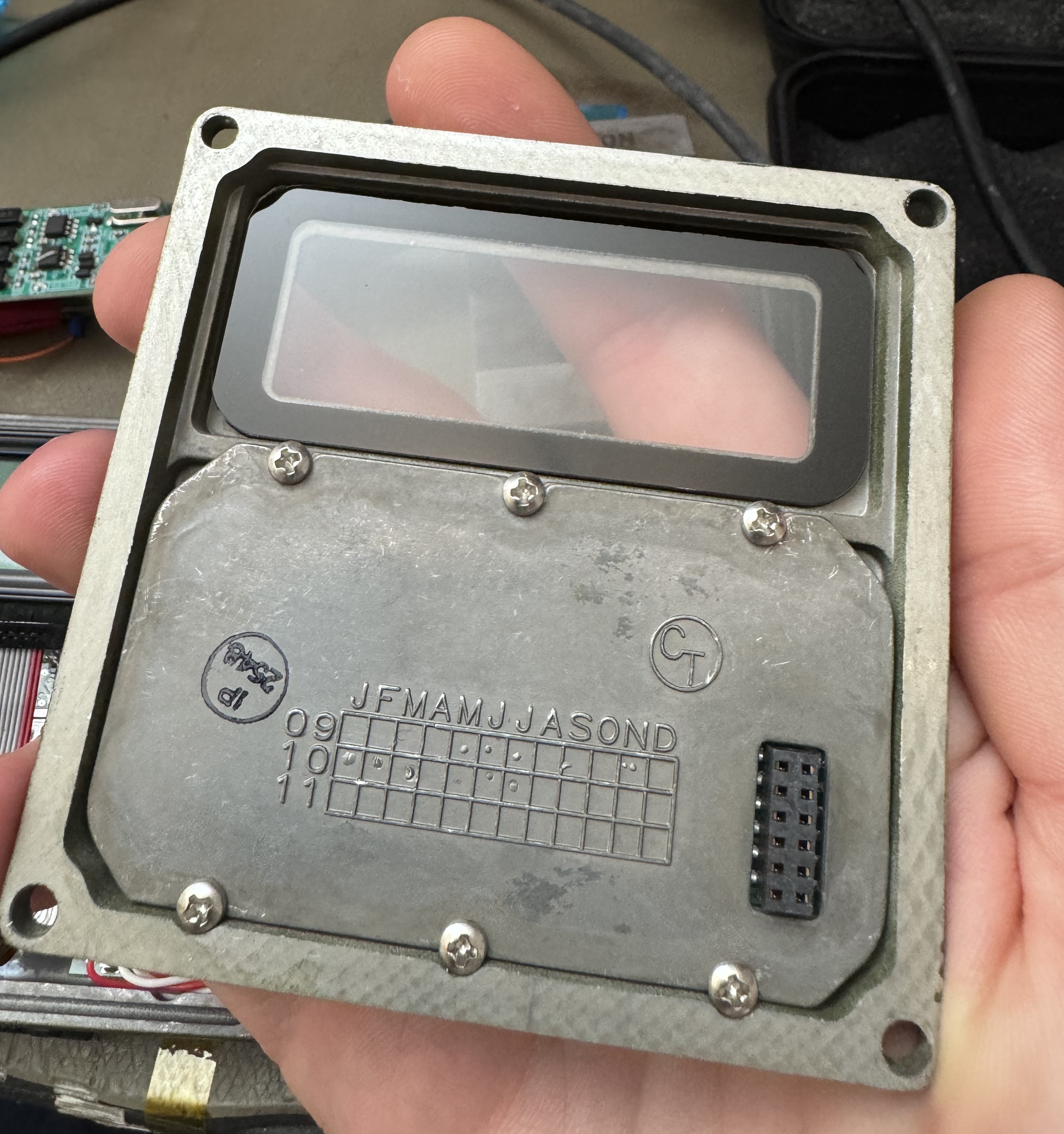
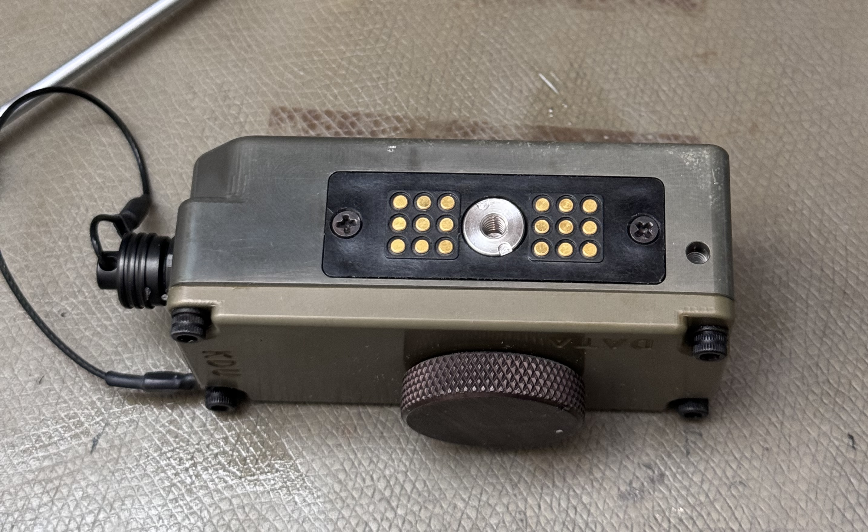
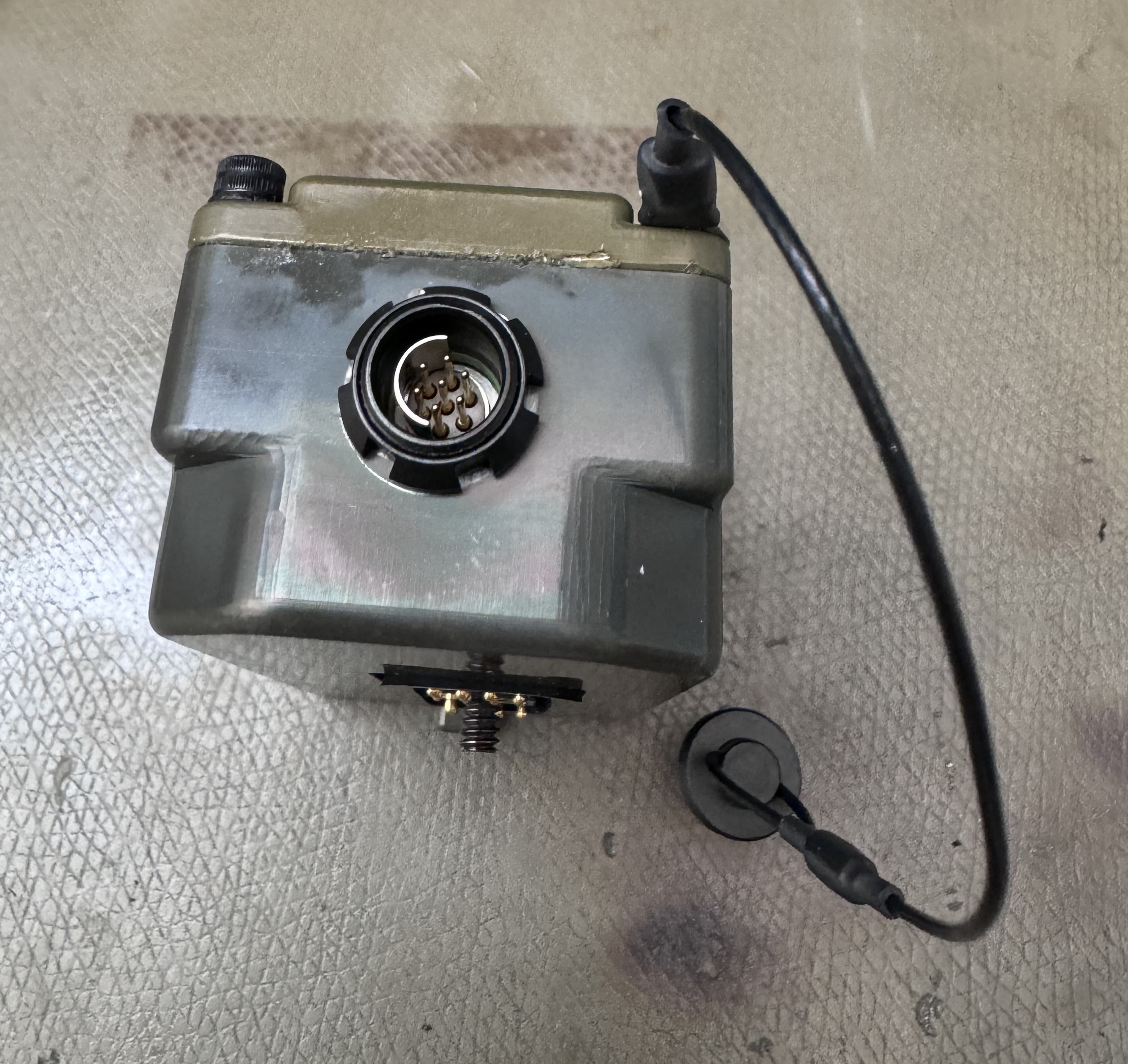
The KDU uses a 7 pin ODU MINI-SNAP® F panel connector on the left side. I believe a K20F1C-P07LCC0-400S 7 socket, shell size 0, orientation 1 plug is what fits on the KDU, but I haven't bought one to test.
The listed P/N to plug onto the radio end is a S10F1C-P07MCC0-4000, presumably the radio has a socket connector since that P/N is a pin connector that will not fit the KDU.
I found it more cost effective to just buy a second KDU+cable kit just to get a cable to reuse.
The rear pin seems to be a slightly custom modification, it's the same connector but with sockets and inside a plug shell without any connector retention features. I believe the panel mount G10F1C-P07MCC0-0000 or the cable mount K10F1C-P07MCC0-5000 will fit. Both of these seem to be unobtainium at the time of writing, but you could harvest the panel mount connector from the PRC-152 adapter since that will fit.
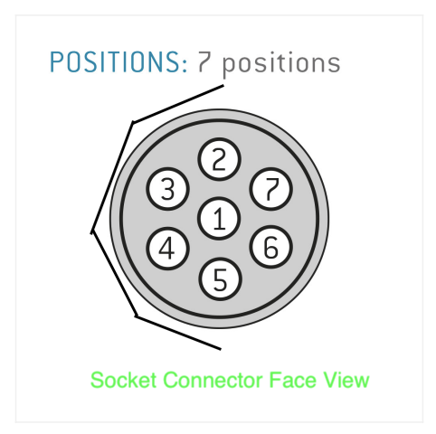
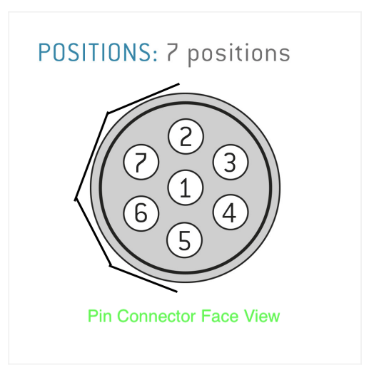
Above shows the pinout for looking into the face of socket and pin connectors.
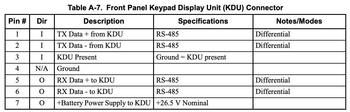
Above an excerpt from Appendix A of the PRC-150 Operation Manual (10515-0103-4100) shows the KDU pinout. Not sure why RS-485 is listed given it seems to be a RS-422 interface.
Cable
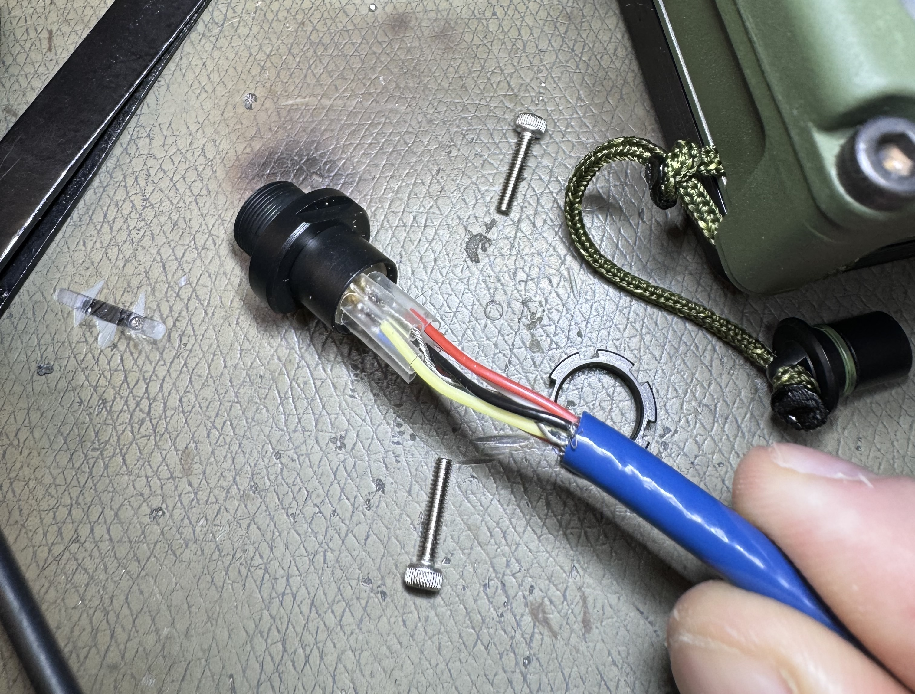
The cable P/N 10511-0704-040 (40 feet?) rev T is a thin and weird but nice feeling socket-socket cable.
It has shielding and an internal drain wire, and 6 coloured wires.
| Wire Colour | Socket No. | Function (ref Table A-7) |
| █ Black | 1 | KDU TX+ |
| █ White | 2 | KDU TX- |
| █ Red | 3 | Grounded in KDU |
| █ Shield/Drain Wire | Case & 4 | Ground, power return |
| █ Brown | 5 | KDU RX+ |
| █ Blue | 6 | KDU RX- |
| █ Orange | 7 | +26.5 V supply |
To verify you've got things mostly right, check Red to Ground, I read around 47 Ω. RX+/RX- should have around 220 Ω across it.
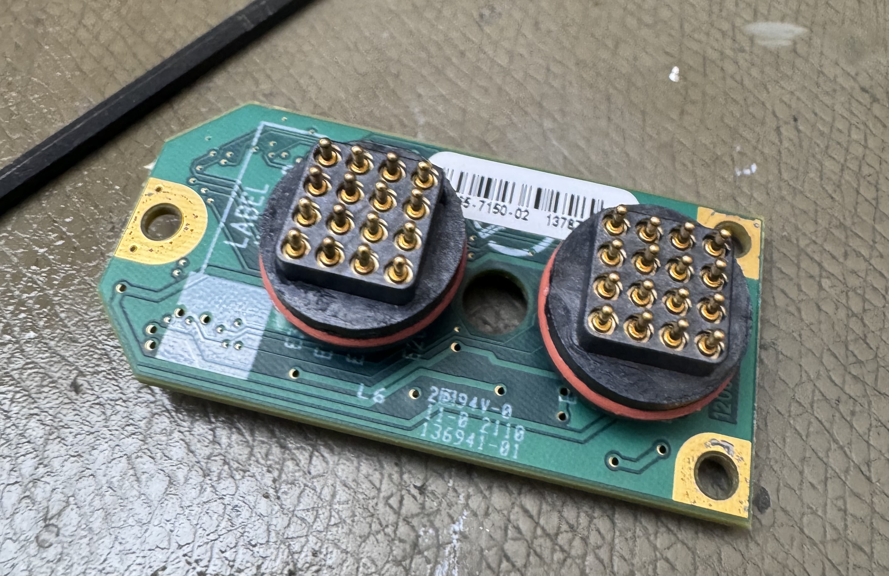
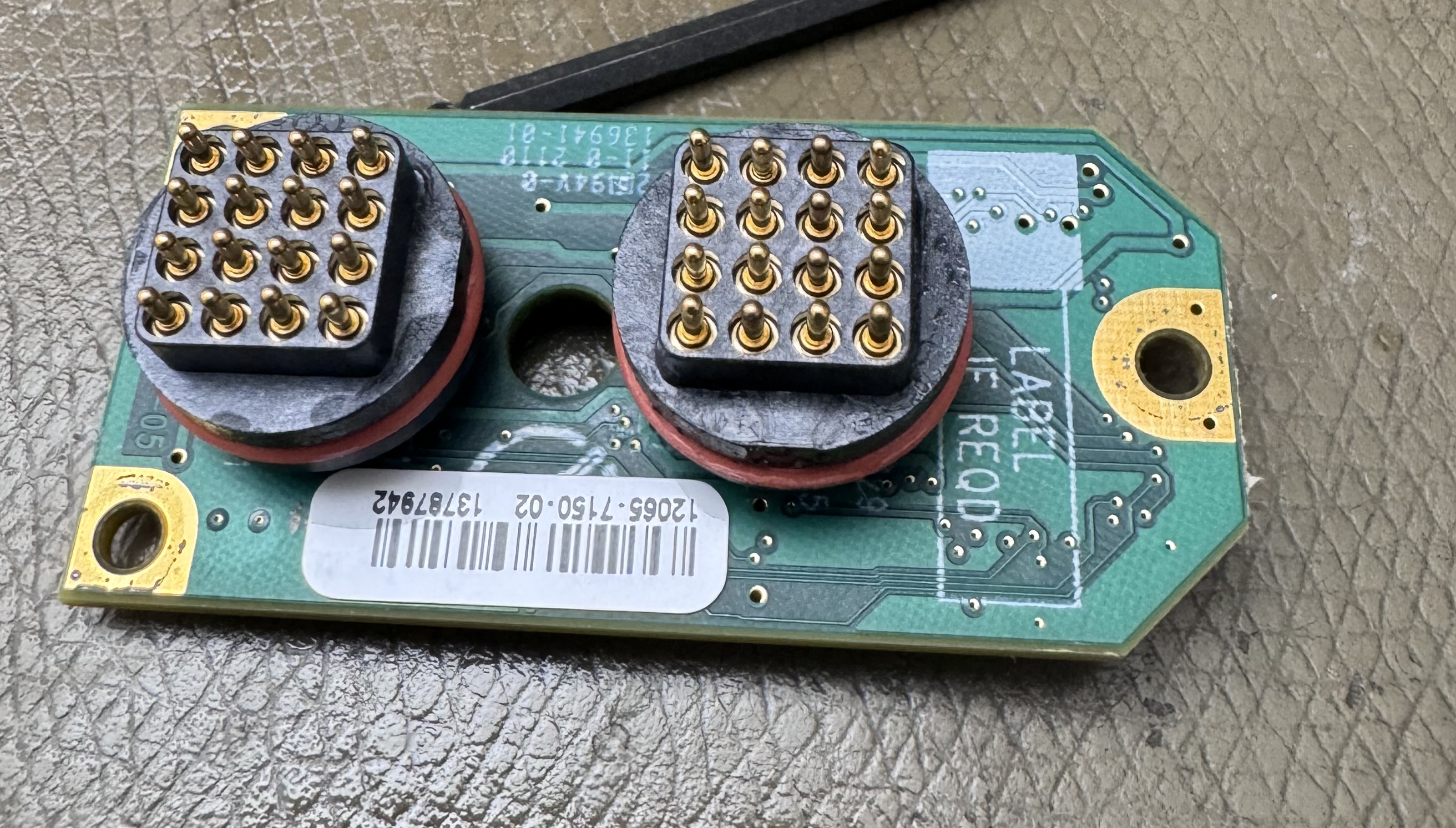
PRC-152 adapter pinout
The PRC-152 aux connector is not publicly documented as far as I know, but we can infer some of the pins from analysis of the adapter used here.
As mentioned above, the 9+9 pad connector is identified by PRC68: Harris RF-5800V so we know what goes there.
The pad numbering is labelled on the adapter PCB, and looking at the radio it looks like this:
| 19 | 30 | 31 | 32 |
| 25 | 26 | 27 | 28/GND |
| 21 | 22 | 23 | 24 |
| 17 | 18 | 19 | 20 |
| - | - | - | - |
| 13/DC out? | 14 | 15 | 16 |
| 9 | 10 | 11 | 12 |
| 5 | 6 | 7 | 8/GND |
| 1 | 2 | 3 | 4 |
I didn't bother trying to probe out every connection, but this board and the adapter to the old-style expansion port with a known pinout does provide a partial Rosetta stone that could be used to work out most of the pin functions.
This numbering scheme is consistent with the 2x9 pad connector listed in PRC68.
Interfacing
The KDU will power up at around 12 V minimum. On startup it doesn't seem to do much other than show a Harris logo. The serial port seems to operate at 19200-8N1.
When keys are pressed, a sequence of bytes is output where two bytes seem to indicate which key was pressed.
This is actually somewhat similar to the TRI PRC-152 KDU interface, though that KDU uses ASCII outputs for the keys, and it continuously transmits the state instead of being reactive.
Serial Data Output
The KDU outputs a short packet whenever a key is pressed – pressing multiple keys seems to d0 nothing.
The output seems to always start with:
0x88 08 24 01 25 xx xx xxThe last three bytes seem to change in sequence with some internal key number, for example the '0' key outputs 0D 46 E7, and the 1 key sends a 0E 47 E8. This seems redundant, so presumably some checksum is part of this payload.
The sequence for '0' without the last two bytes:
0x88 08 24 01 25 0DHas a sum of bytes (modulo 256) of E7, the last byte is therefore likely the sum of the packet bytes, excluding the last two bytes.
The purpose of the second to last byte is not known, it seems to always be 0xA1 less than the last byte, or 0x39 larger than the key byte.
The table below lists the 6th byte of the emitted string and the corresponding physical key:
| 0 | 0x0D | 1 | 0x0E | 2 | 0x0F | 3 | 0x10 | < | 0x11 | > | 0x12 |
| V+ | 0x07 | 4 | 0x08 | 5 | 0x09 | 6 | 0x0A | CLR | 0x0B | P+ | 0x0C |
| V- | 0x01 | 7 | 0x02 | 8 | 0x03 | 9 | 0x04 | ENT | 0x05 | P- | 0x06 |
Control interface
I decided to just linear fuzz the interface to see what happened, this could potentially take years to cover all combinations so it's not a great way to accomplish anything really.
Sending: b'8e62000000000000'
Received: b'88 08 24 01 26 00 3b db' (NACK)
Corrupted data in upper left section of the logo some time after this. The sequence did not return anything on the next attempt.
Continuing through xx77000000000000 entire screen starts going weird. Repeating from 0x85 60 did not make the same thing happen – it seems to crash after some time fuzzing. Likely the length byte being set too long causes an overflow.
Sending: b'8808240125000156'
Received: b'88 08 24 01 26 00 3b db – maybe a NACK? This response seems to happen a lot when fuzzing this region.
Hot-plugging:
Received: b'88 08 24 01 26 00 3b db fc' one time - looks like last byte is in errorReceived: b'88 09 24 01 24 00 00 17 da' every hot-plug event.
NACK from: b'e3083e9acb930021' to b' e3 08 3e 9a cb 93 00 21'
Received: b'3030. 88 08 24 01 26 01 3c dc 8808240126013cdc' then crashed. Delta A0
Byte 2 seems to be total packet length.
After this effort, I decided that this was pointless, and decided to instead attempt to dump the flash memory of the device. Failing this, I will simply make my own controller PCB. Stay tuned for future articles on this topic.
Internals
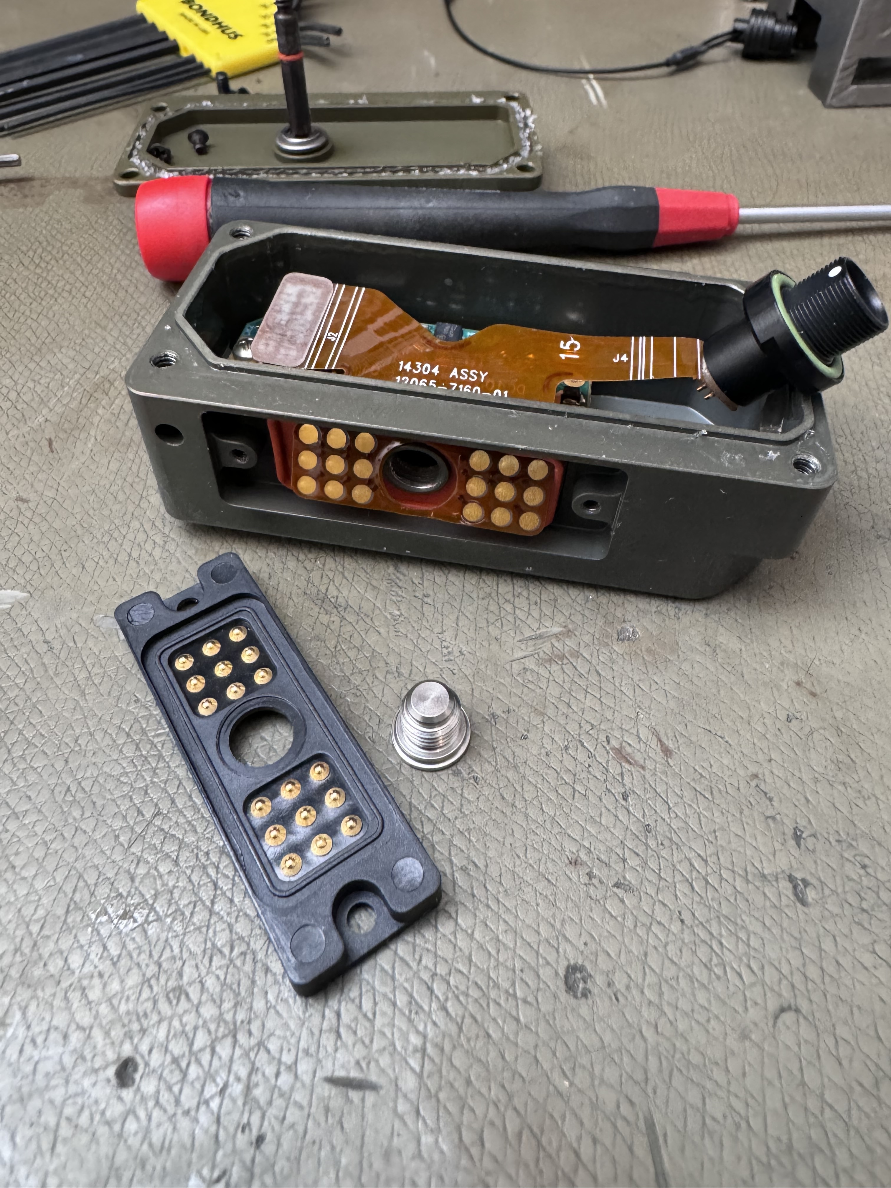
KDU
The KDU itself it pretty easy to take apart, and uses a flex-PCB for connector interfacing, a main PCB with interfaces, processor, and display. All you have to remove to get at the internals is the four corner screws, using a 7⁄64" allen key.
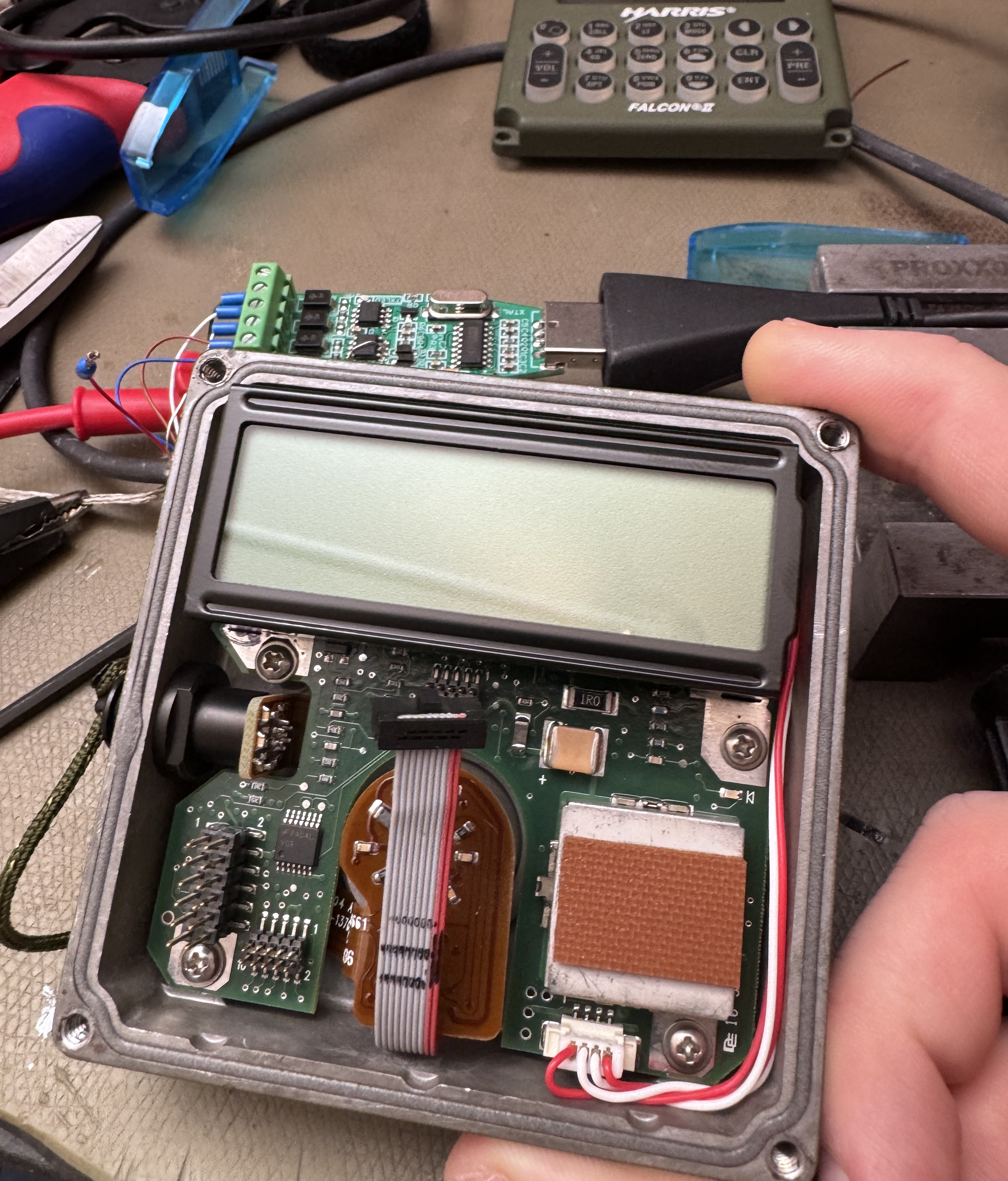
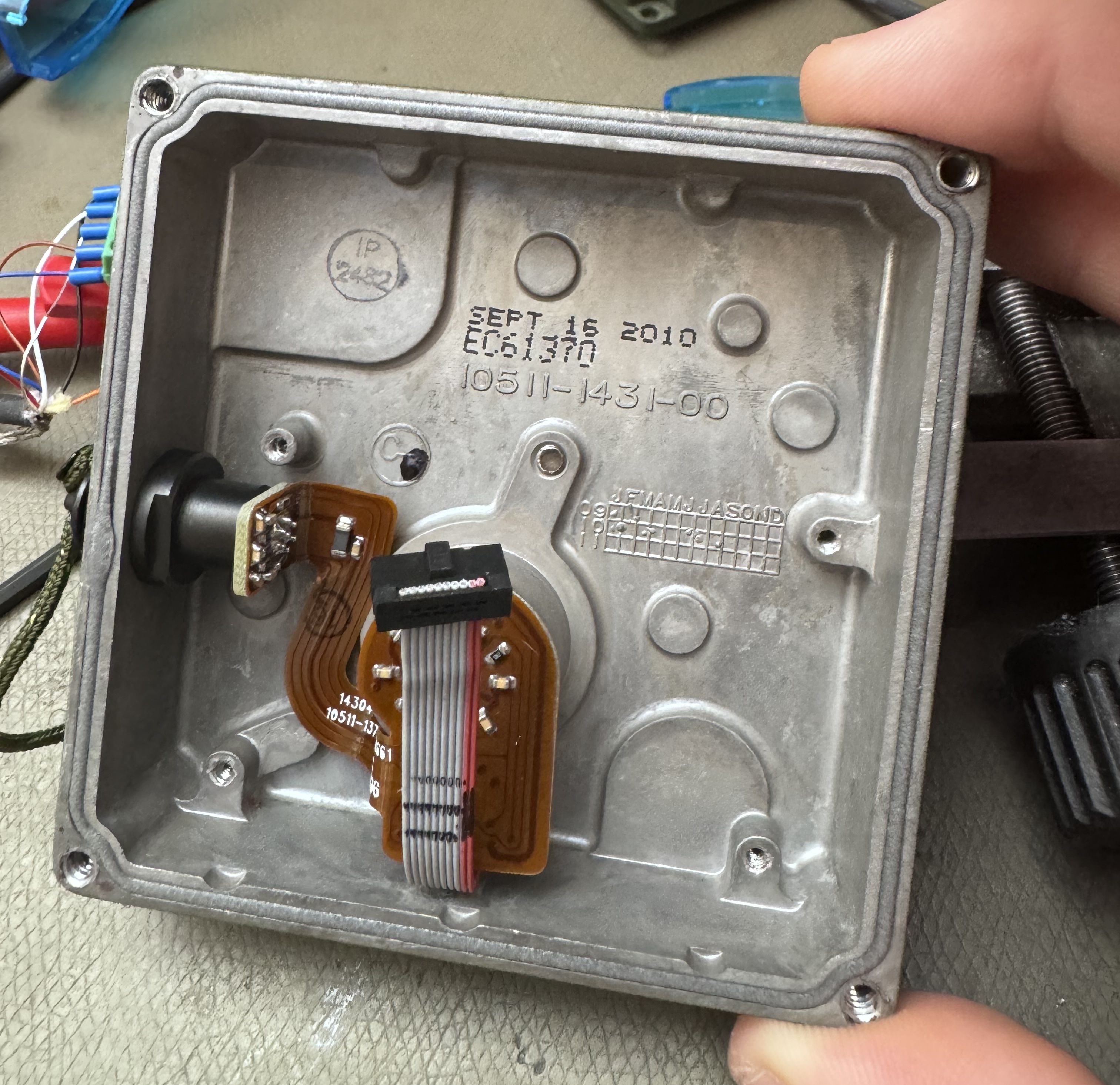
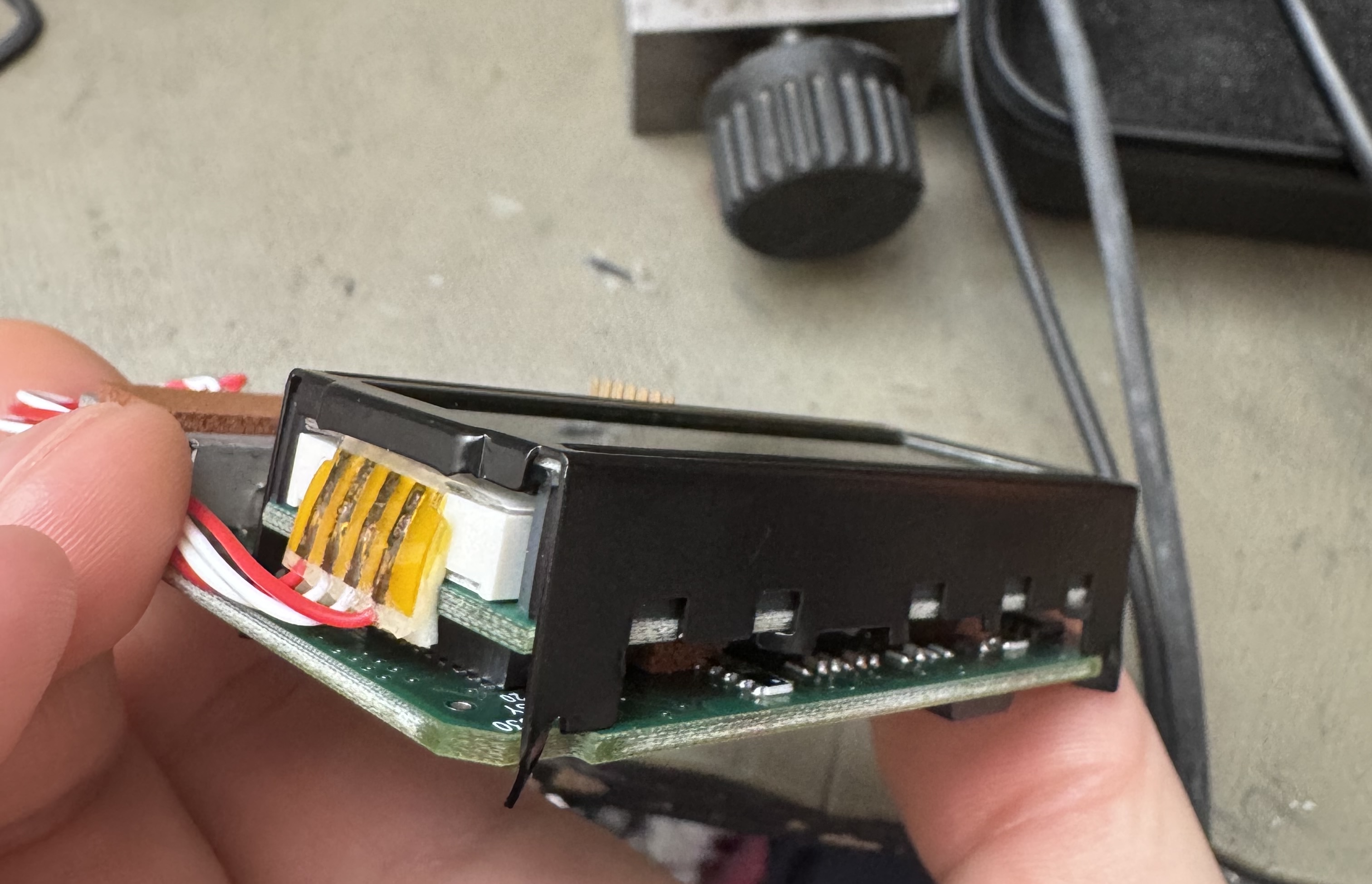
The keypad is a separate PCB inside a cast enclosure with a 0.1" header acting as a board to board connector, when taking the front panel off the keypad connector is to the lower left and should be levered loose first to avoid bending it.
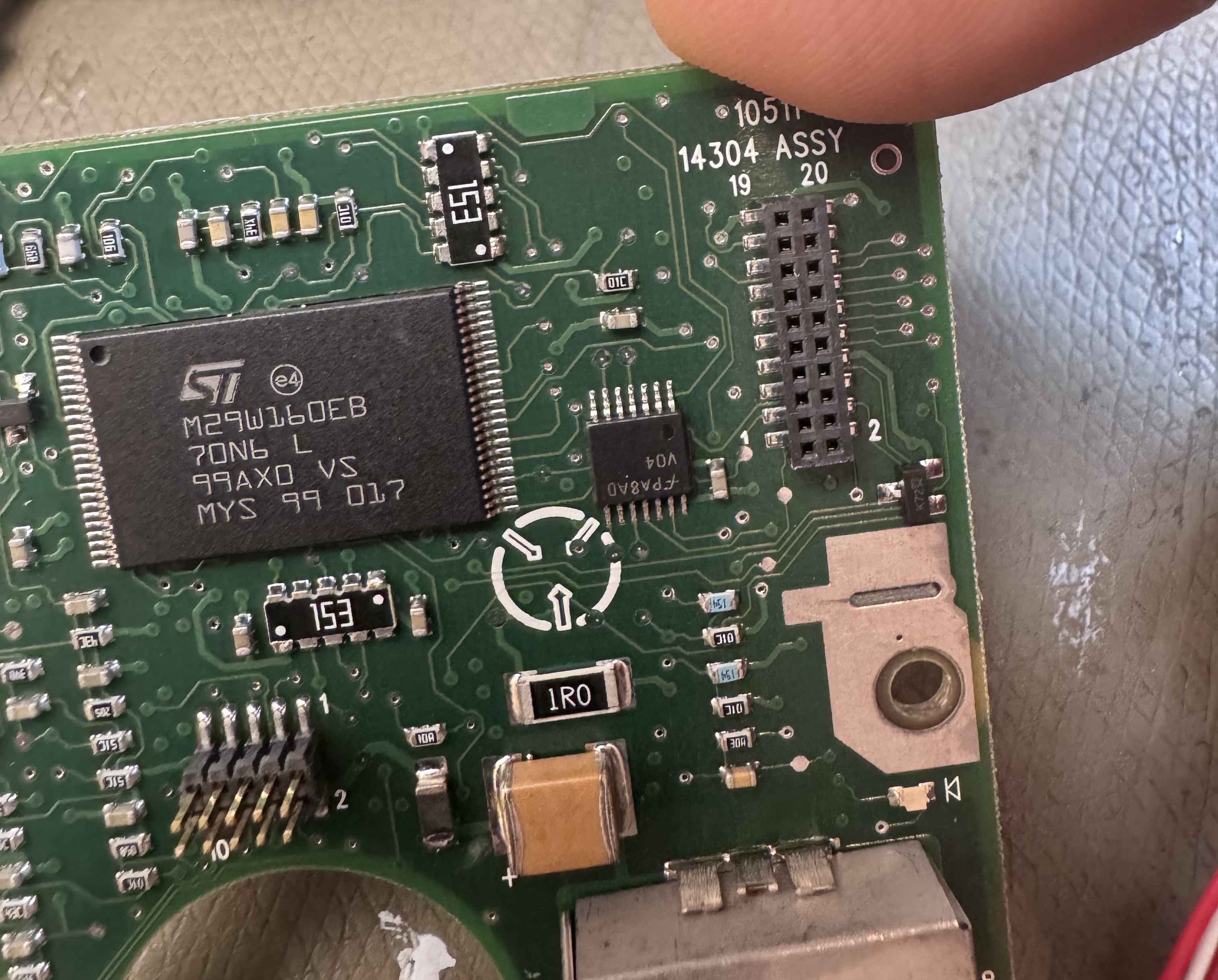
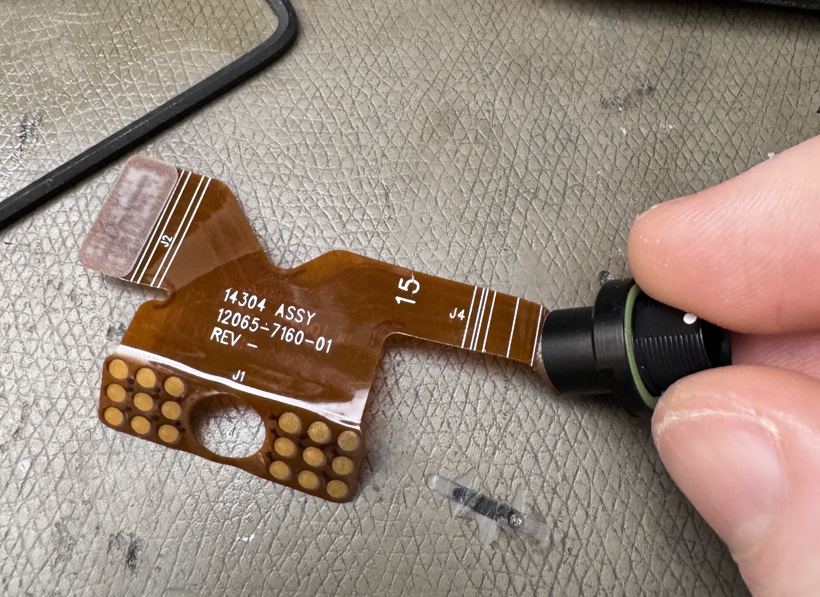
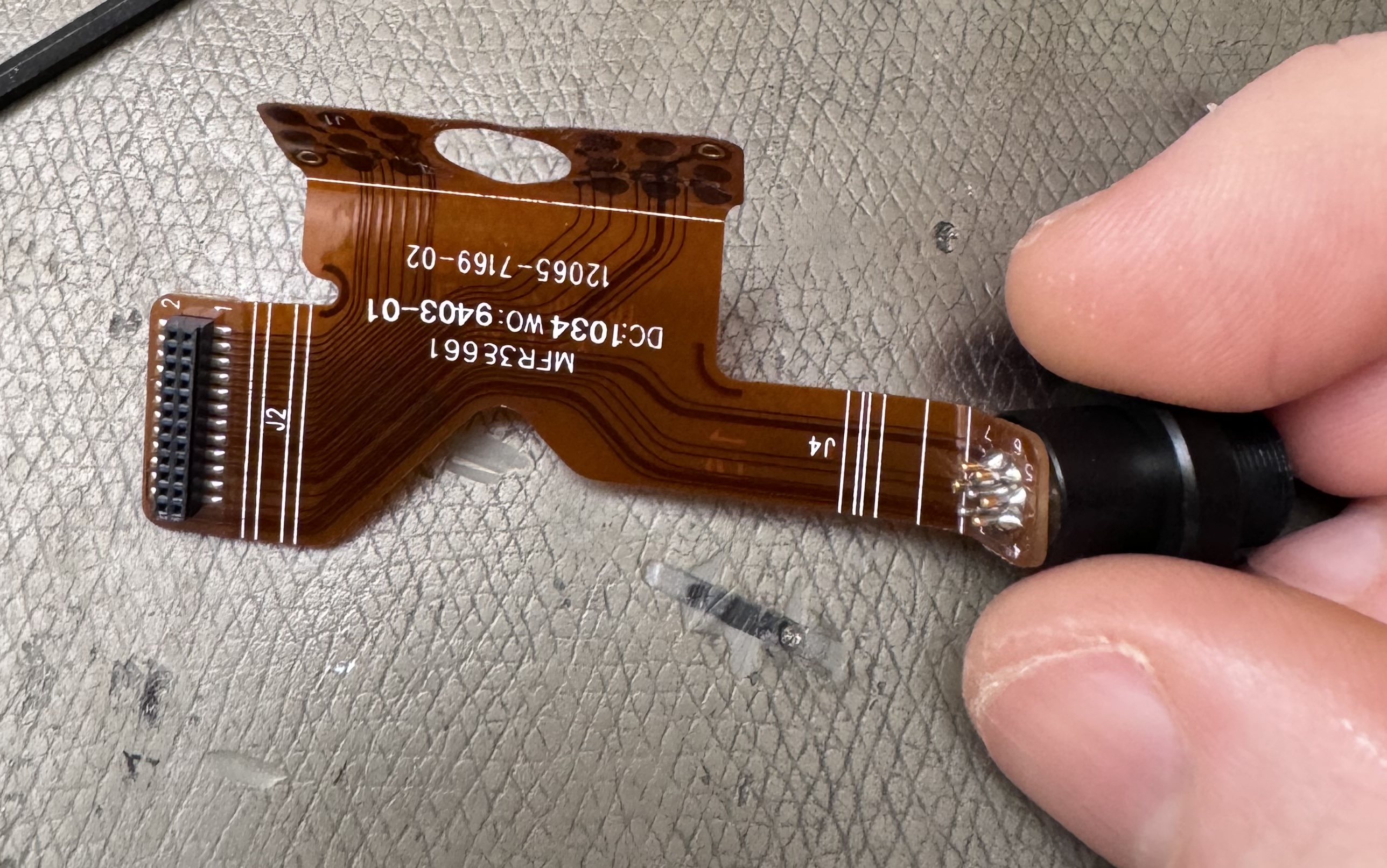
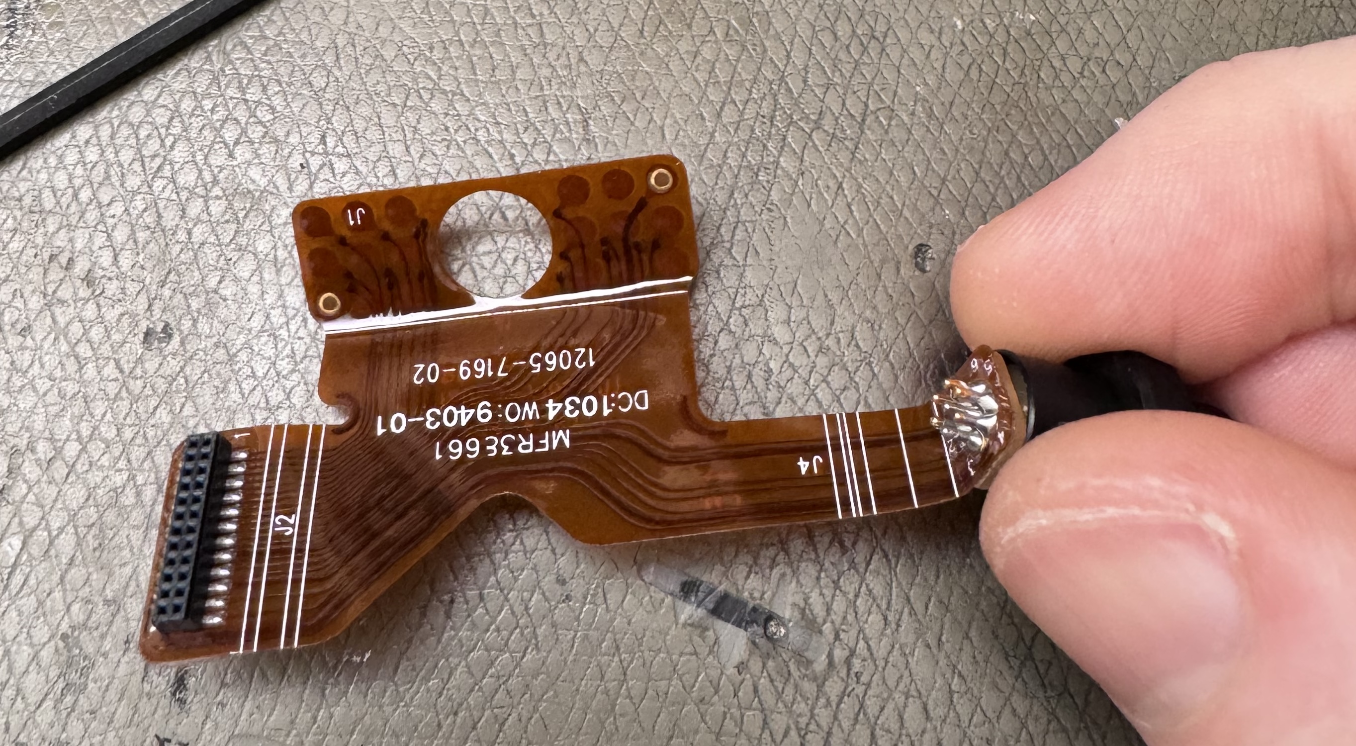
The external connectors are paralleled via a flex-rigid assembly and connects to a 2-row 0.05" pin header.
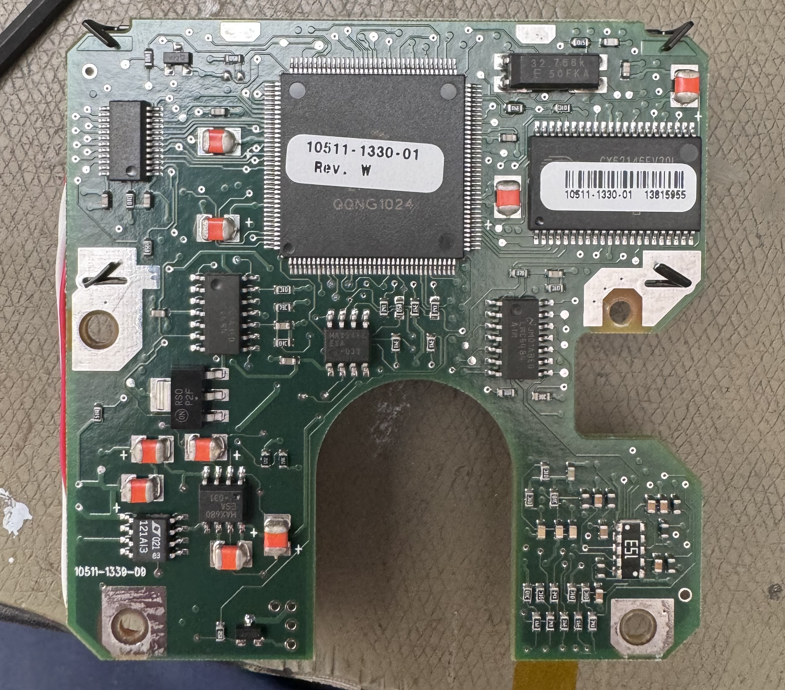
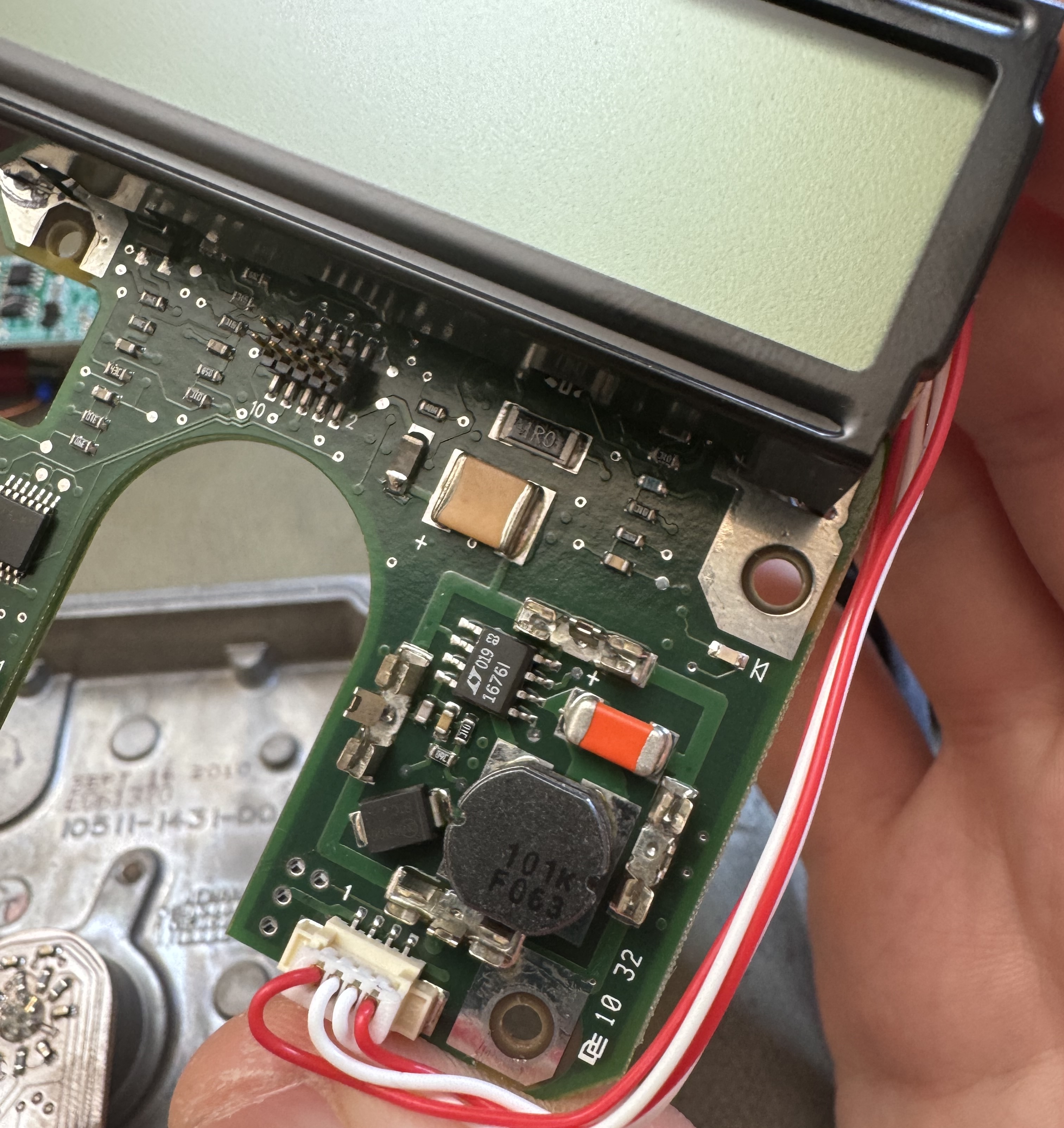
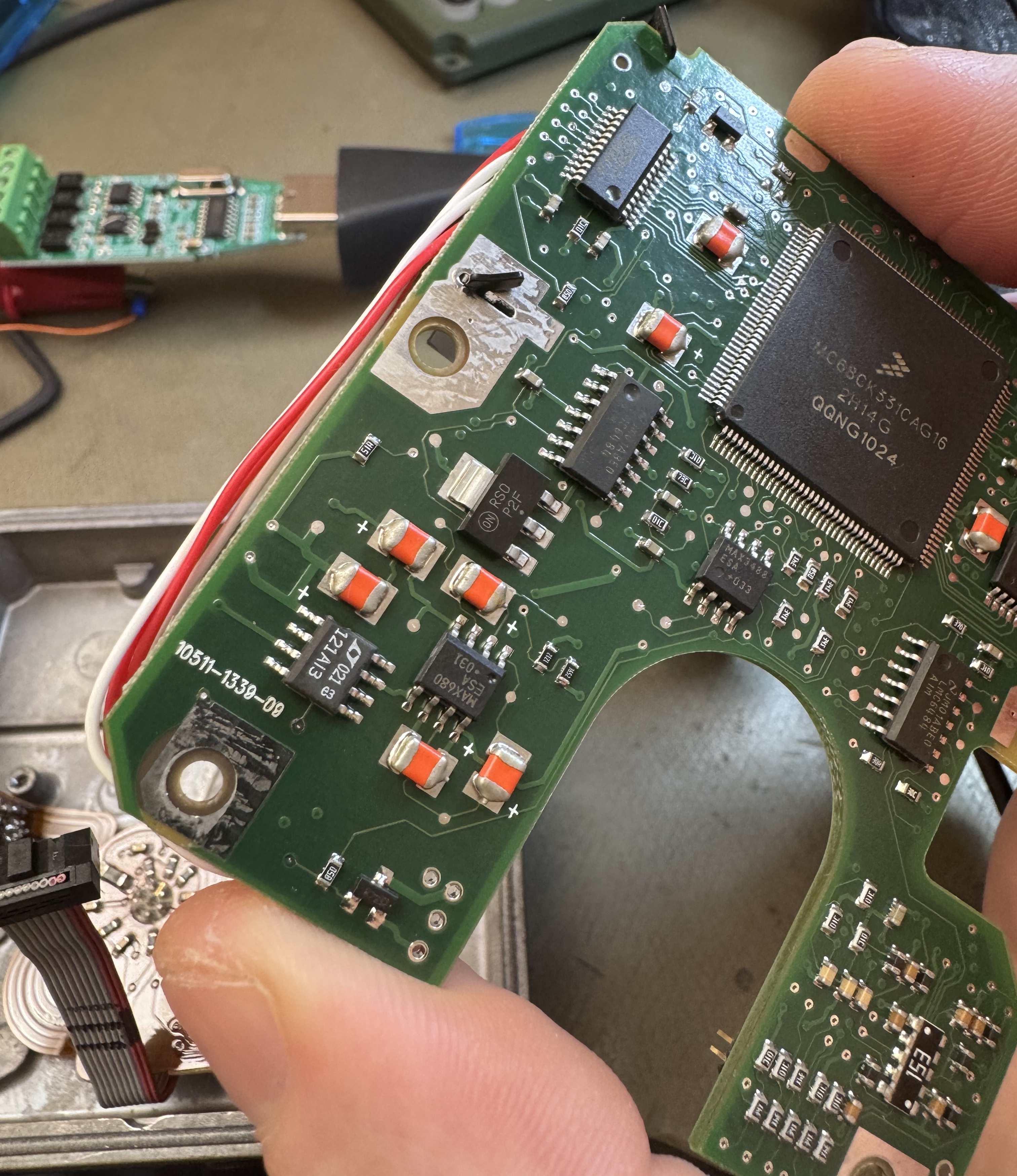
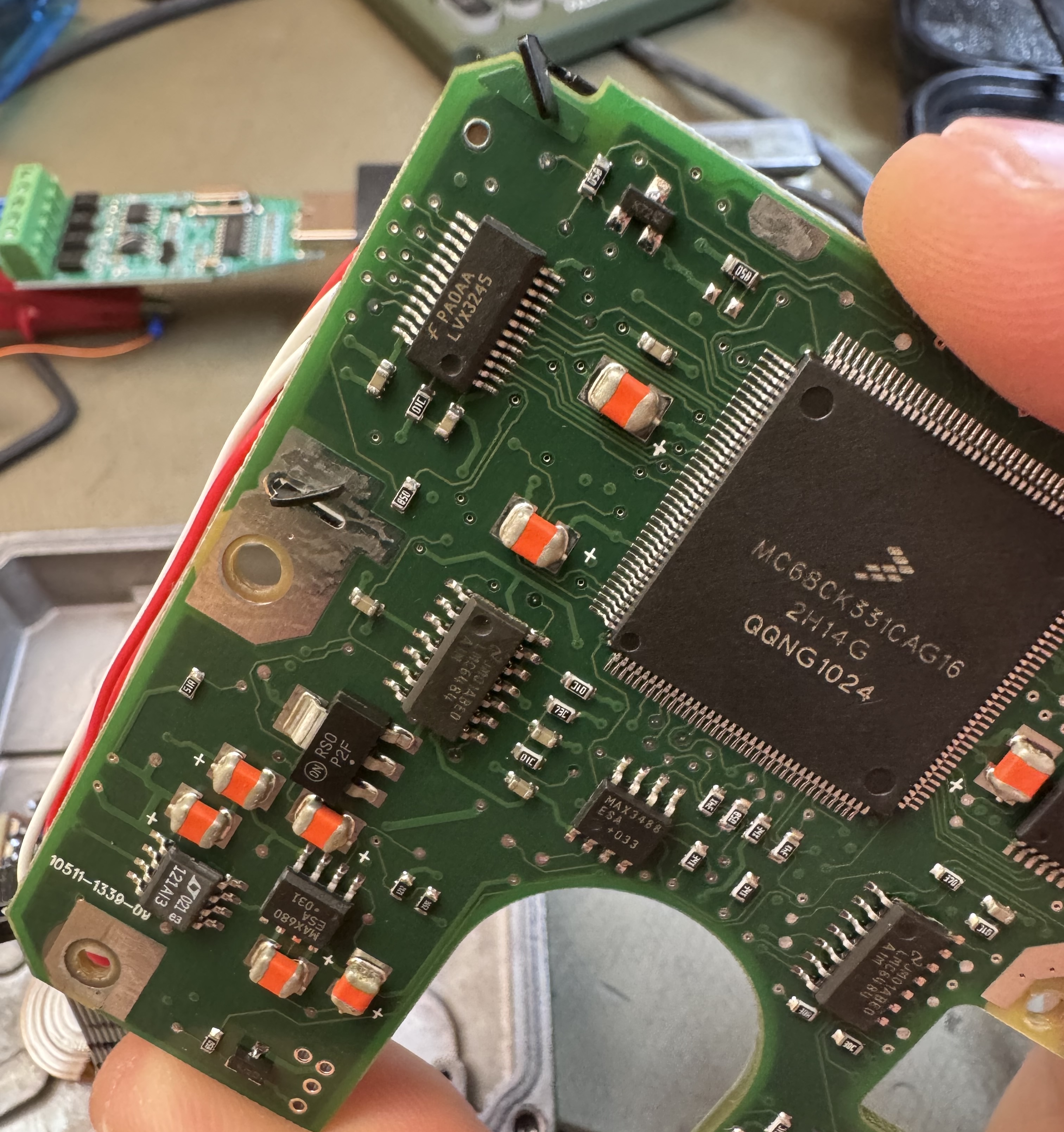
A shielded can contains a DC/DC converter controlled by a LT1676. A MAX680 charge pump is probably used for LCD biasing, and there's two LDO's.
A MAX3488 slew-rate limited RS-422 transceiver is no surprise, but this is a nice part since it has limited slew rate for improved EMI performance.
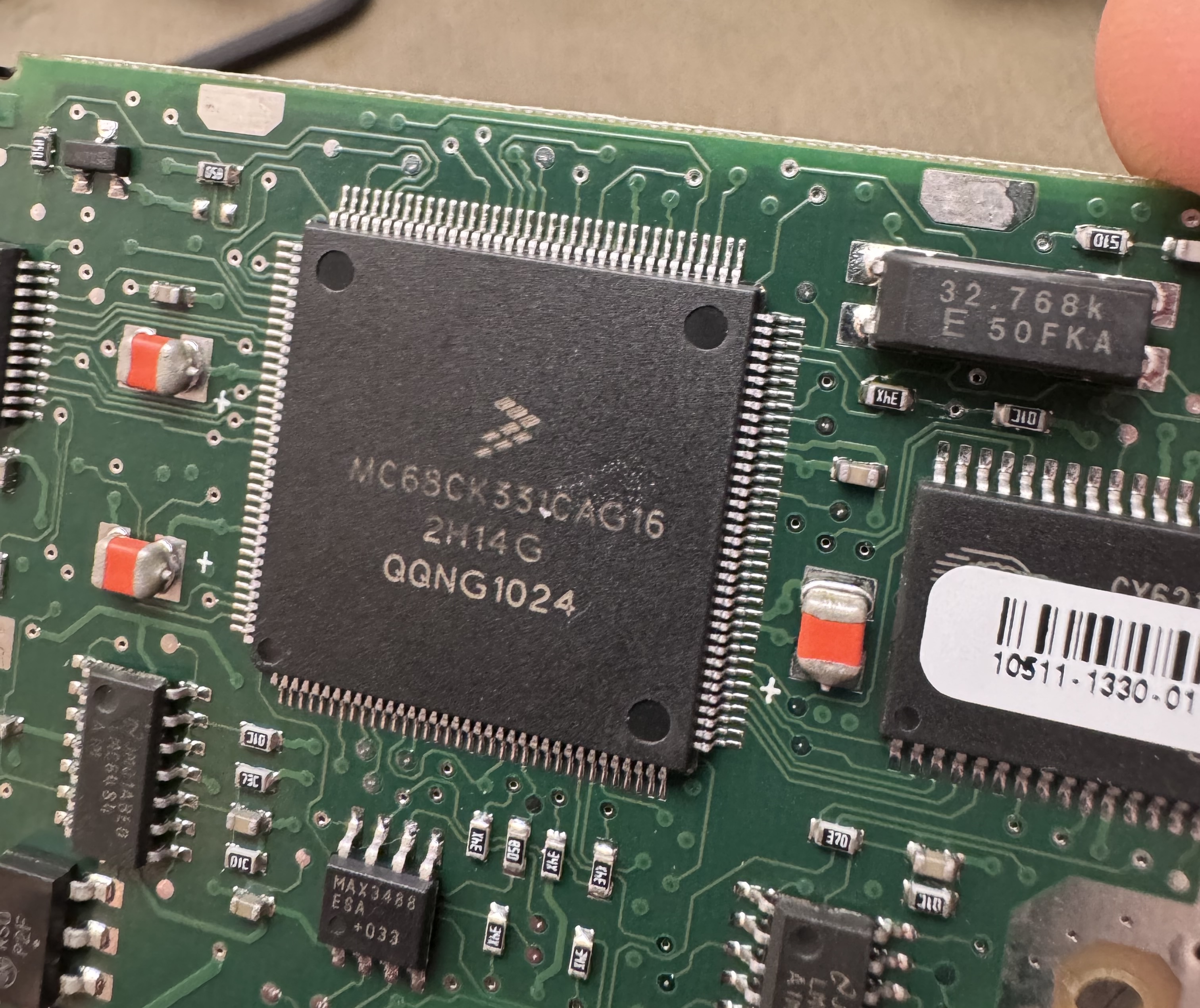
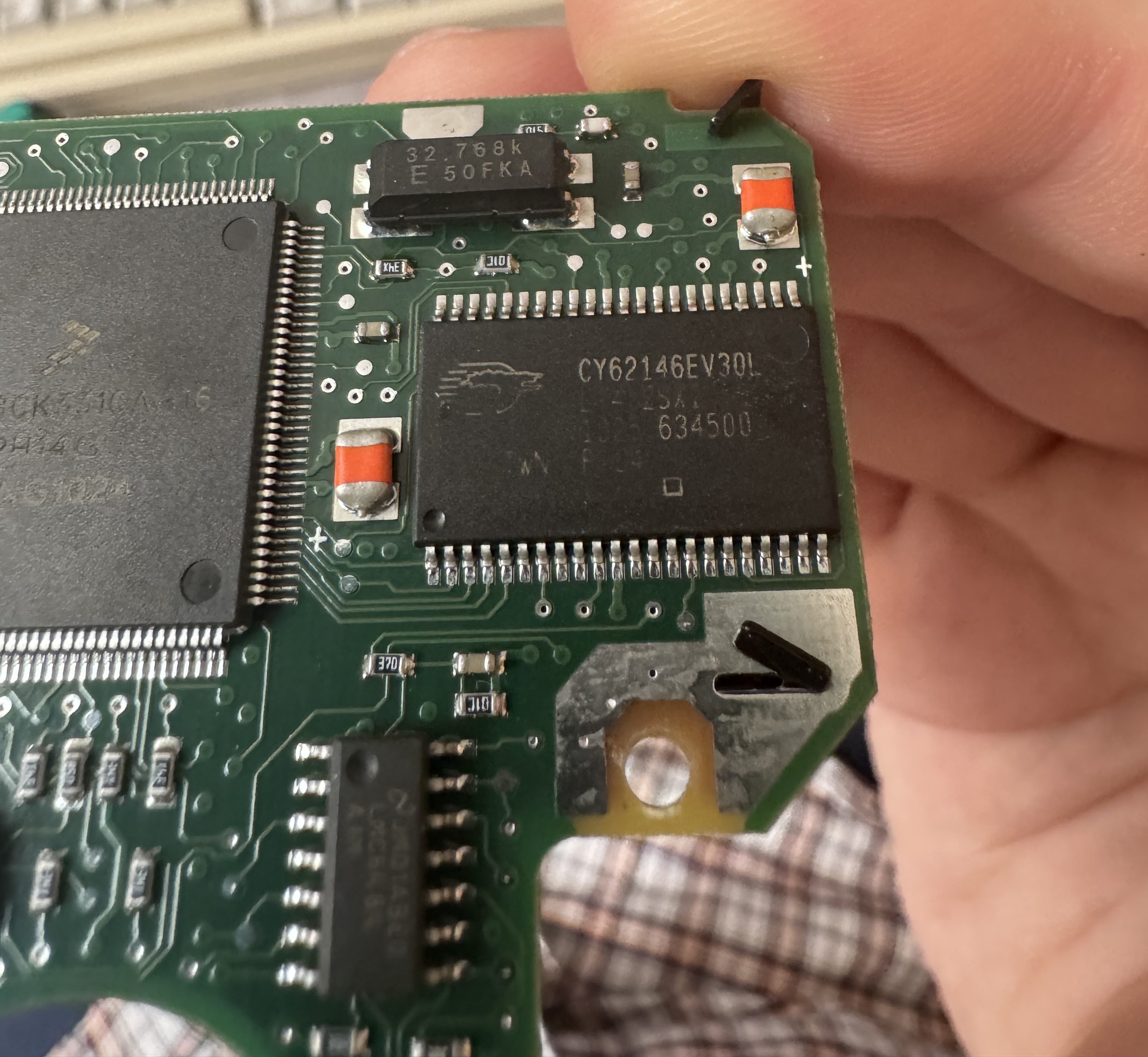
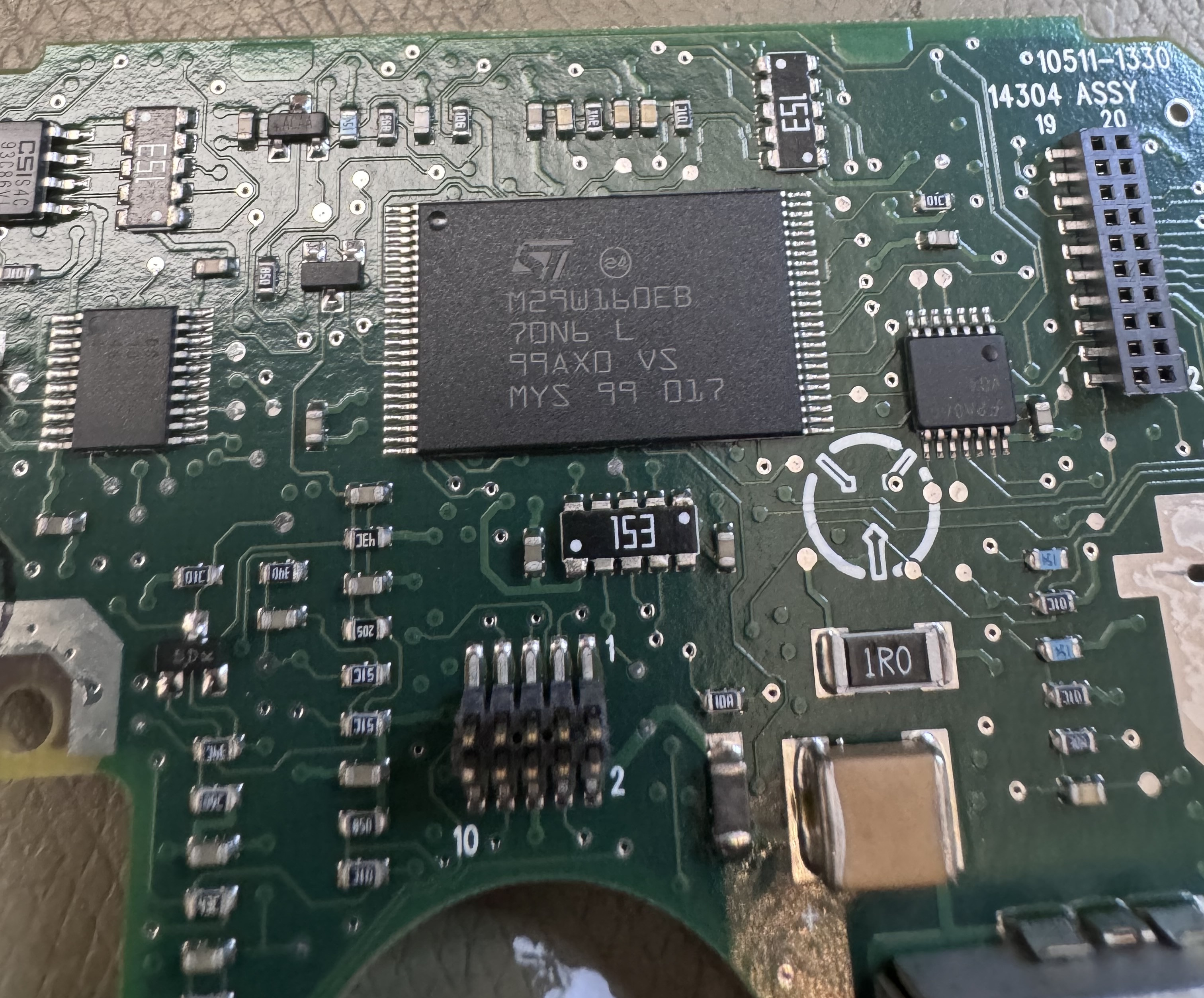
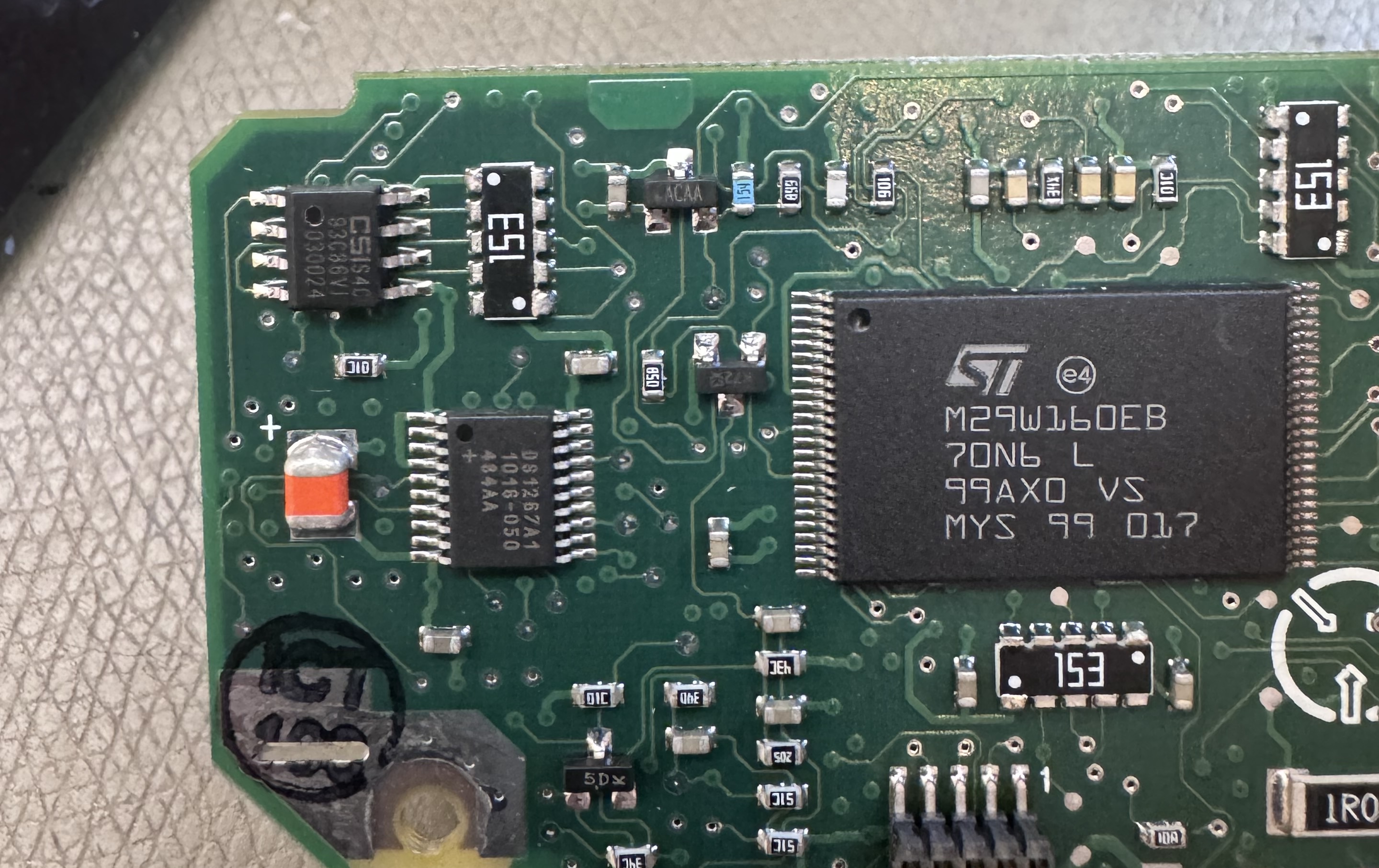
A Freescale MC68311 processor (MC68CK331CAG16) with external flash and SRAM is used to drive the display and read the keypad – given the era (~2001?) this is not a surprising choice. There is a small header on the corner of the PCB that may be a JTAG port.
The SRAM is a CY62146 4 Mbit type, and the M29W160EB 16 Mbit flash is under the LCD. Other highlights include a DS1276 "DigiPOT" type DAC, which probably controls the LCD contrast and maybe the backlight, and a 93C86 2 kb SPI EEPROM for parameter storage.
LCD
The LCD is connected via a low profile 20 pin header (0.05" pitch). There is a 4 pin connector coming off the LCD. I spent a lot of time trying to work out what this was for, before finally dismantling the LCD module a bit more.
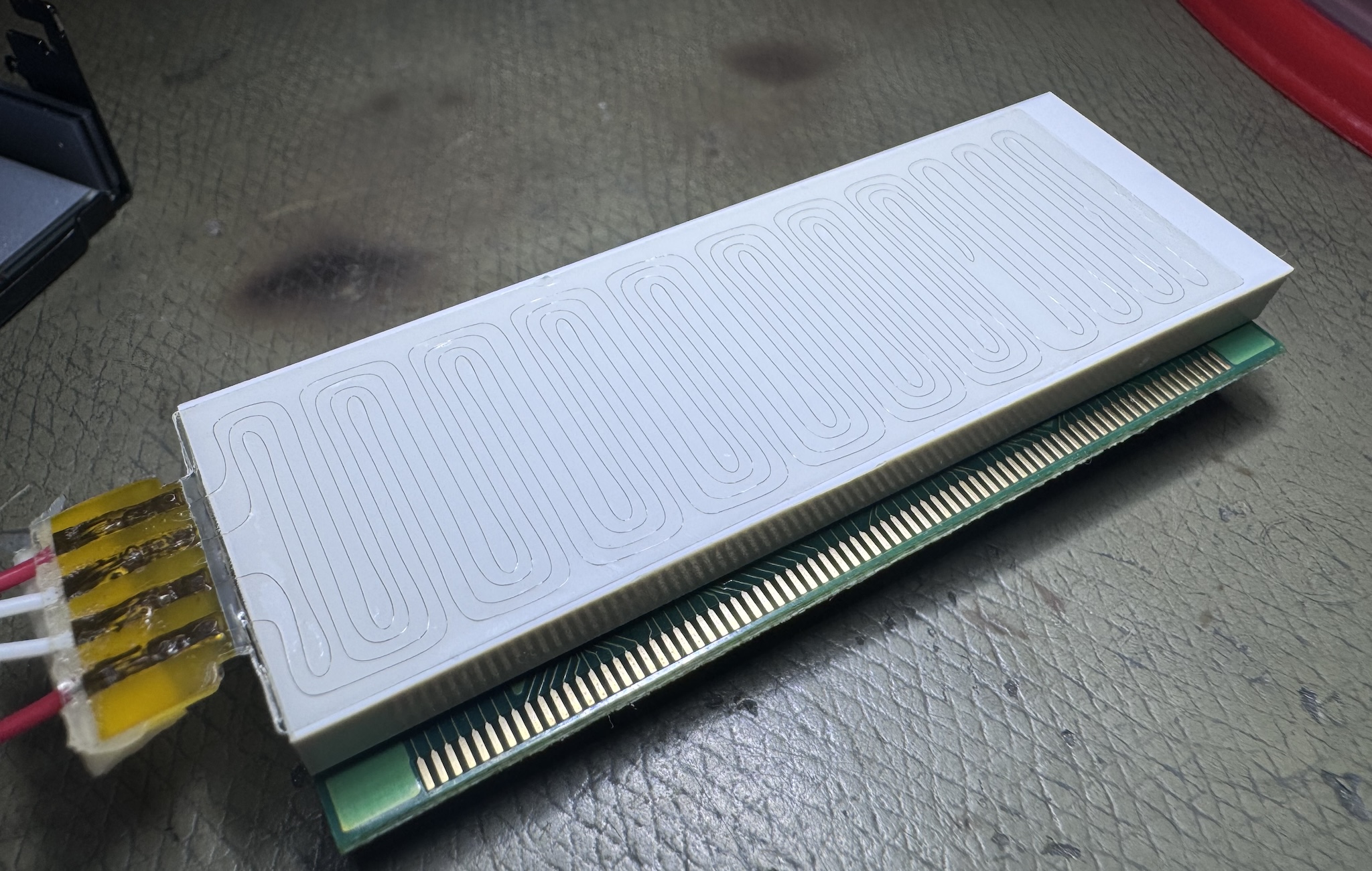
The two red lines measure approximately 470 Ω, and the two white ones measure around 290 Ω. Given their location immediately behind the LCD, this would seem to be an LCD-heater. Probably intended to keep the LCD working well across the whole temperature range.
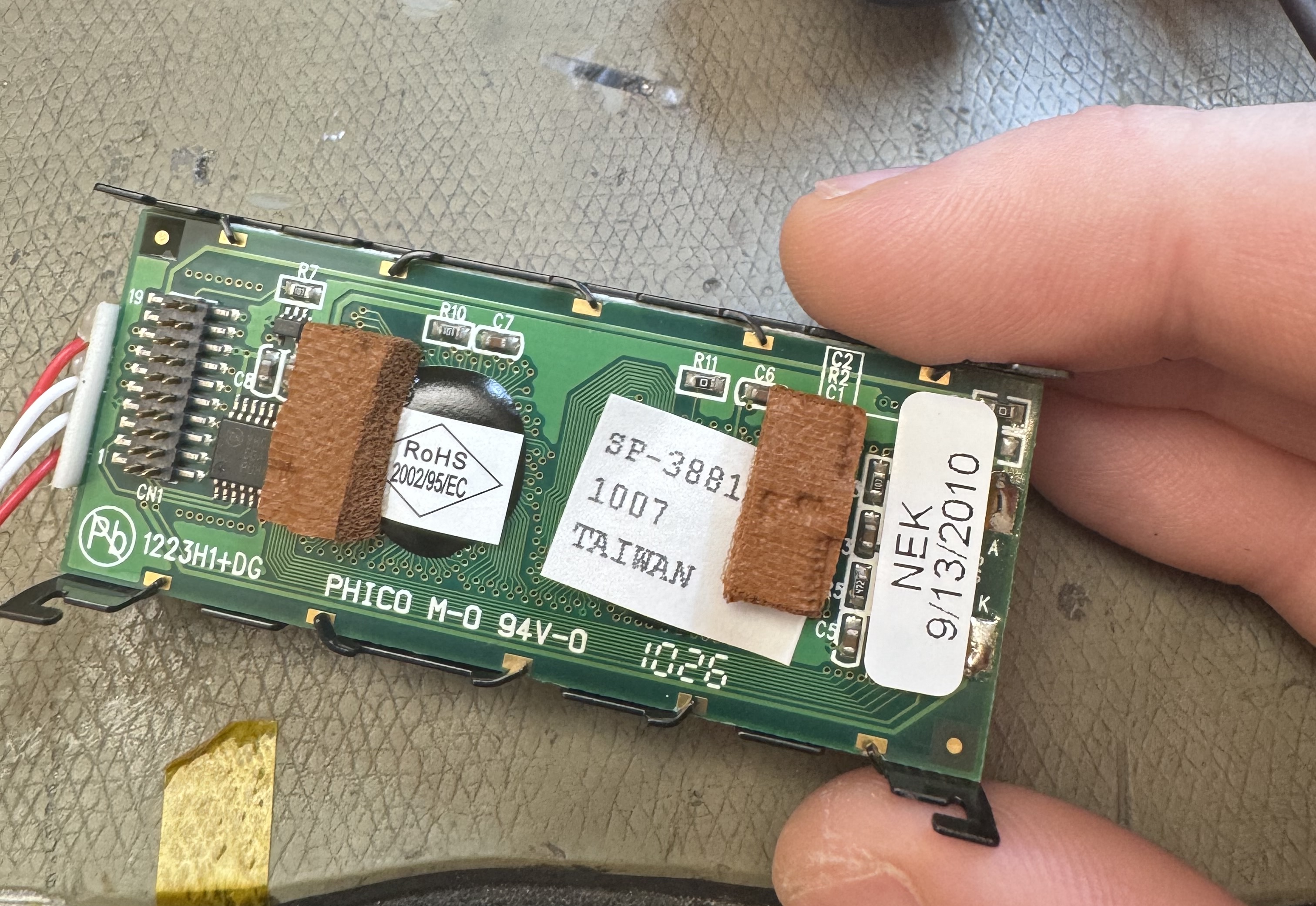
The part number seems to be 1223H1+DG, which leads to a couple of places. The 1223 part suggests this may be a 122x32 display, and given the age of the design it's likely to be built as two 122x16 strips with a separate controller. There is a 3.3 V logic to 5 V buffer on the LCD, meaning 3.3 V logic can be used to drive the control lines, but the data bus is 5 V. A bidirectional level shifter is used to convert between the levels in both directions.
The OEM seems to be Phico, and the closest datasheet I could find is the Pacific Devices 12232-10. This indicates that a SED1520 controller is used.
Having acquired additional KDU's, another variant of the LCD was found as well. The different modules are form-fit-function compatible, but seem to my eyes to have slightly worse contrast than the older Phico unit. On the other hand, the backlight is slightly brighter and more uniform.
A probe around the LCD module and board suggests that the pinout listed in that datasheet is applicable here too. Do note that the pin markings on the controller board are mirrored vs. the LCD markings, I used the LCD markings as my reference.
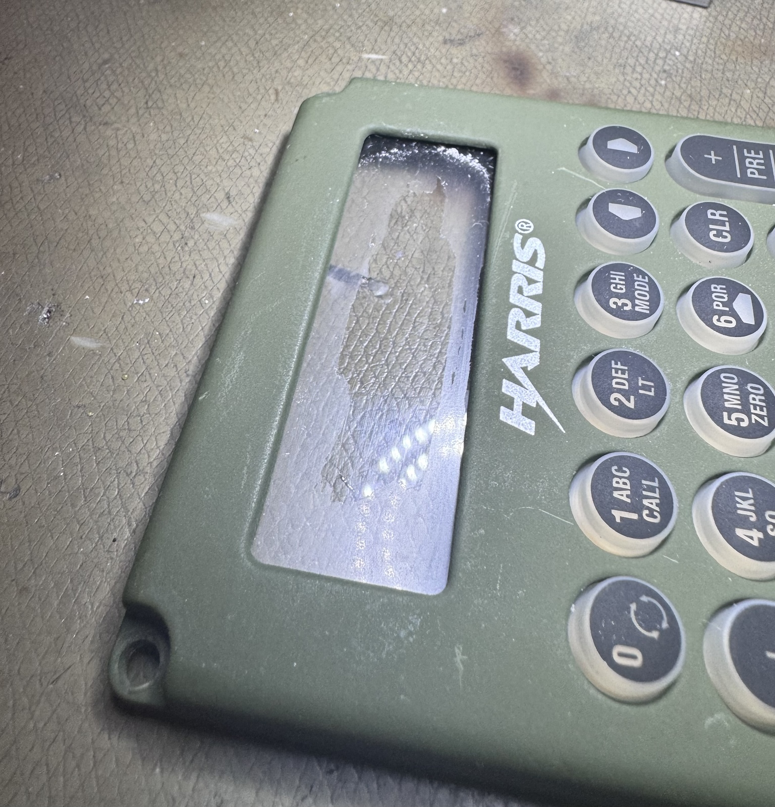
The LCD cover glass has some type of plastic coating on it that is solvable in isopropanol, on some of the units this was annoyingly opaque and reduced the apparent contrast of the LCD in indoor environments.
The plastic coating will be severely fogged if exposed to isopropyl alcohol (and probably acetone). Naphtha based brake-cleaner did not seem to affect it.
I removed it and found that the visual quality of the slightly worse performing newer LCD's was improved. This coating may be intended to reduce specular glare?
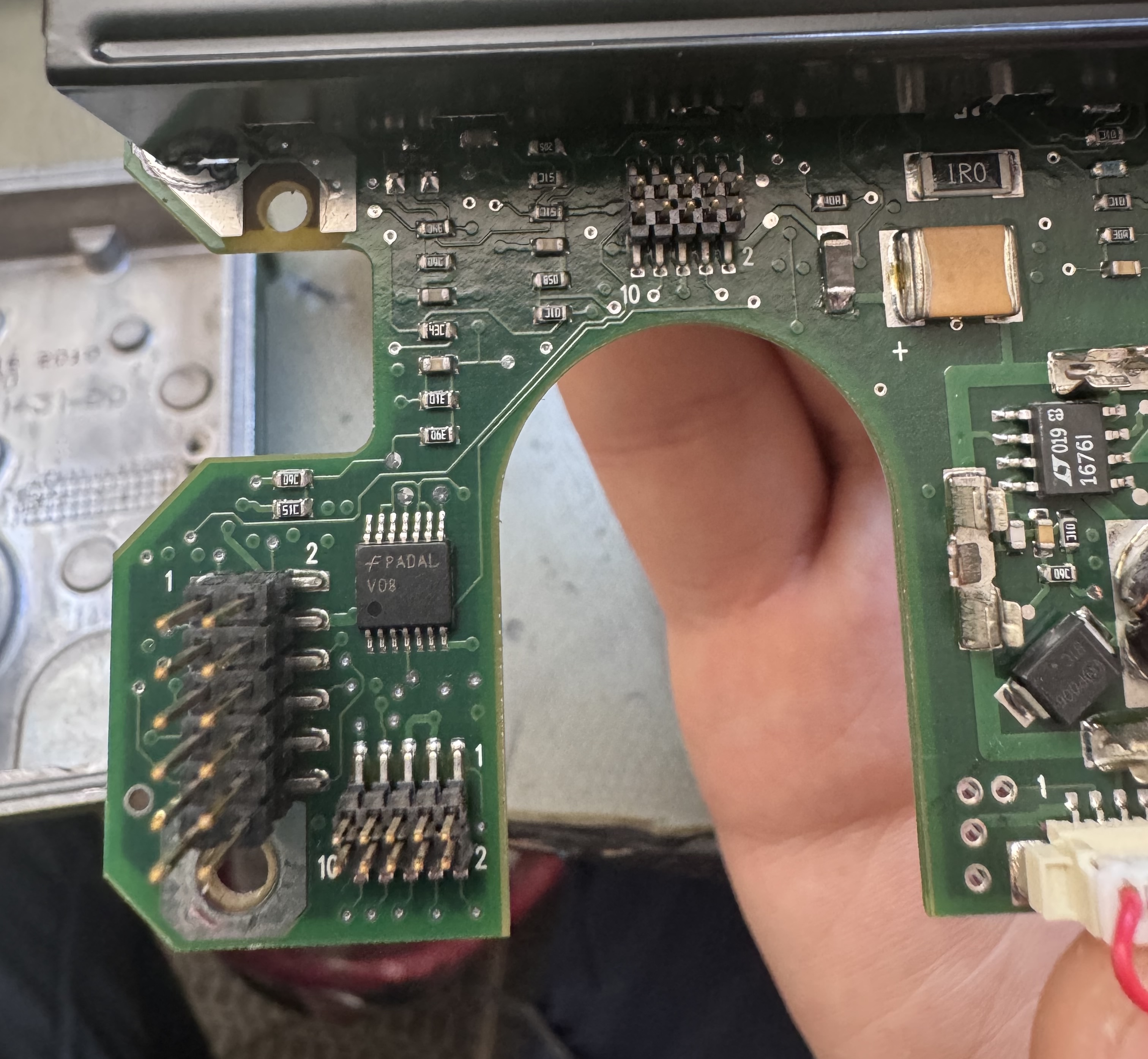
PRC-152 Adapter
The PRC-152 adapter is a pretty complex flex & PCB assembly.
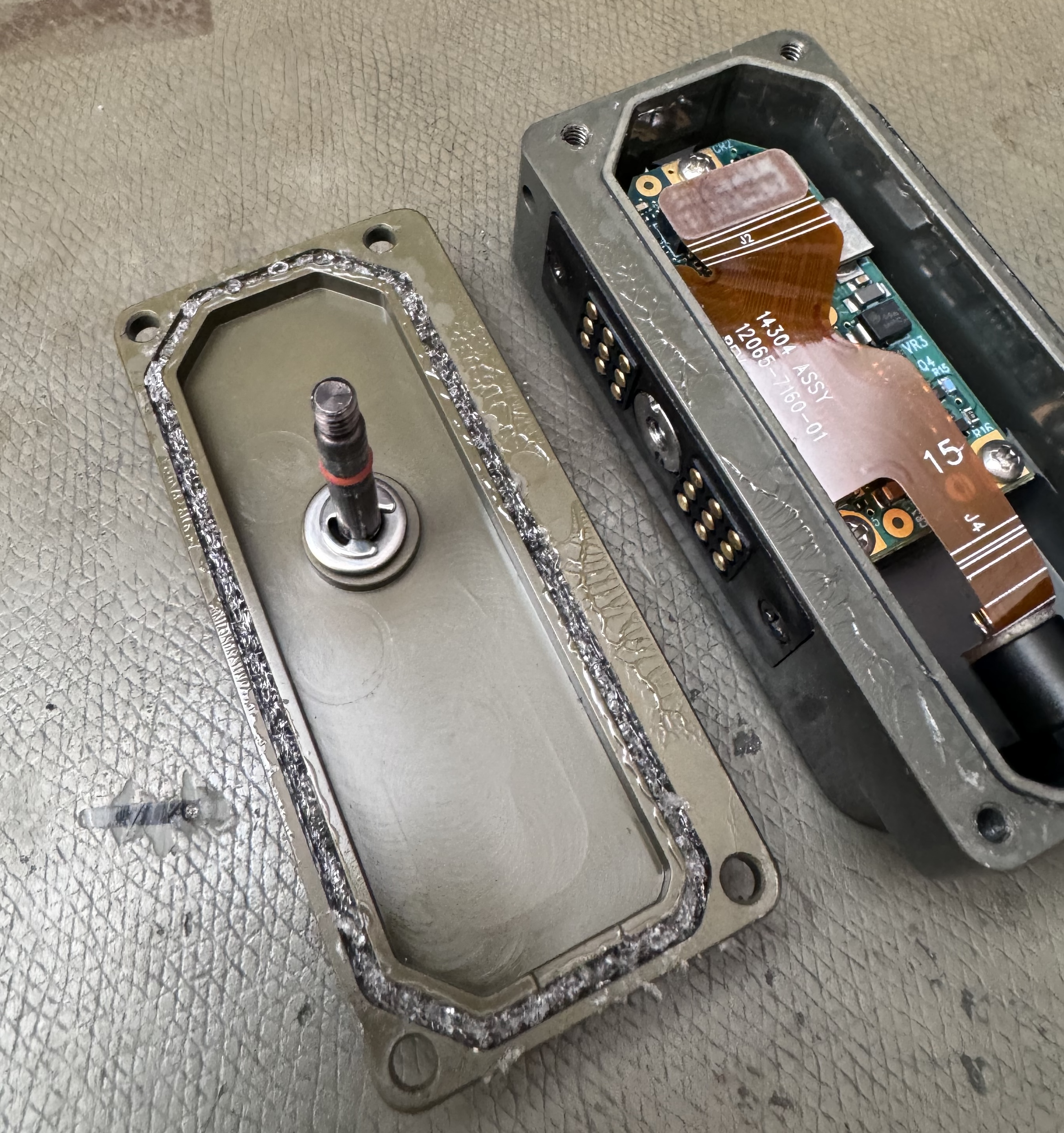
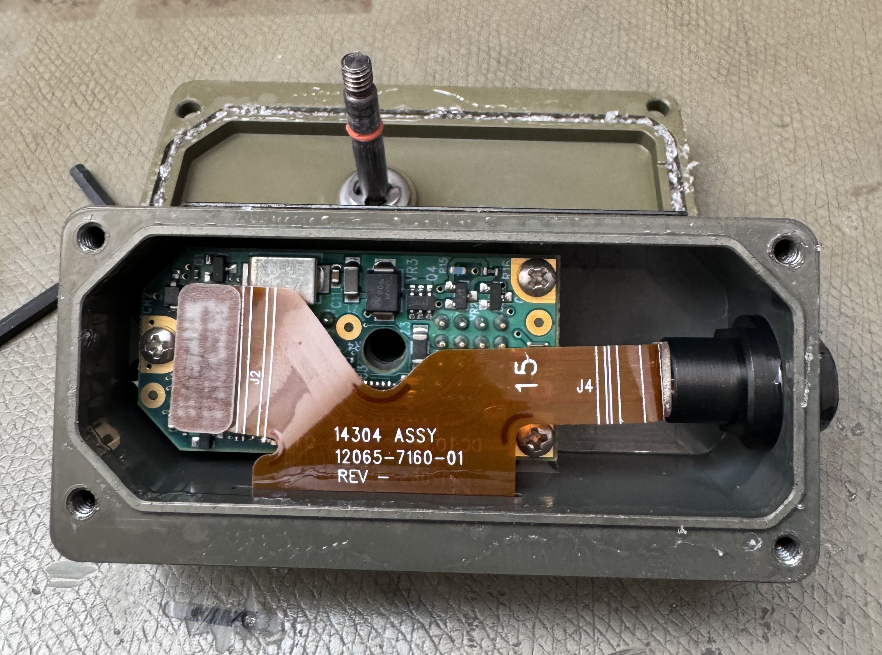
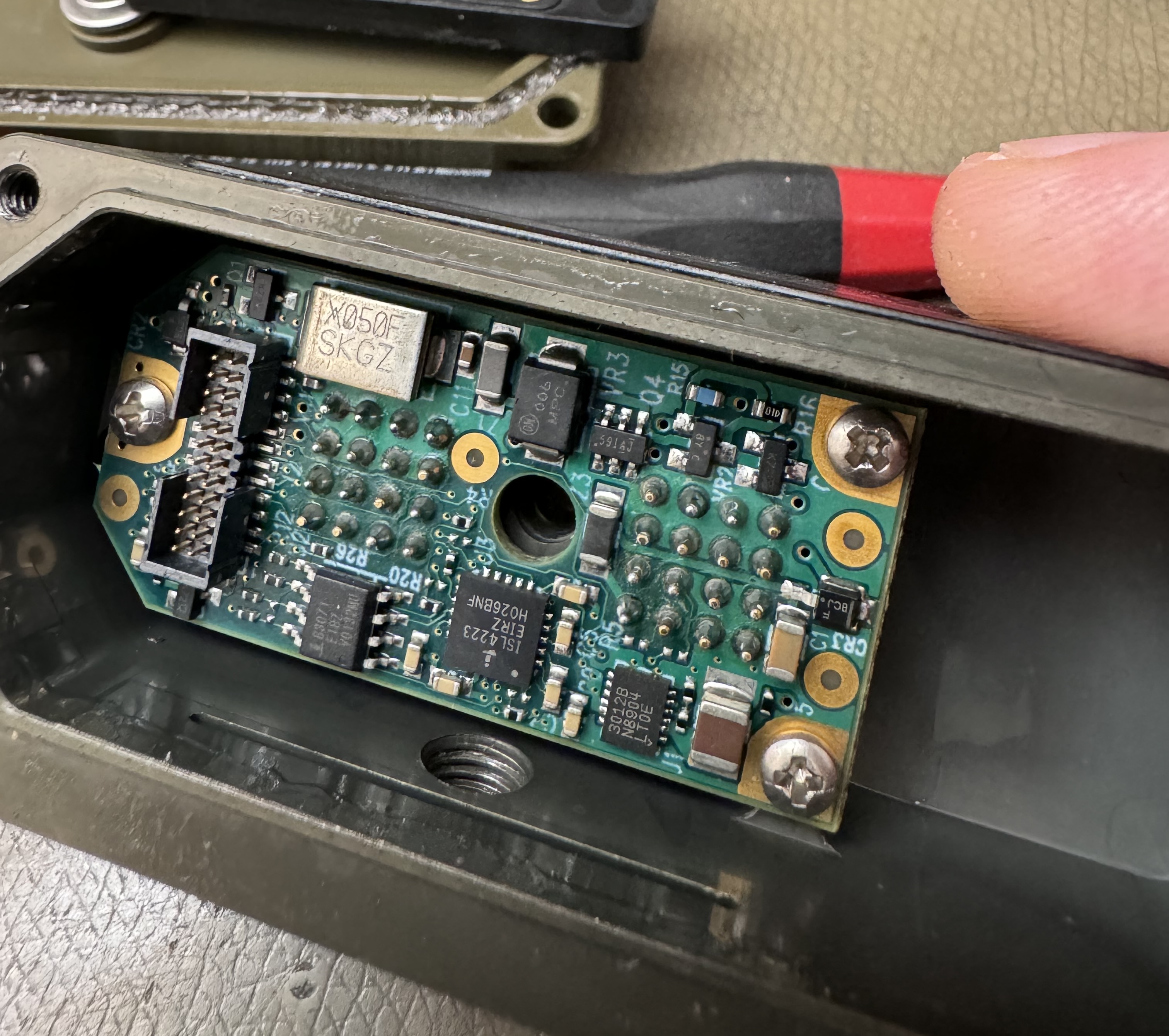
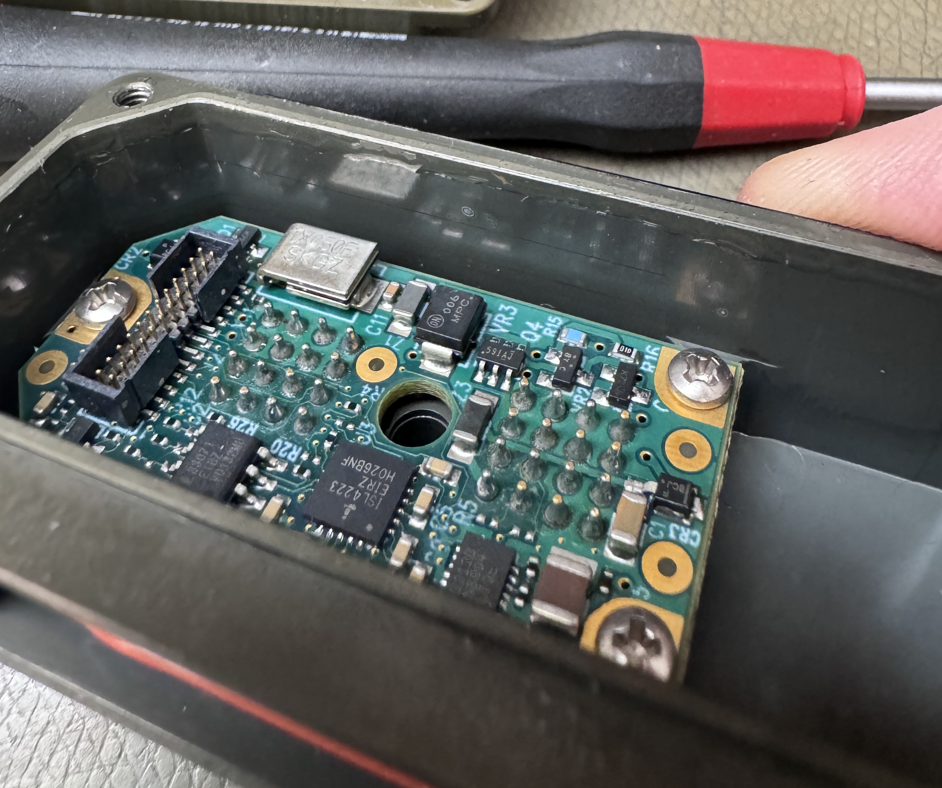
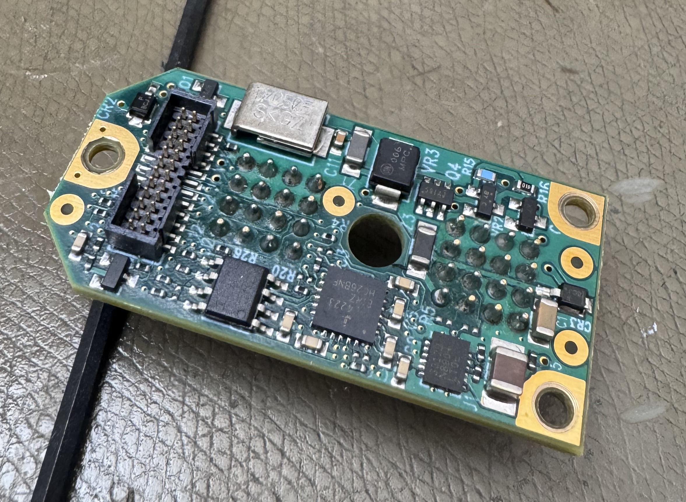
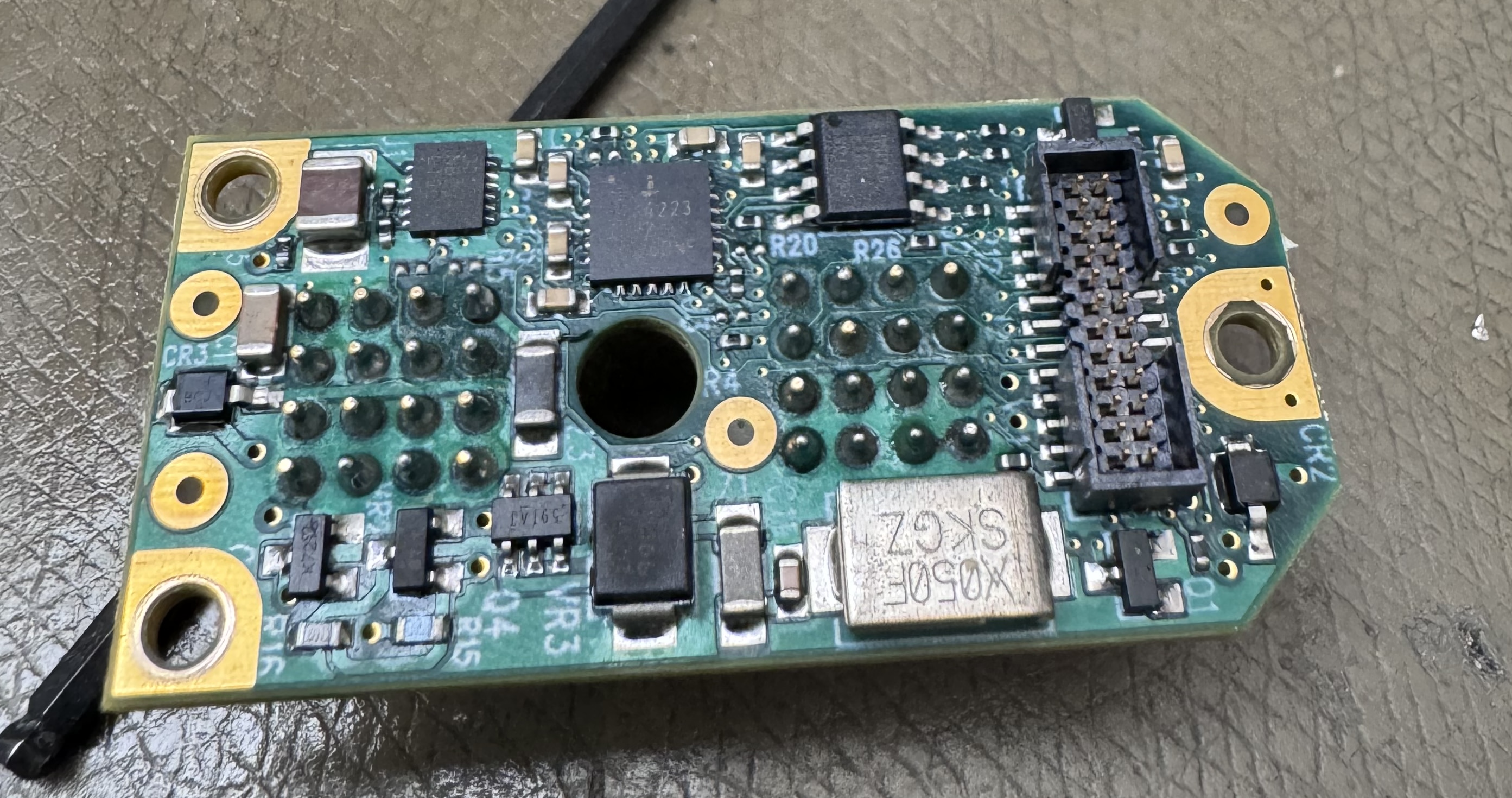
It contains a ISL4223 dual TTL-RS232 converter, and a ISL83071E full-duplex RS-422 transceiver. One set of the 4223 is presumably converting RS-232 from the PRC-152 to the RS-422 that the KDU wants. The function of the other set of RS-232 transceivers is not known at this time.
It also has a LT3012B linear regulator presumably making the logic supply for the serial converters, and some type of mystery-IC marked 59IAJ or 591AJ that looks like it's wired as a boost converter with a 4 µH inductor. The latter presumably makes the 26.5 V that the KDU wants from the radios ~12 V battery supply.
The ODU connector used in this adapter can be harvested for use on the rear port of the KDU.
The PCB markings around the 2⨉16 pad PRC-152 connector does give a somewhat authoritative reference for the pad numbering, seemingly starting at the bottom left of the radio port at pin 1, counting to the right and returning to the left for pin 5.
There are several transistors and diodes around the place, a lot of these are probably for protection, but it seems the main function of the device is to convert RS-232 signals from the PRC-152 to RS-422 signals for the KDU, and to boost the battery voltage to 26.5 V.
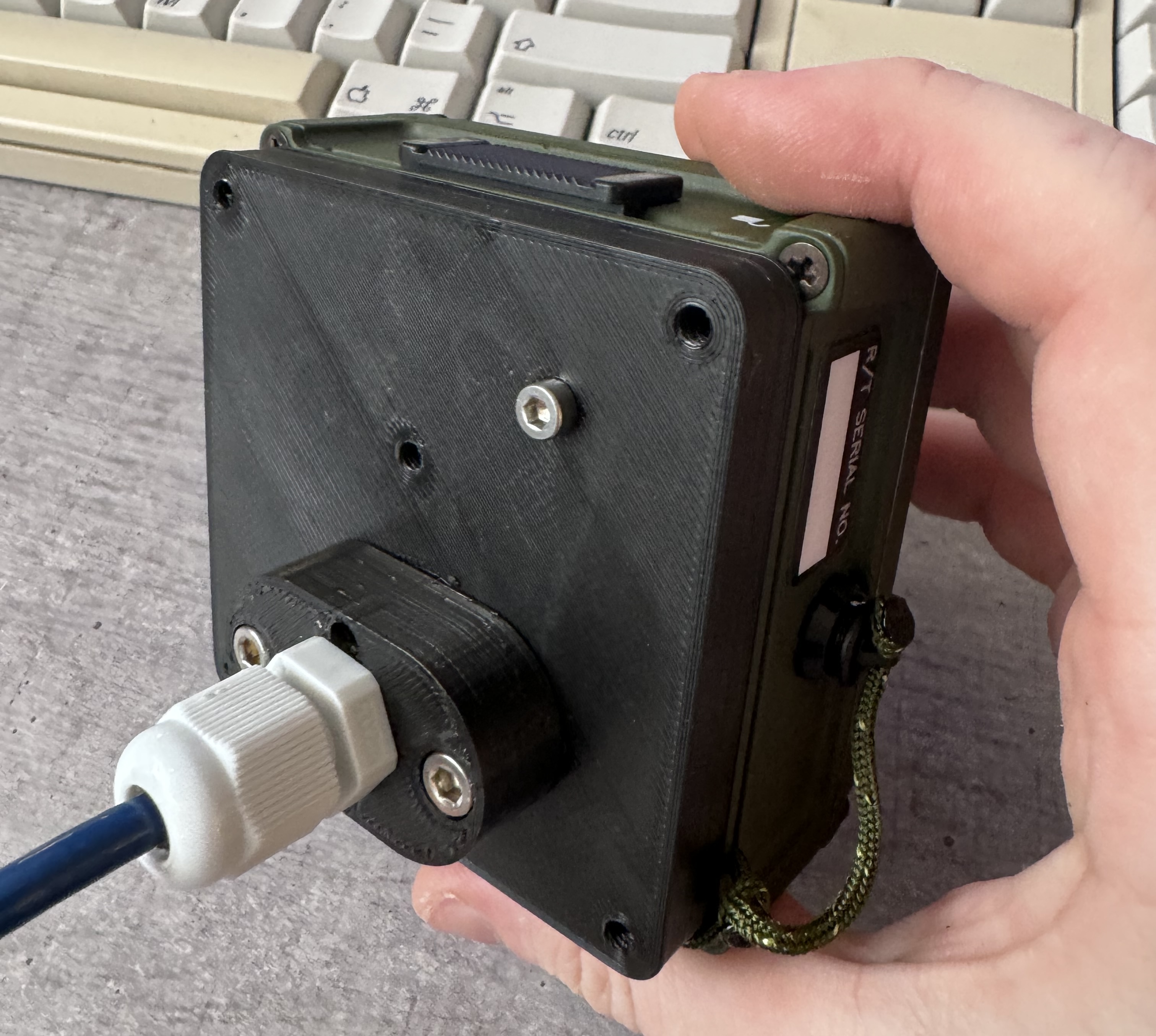
KDU Mount
A simple mount has been modelled for your convenience, it can be 3D printed as required, I used PETG.
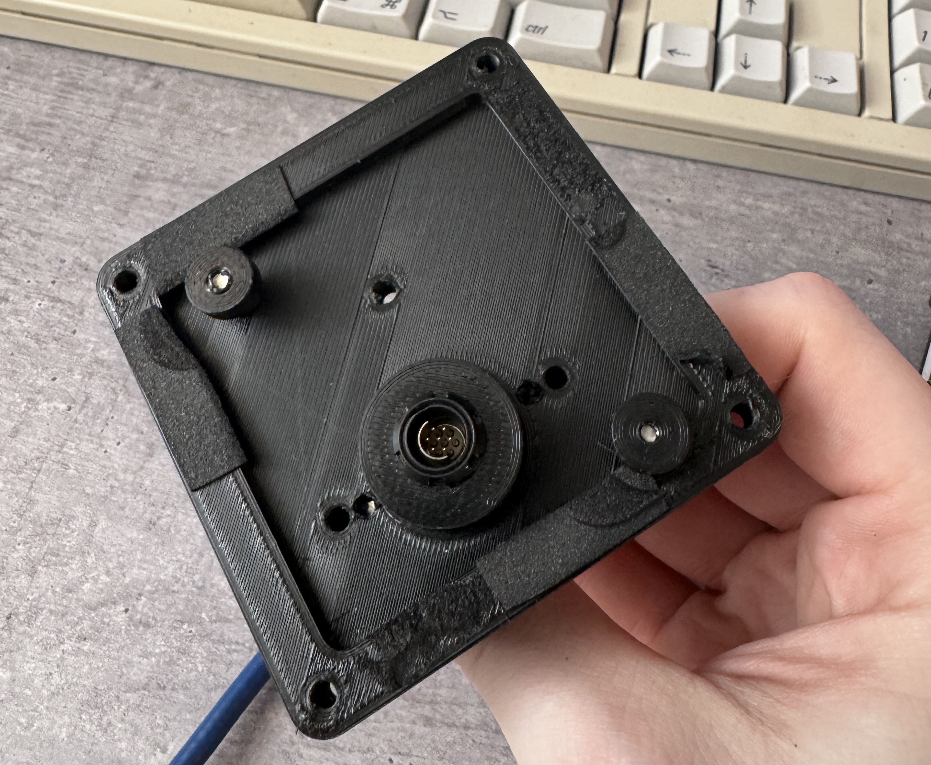
It's not a complex design, and is printed in several parts and screwed together, this allows for ease of design iteration but could perhaps be optimised for parts count. I also made an attempt at making drawings.
Download here: FCII_Mount_v1.zip
It also requires some screws, all DIN912 spec:
- 2 pcs M2⨉10 for mounting the Connector_Adapter to the Connector_M12 block
- 6 pcs M4⨉16 for mounting the M12 block to the Block, and for screwing on the stands
- 6 pcs M3⨉16 for screwing on the support posts and pins
- 1 pcs M12⨉1.5 mm cable gland or similar to hold the cable
You will likely also need taps for M3, M4, and M12x1.5 to clean up the holes. The M2 holes are fine to just screw right in. I found going slow and using lubricant is a good idea for PETG, most taps get pretty warm tapping it and eventually it can start to melt the plastics instead of cutting them.
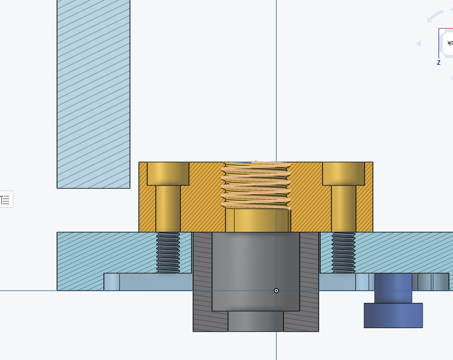
Above the light blue Block (main body) is shown, with a darker blue Pin part. The Pin (2 pcs) mates with the hole-sliders on the KDU. The Pins are retained using M3 screws, and are deliberately slightly long.
I place 1 mm thick foam along the sides to provide a cushion (spring), and the tightness of the pin screws can be used to fine tune the fit.
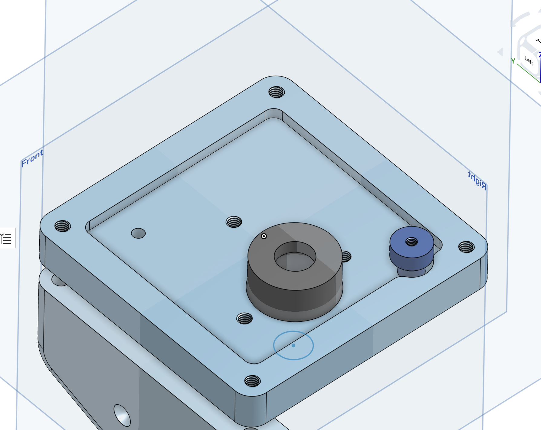
Above the interface for reusing the PRC-152 connector is shown, it has two parts, an "Adapter" that the ODU connector is screwed into (grey) and a M12 block that screws into the main Block.
There is no rotation indexing for the ODU connector, so the rotation is set by the front nut for the connector — I installed it hand tight, then rotated it into alignment using the connector block when mated, then went back and tightened the nut a bit more. It's a bit fiddly. Be careful installing the cable gland to prevent rotating the wire.
Additionally, some at present untested feet may hold the KDU at a reasonable angle for desk mounting, with flats for taping or M4 screw holes for screw mounting. Some 50 mm long M3 posts are used to provide sideways stability (also untested).
Future Work
As mentioned above, I plan to dump the ROM of the KDU to see if I can work out the command interface. This would make it quite practical to repurpose these displays for hobbyist projects or to control other existing radios. I decided to replace the internal electronics, see Devlog 2.
I am working on my own heavily modified TRI AN/PRC-152 and had planned on making the PRC-152 adapter compatible as is, but I have decided to re-make the adapter since this will let me freely use my own pinout.