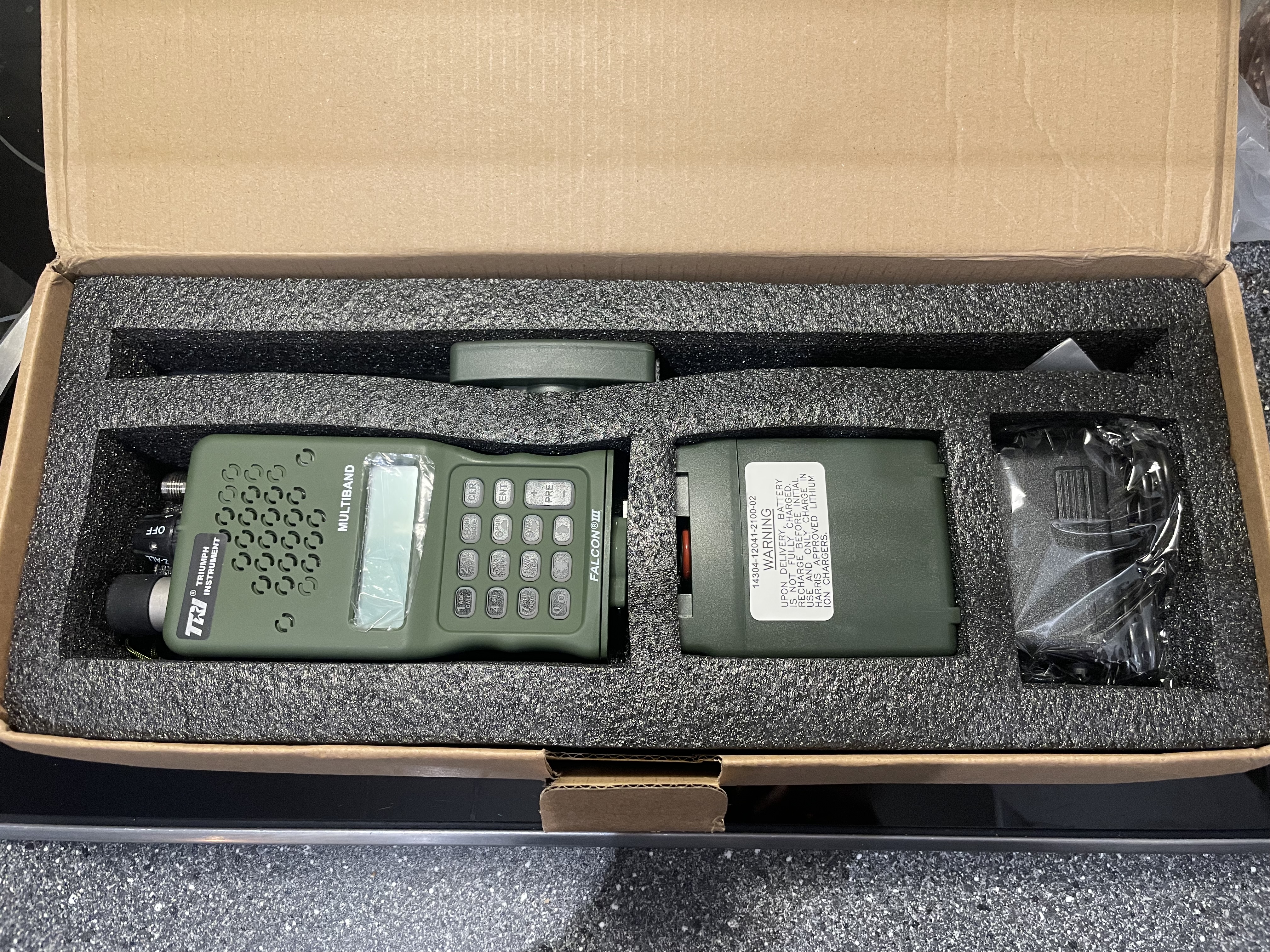
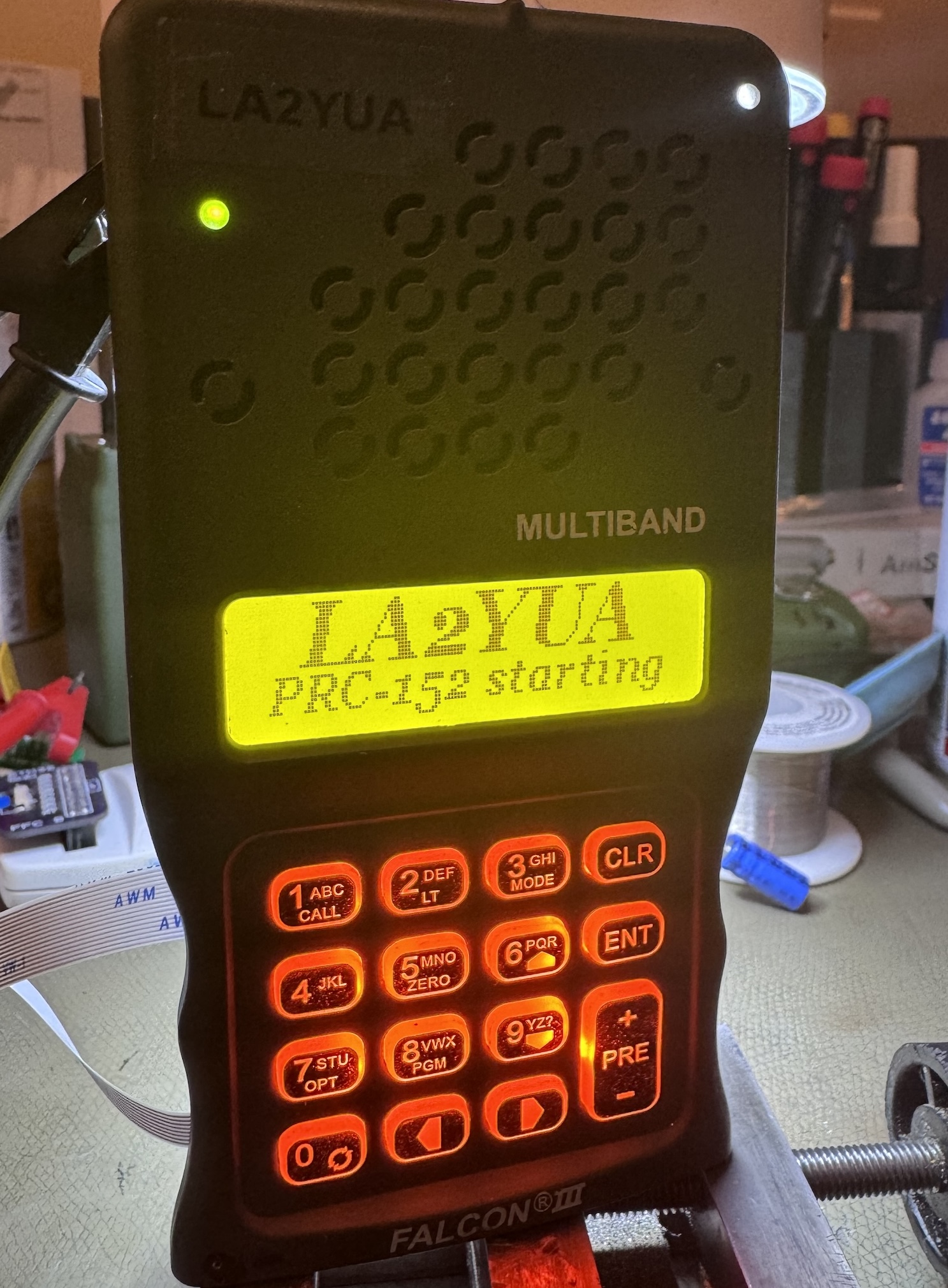
TRI AN/PRC-152 (2022/2023 model)

The TRI(iumph Industries) AN/PRC-152 two way radio is at first glance a rather silly device, a clone of the extremely capable and expensive Harris AN/PRC-152 (Falcon III) software defined hand held radio.
Is it worth the money at all?
Table of Contents
Introduction
TRI is a fairly well known name in some circles, the company seems to have very limited direct presence with no English language web site. They seem to have found a niche in catering primarily to the airsoft/mil-a-boo crowd, a market that generally favours authentic-looking military replicas including for their communications solutions.
The TRI 152 is certainly polarising in the ham radio world, and looking at various forums we generally find a few different groupings which I'll summarise as:
- ”it's for fucking plebs that can't afford the real thing”
- ”it's probably shit for airsoft weebs”
- ”I used the real thing in —insert country here— and the real deal was shit too”
- ”I bought one and it's cool”
- ”—various racist remarks on Chinese manufacturing—”
I will admit to having a certain attraction to the military æsthetic, and so I ordered one to try out. Shipping took a while, I was informed by the seller that the delay was due to this being the latest production batch directly from the factory.
It is worth noting that these radios exist in various variants, with some differences in features. TAC-sky is another manufacturer of a seemingly very similar device, that model seems to include a GPS receiver as well.
Pre-2022 models of the radio seem to have a more limited feature set. The first issue of this radio from memory popped up around 2017, and seemed to essentially be a Baofeng UV-5R radio in every way.
Specifications
The basic listed specifications are:
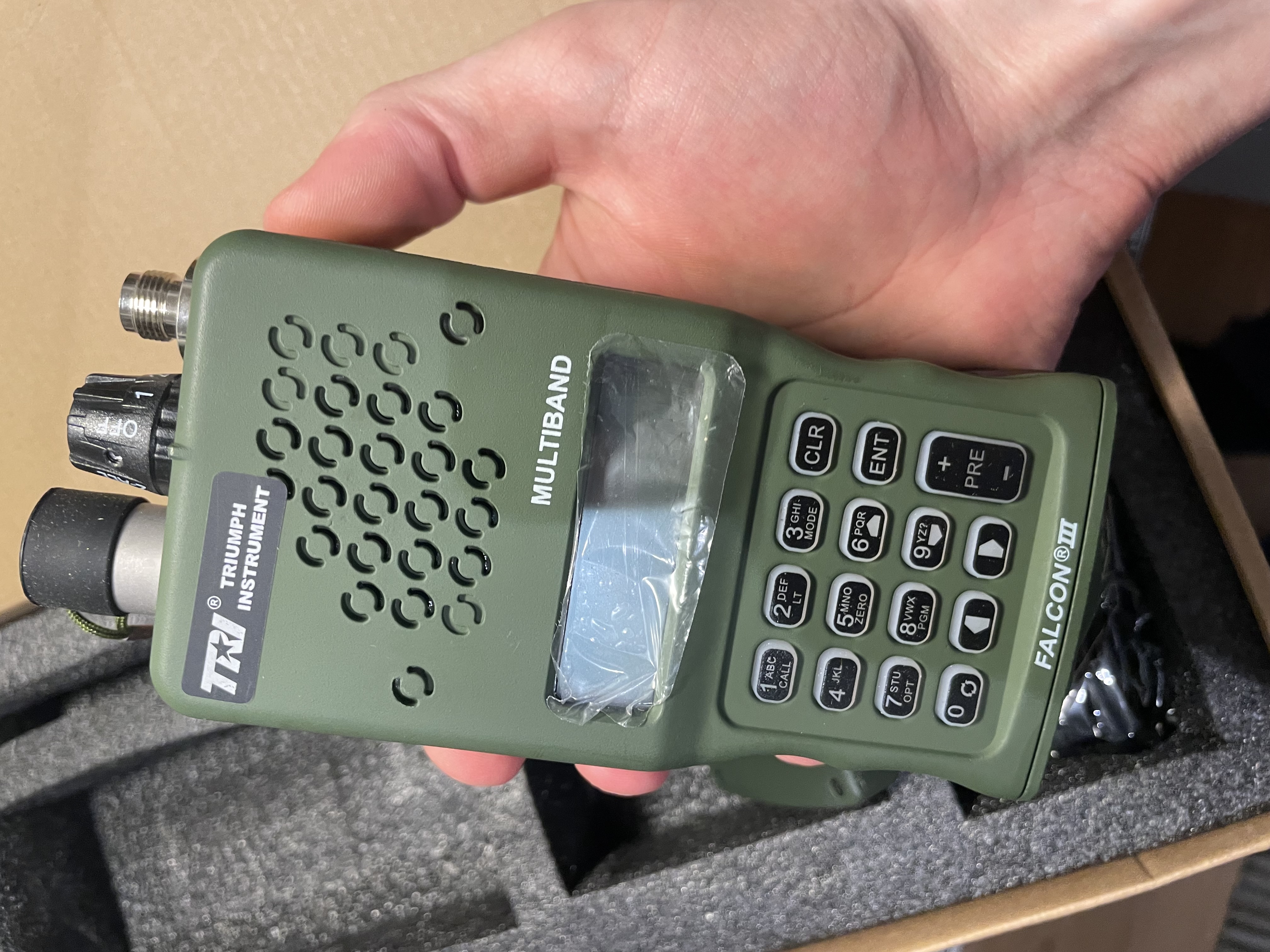
- Aluminium shell, æsthetic replica of the Harris product
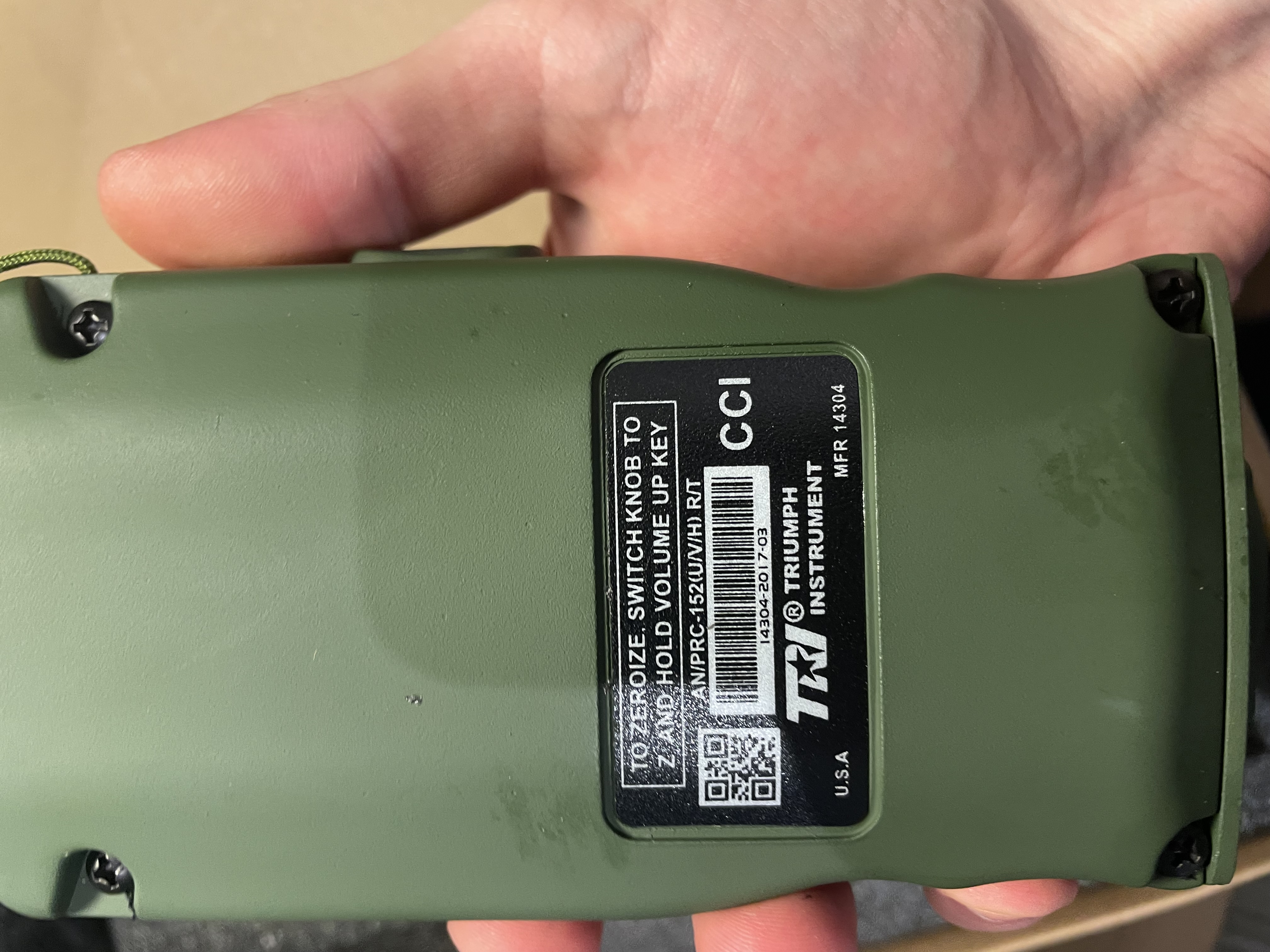
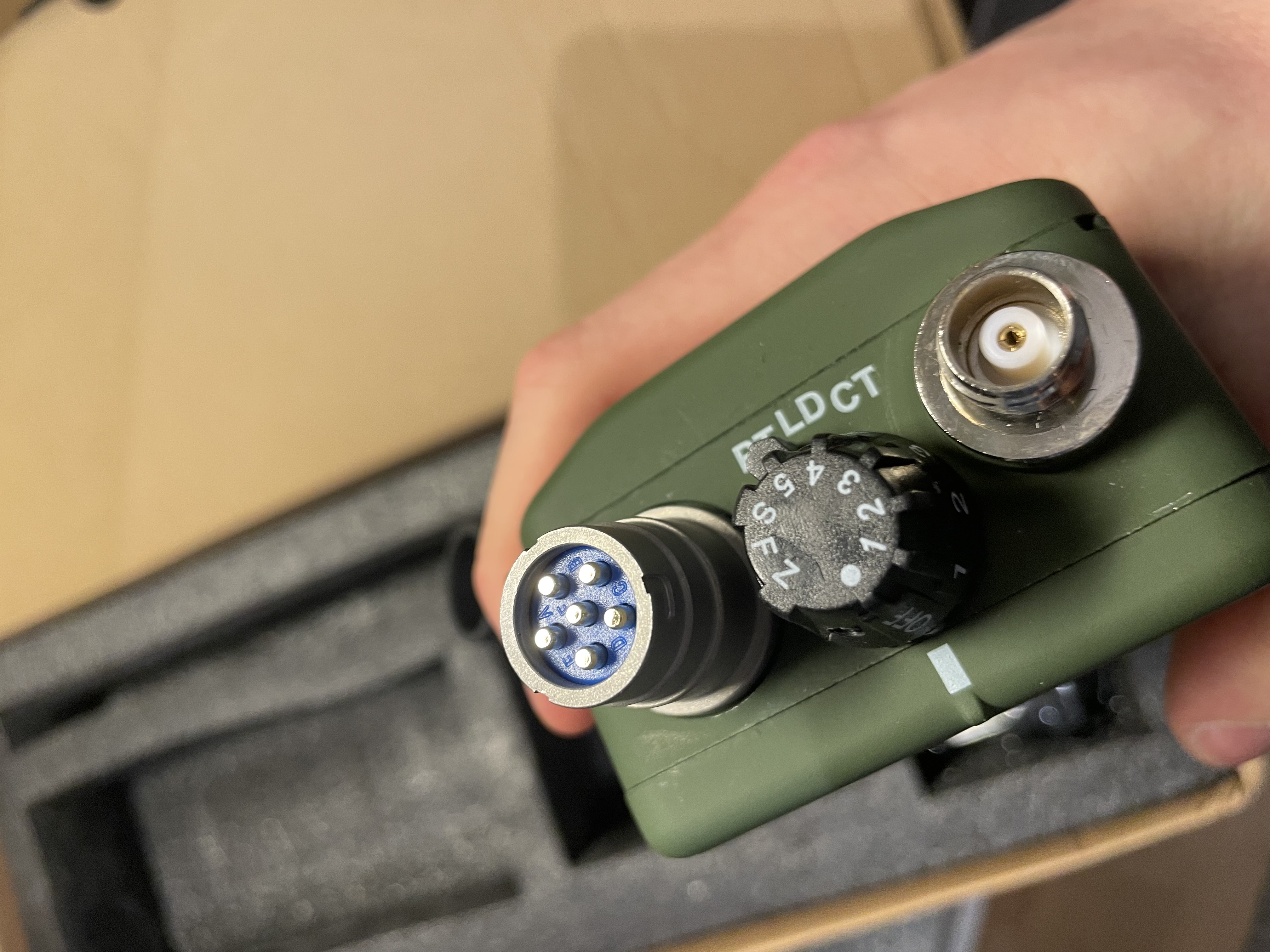
- Compatible with e.g. H-250 handsets, dynamic or electret microphones supported (MIL-DTL-55116 6 pin handset connector; 5 pin compatible)
- Compatible with genuine Harris batteries and antennas
- One battery option is a 6-cell 12 V (3S) case that can be fitted with 6 18650 cells
- Transmit/receive coverage 136-174 and 400-480 MHz at 15 W power, standard narrow-band FM
- Limited power in the 220 (220-259) and 350 (330-370) MHz bands
- (The Harris device covers approximately 30-512 MHz with software defined modulation types)
- Broadcast FM and Air-band AM reception
- Dual receiver (implied to be a true double receiver, not just a scanner)
- Cross-band repeater support
- Speech compander & encryption (assumed to be a basic spectral inversion type)
- Support for an external wrist-mounted external control unit (KDU)
The TRI variant does not seem to support PC-programming, while the TAC variant seems to have a USB-cable that plugs into the U-229 connector. The TAC variant does seem to be slightly different from available pictures, using e.g. a slightly greener LCD backlight vs. the TRI unit.
The biggest question to answer is how does the radio perform, have TRI used the fairly large internal volume and price to stuff in a high performance radio with excellent performance, or did they just put some COTS radio modules in a fancy case and call it good?
Is It Good?
The answer to this question revealed itself pretty quickly when I received it, it's an extremely well made enclosure around what is basically a slightly upgraded standard radio, probably some earlier variant of a Quansheng UV-K5 based on the internals. There are however some nice touches here.
I won't be too hard on it but there are certainly issues that could have been resolved with slightly more engineering and user testing put into it. I'm not sure I'd recommend it unless you go hard on mil-sim.
The biggest issue I had with the radio is simply that the audio quality is not very good and the audio routing system is not very flexible. The original speaker rattles like crazy at even slightly elevated audio levels, and there is a compander-like noise reduction system that seems to make things even worse in most modes.
Further, there is no option to route audio to both the handset and internal speaker, or to auto-switch it. Additionally there is no option to use mic-follows-PTT, so if you set it to external handset mode the internal PTT works, but the handset microphone is used. This may be usable in some configurations but for a handset the microphone is normally switched so no audio is transmitted.
Transmit audio quality with an external H-250 handset was quite poor, with lacking treble and distortion, but receive audio was fine (better than the internal speaker).
The user interface is also somewhat confusing, especially the way air-band and broadcast FM reception is implemented as some kind of transient overlay mode. Also there is no squelch for AM receive, a pretty serious omission.
In general it seems like a fairly standard radio firmware was used (hell, it's likely software-compatible with some other radio). This means the UI doesn't really utilise this radio's user interface options, and things like the keypad arrow markings don't really mean anything.
Cross-band repeat does work, but the repeated audio is severely degraded, most likely due to improper filtering and level adjustment (this could probably be fixed with firmware or minor hardware modifications).
Hardware Overview
I'll skip a software overview, it's a mix of fairly standard two way radio interfacing (similar to Baofeng, Tyt etc.) and slightly confusing additions and one typo. At the time of writing, the original PCB's are spread across various tables anyway.
I took various pictures of the radio while disassembling it:
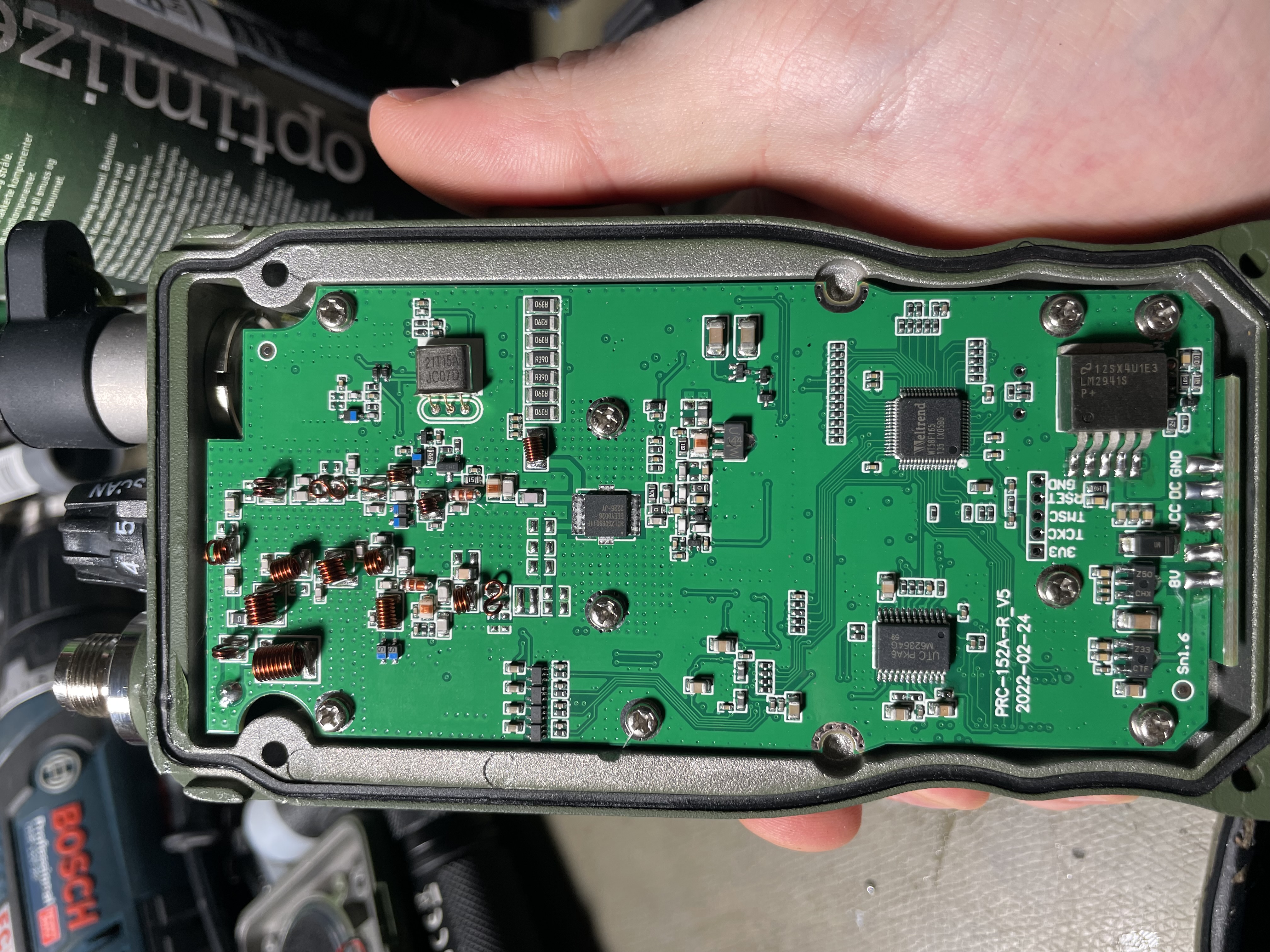
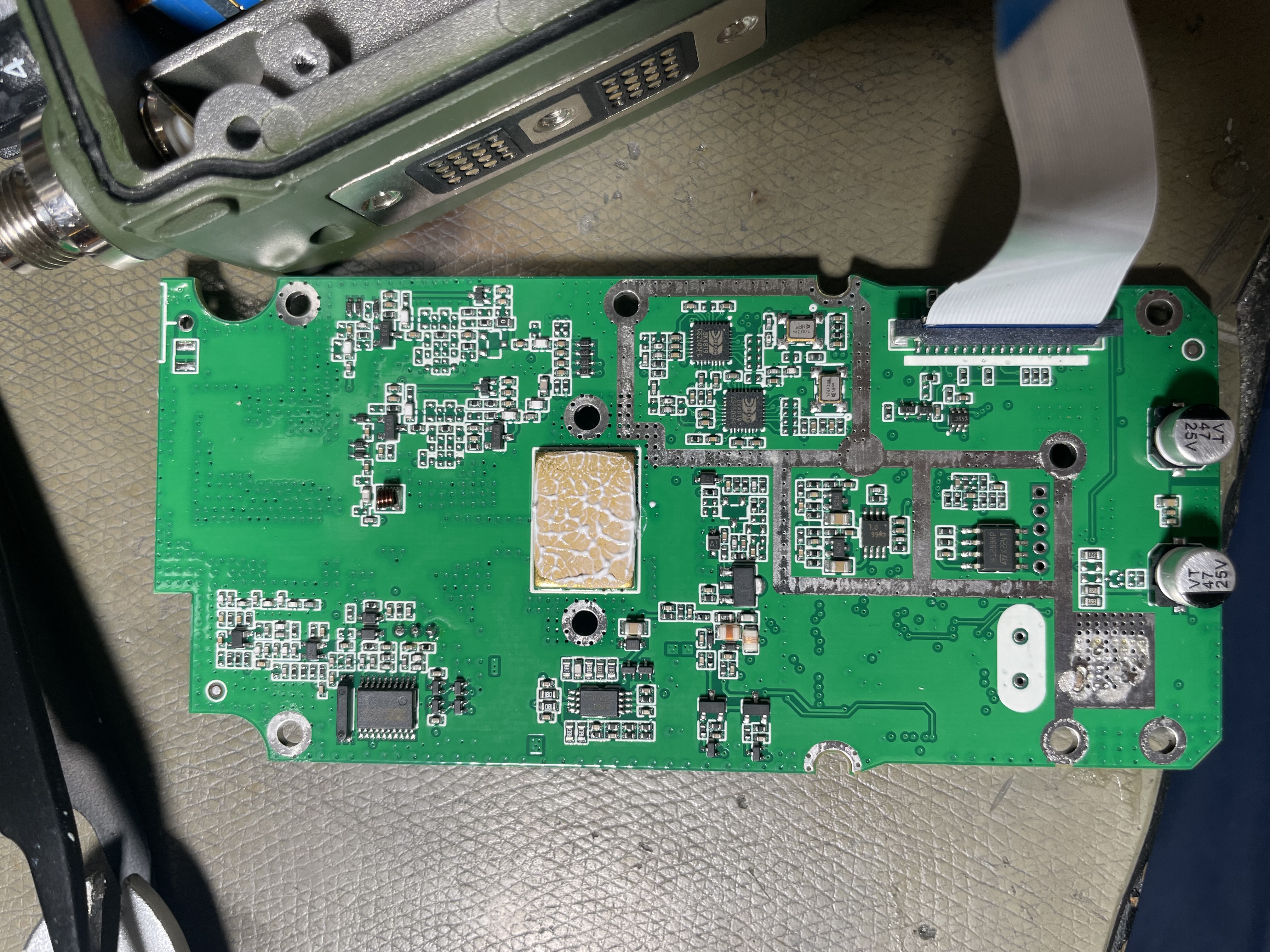
Processor
The main radio processor is a Weltrend WT58F165 ARM processor, a relatively low powered but moderately capable processor for the task of running a basic radio.
Radio Transceiver IC's & PA
The radio includes two transceiver chips, BK4819 by Beken. These are typically used in $20 two way radios, though from what I gather they are considered quite good for their price range. However, this is a $300 radio. I suspect a very large portion of the price went into the mechanical aspects.
Quite recently (during the course of writing this article) a firmware hack was announced for these devices, which could in principle be applied to this radio as well. See https://github.com/Tunas1337/UV-K5-Modded-Firmwares
Additionally, there is a BK1088 broadcast receiver which is presumably used for the FM broadcast reception. This chip is underutilised, being capable of AM and SW reception as well, but only the FM side is used here.
The main PA is common for VHF/UHF, it is a HTL7G06S011P, which is listed as an 11 W PA transistor, but I will note that there is fairly decent heatsinking so running it at ~11 V to give around 15 W is likely not a major issue.
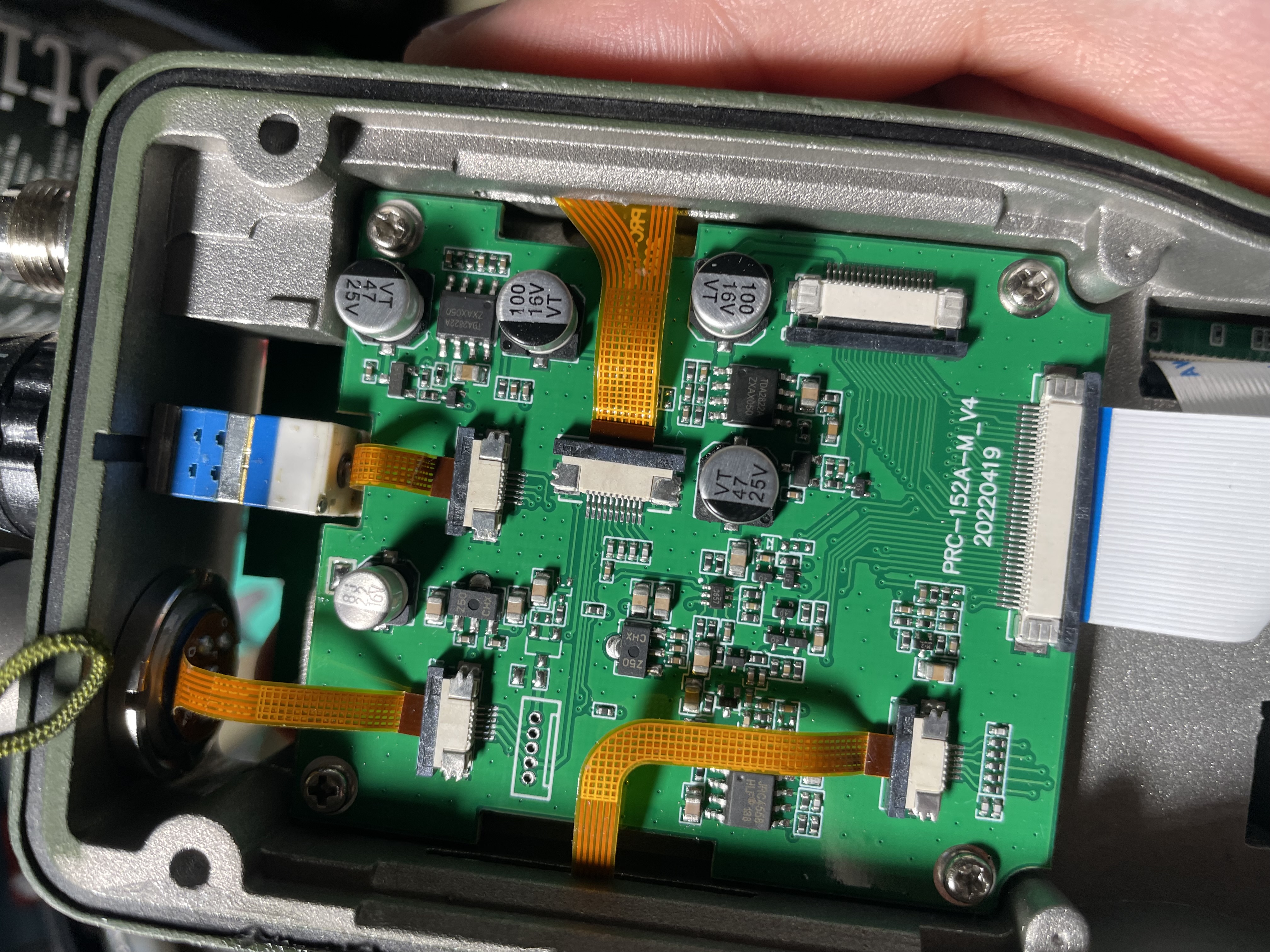
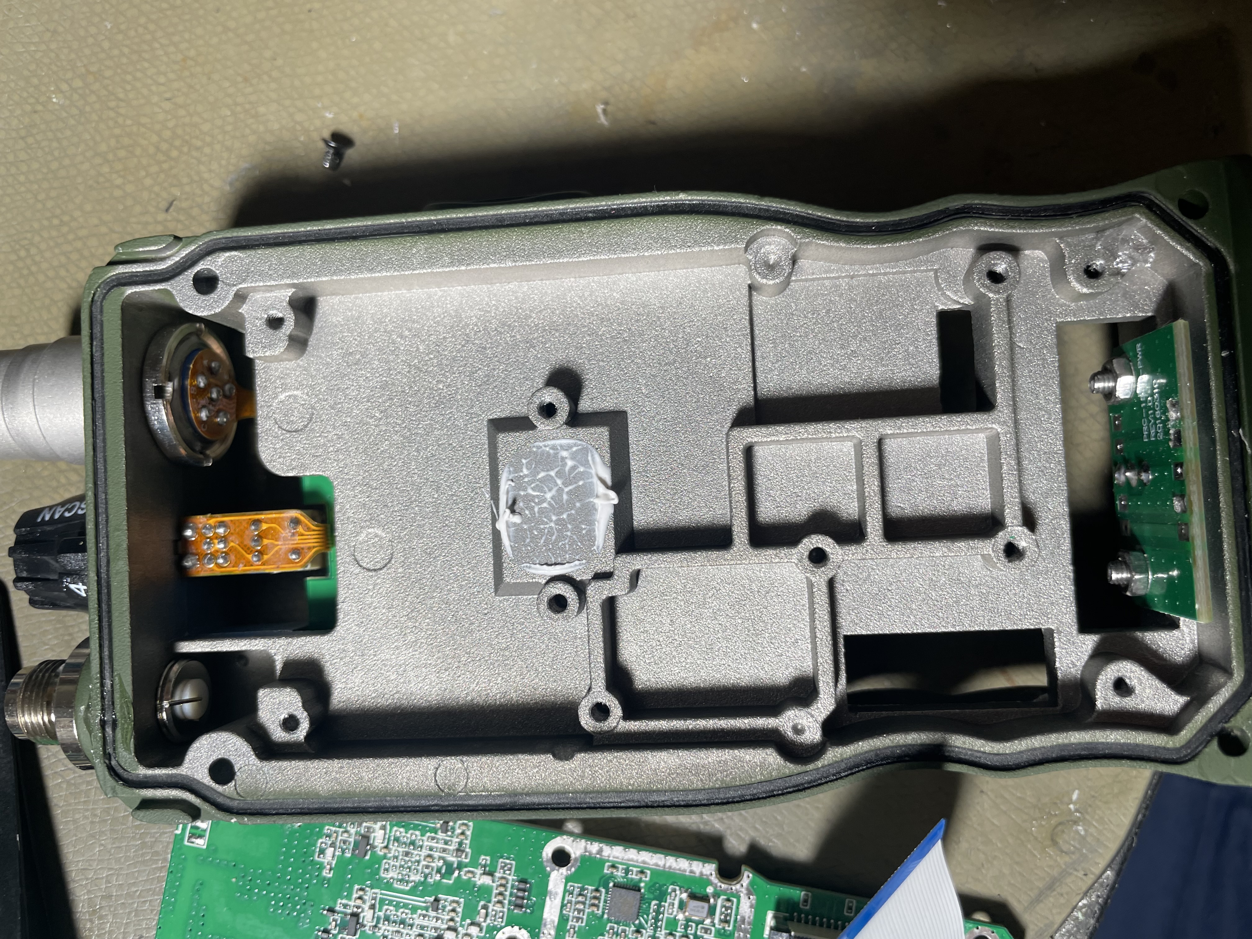
Audio/Interface Board
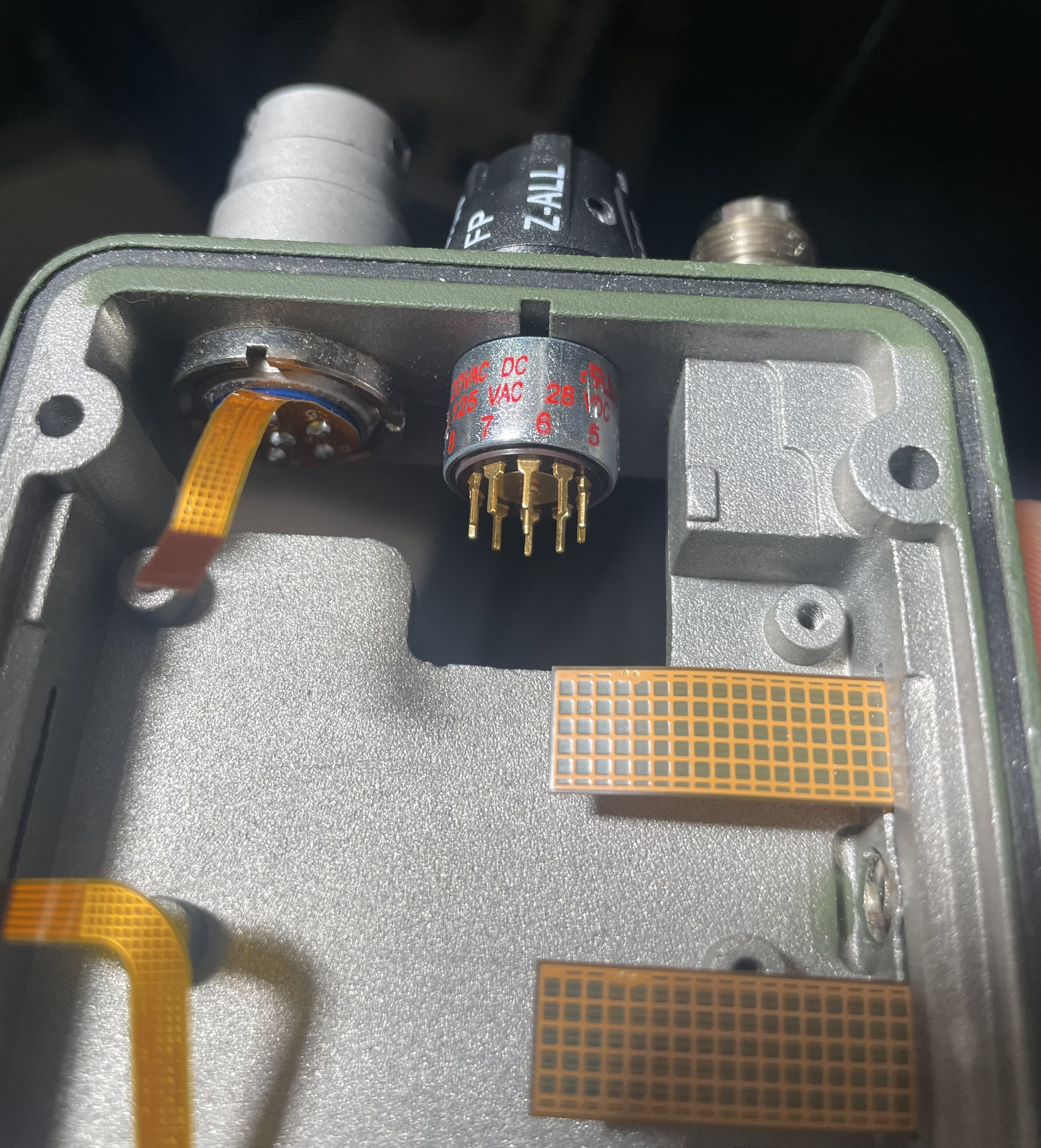
Opposite the RF board is a relatively packed but simple interfacing board which connects to the RF board and provides connections to the audio PA's, microphone preamps, the front panel PCB, side panel PCB, aux connector, volume/AF mode select (top), and the 6 pin handset connector.
Basically every interconnect in the radio is a flex, with several custom flex PCB's made, which does speak to the good build quality.
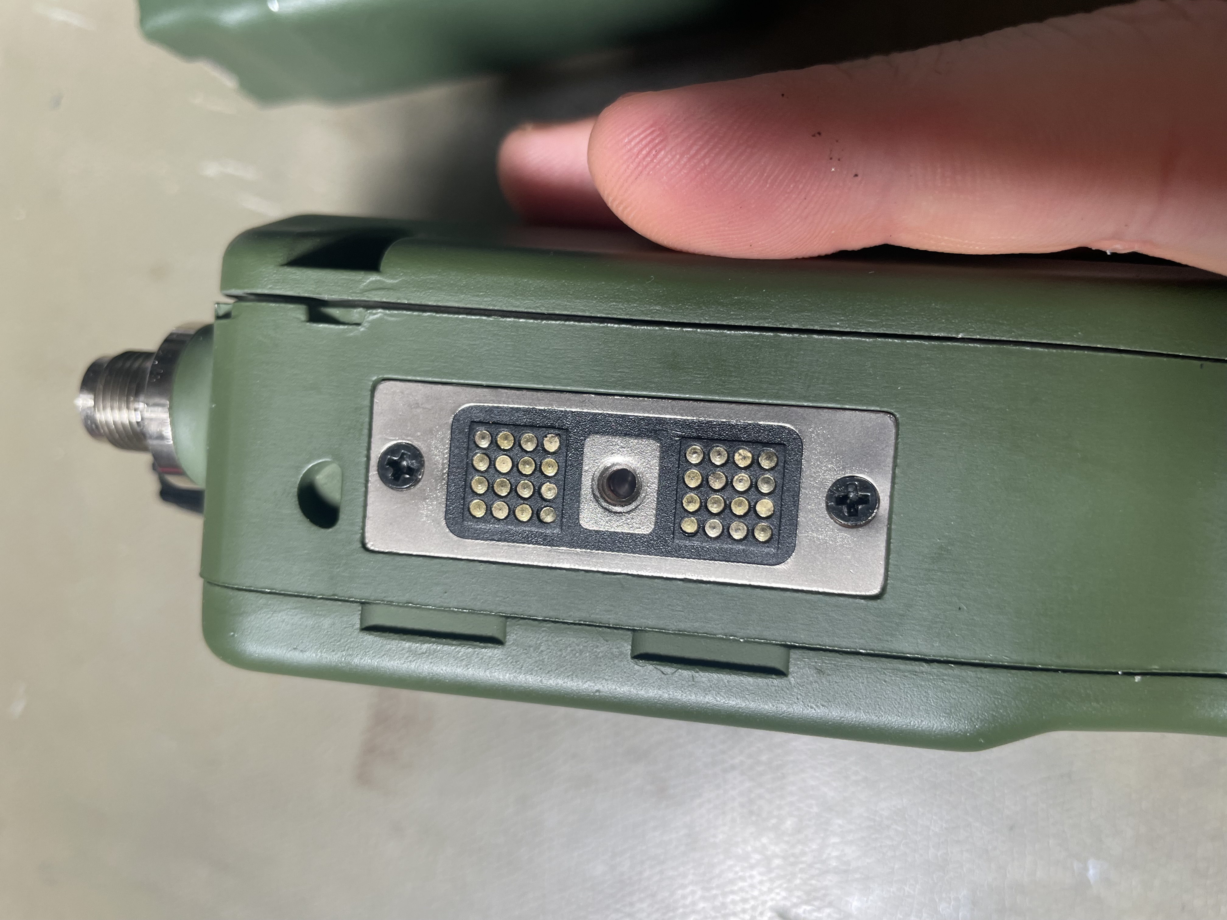
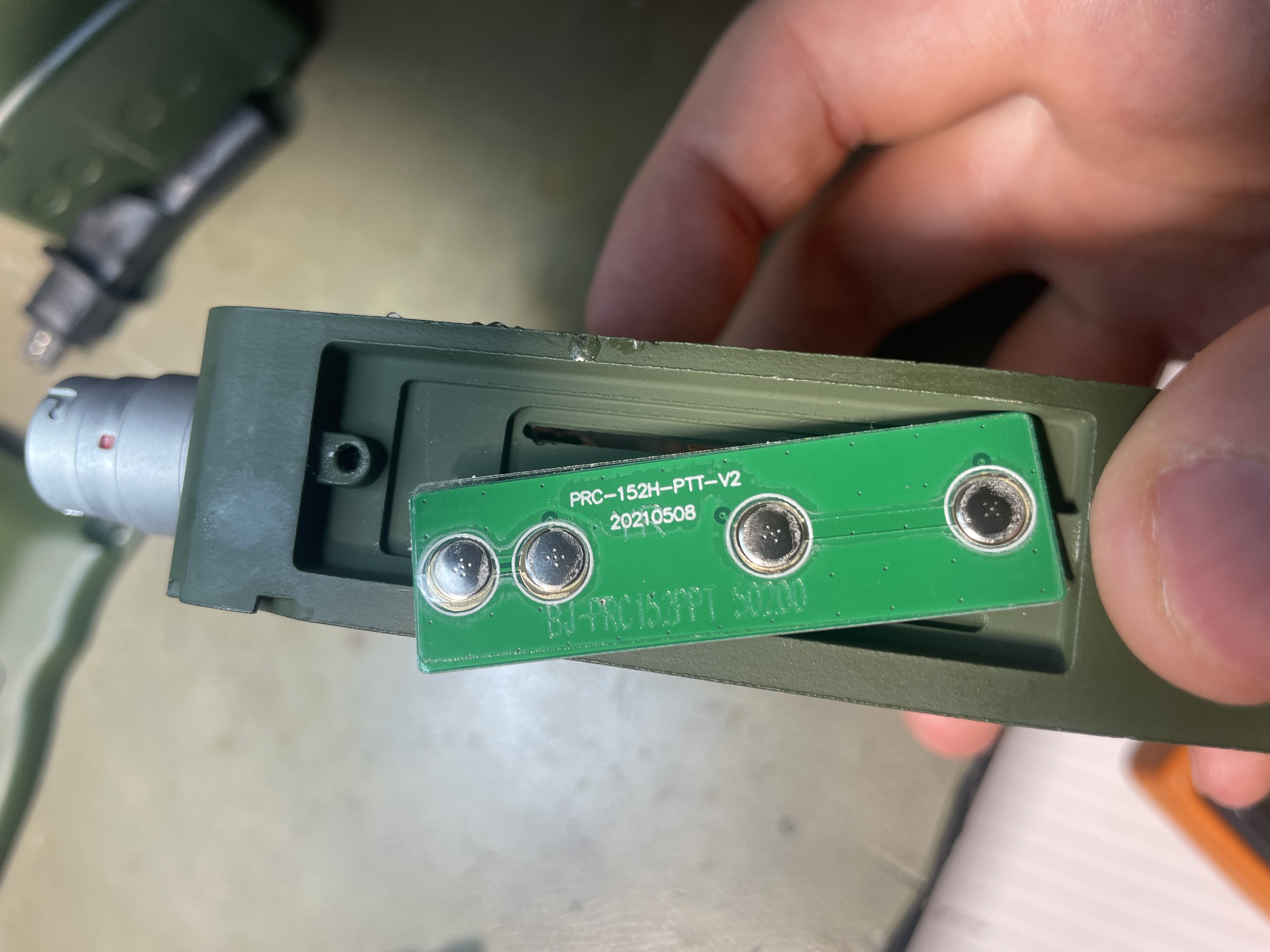
The side connector only breaks out a handful of the connections as seen in pictures above, the majority of the pads on the side are unconnected. It was also quite strongly glued in place.
The handset connector seems to be a genuine quality part, it has 5 V available to power external circuitry if needed.
The top knob has two decks, one is a volume control potentiometer (top) and the bottom deck has 3 positions selecting between different audio modes (bad, awful (companding), and spectral inversion scrambler). The bottom deck is a bit too lose in my opinion, and it is relatively easy to move accidentally.
Note that the original hardware clearly has a 9 position (36° increment) rotary switch for the top position, but from what I can tell there is no open-market combo switch that would work so they used a potentiometer with switch + coaxial encoder for the bottom deck.
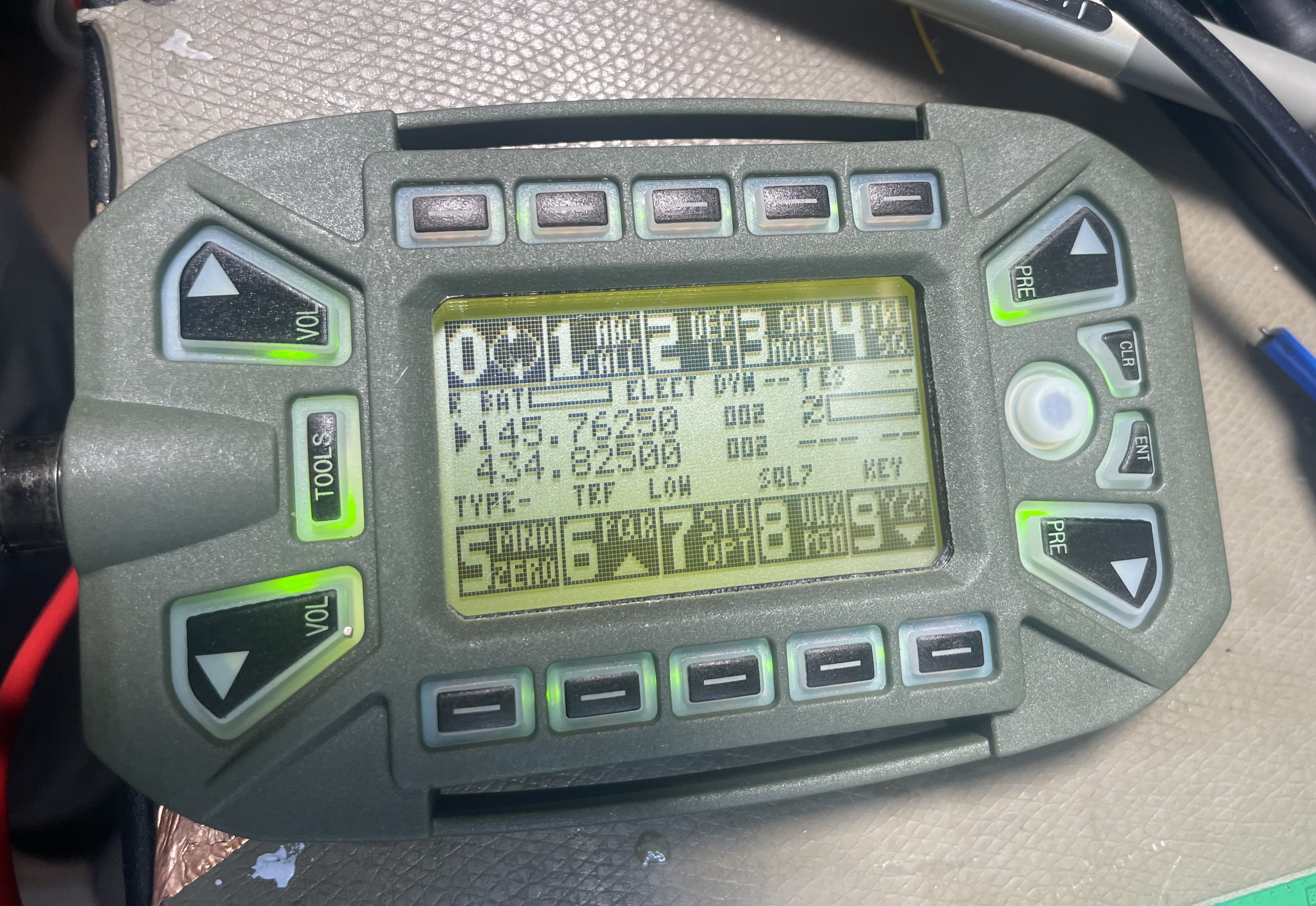
Curiously, there is an option to switch between potentiometer or digital volume, digital volume is adjusted with the top left side buttons like a real PRC-152. The KDU supports 20 volume levels, but I found both the analog and digital volume levels were far too high for indoor use (especially with such a poor speaker), and only the bottom 3 settings were usable.
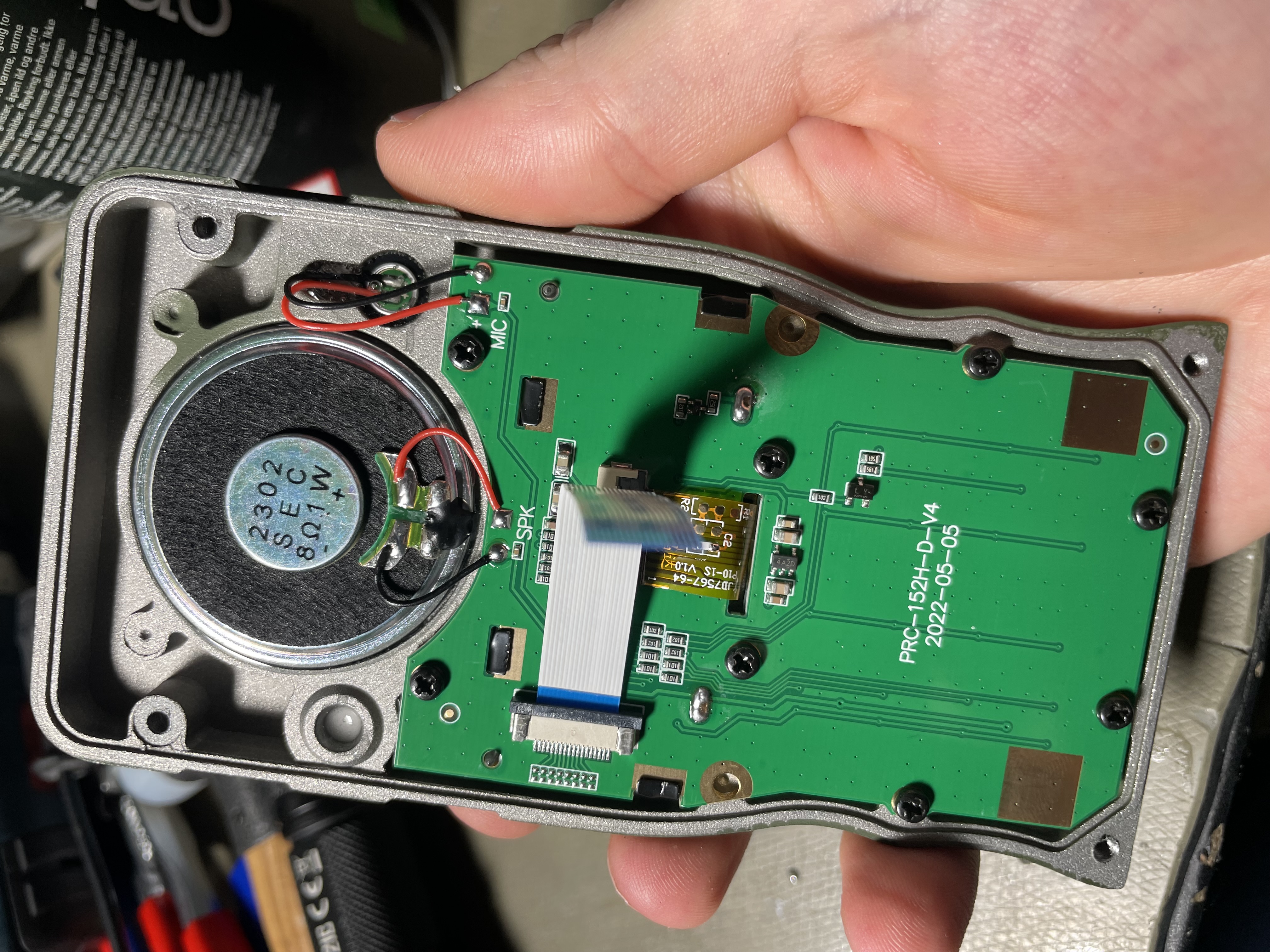
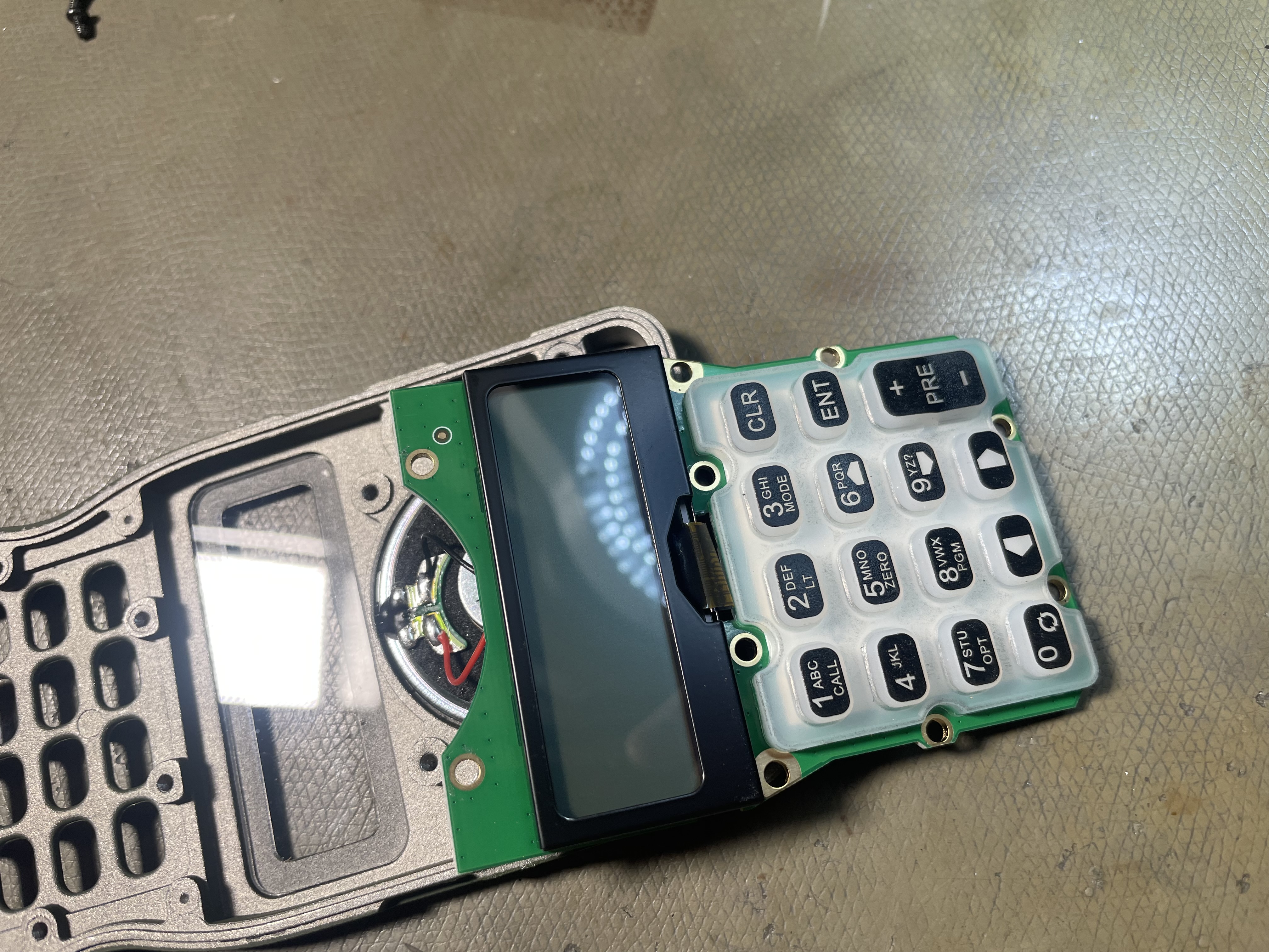
Front Panel
The front panel has a custom PCB which interfaces the LCD, speaker, and microphone, as well as the keypad. Note that for some reason the chassis includes positions for dual microphones but only one is installed (this may be intended as a pressure relief port though).
The keypad itself was adequate though not amazing.
The LCD controller appears to use an ST7567 controller or something very similar. The actual display is a pretty unusual 128⨉34 line. The two centre lines are also mapped to the end of the display memory, making bitmap-displaying pretty annoying.
Over all it's a pretty good display with decent viewing angles and contrast, and the pixel density is acceptable for a device of this type. The user interface implemented is not optimal though.
While the flex is marked YJD7567-64 this doesn't seem to turn up anything, but I believe the YBC12834 by Shenzen Ya Bin Electronics co. ltd. is a close match, and similar products can be found under various brands on sites like AliExpress.

Above is the dimensioned drawing of a module that appears to match the original LCD mechanically and electrically, but I have not purchased one to verify this. Just look for "12834 LCD" or similar.

The table above shows the pinout, which seems to be correct.
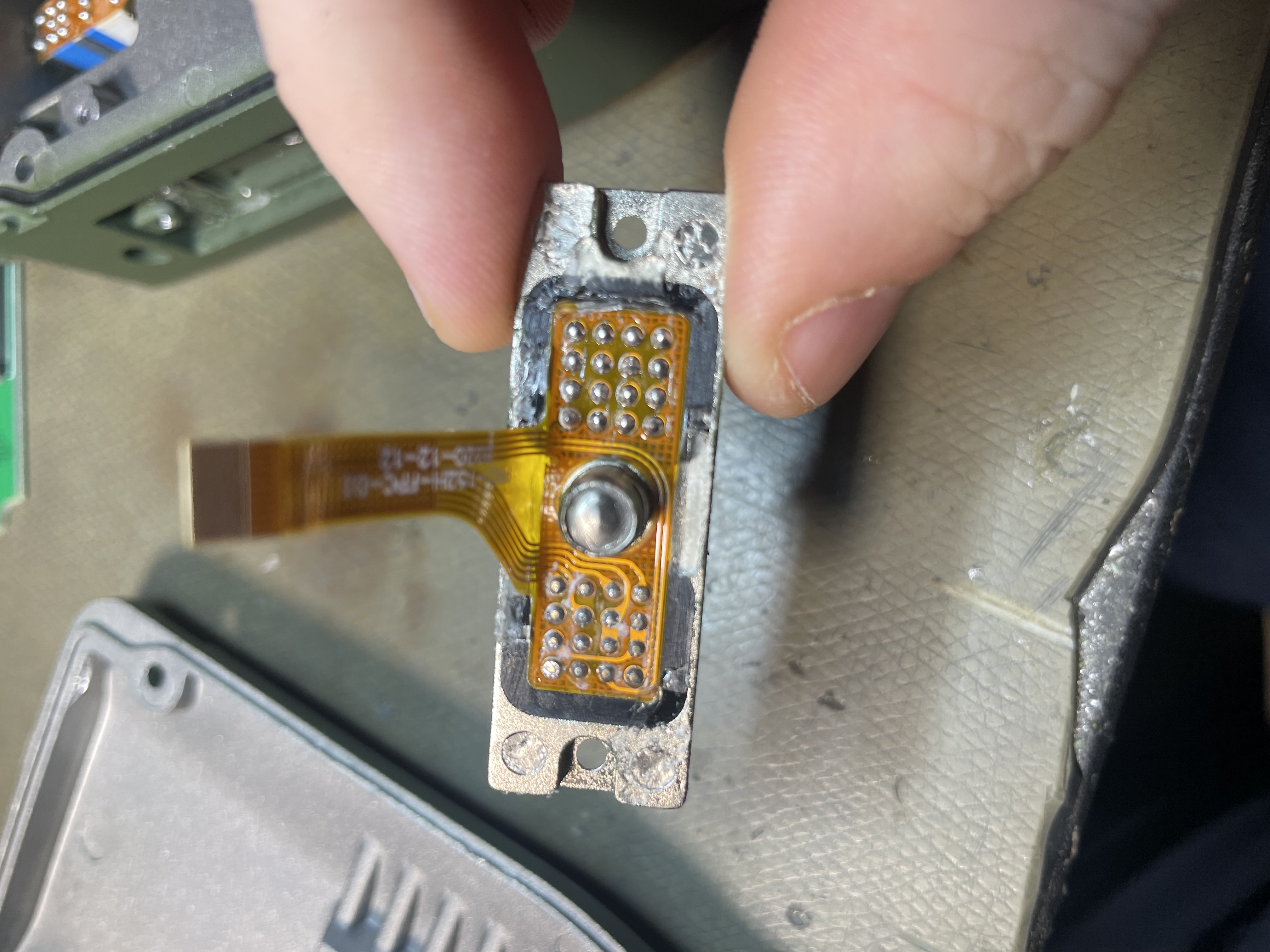
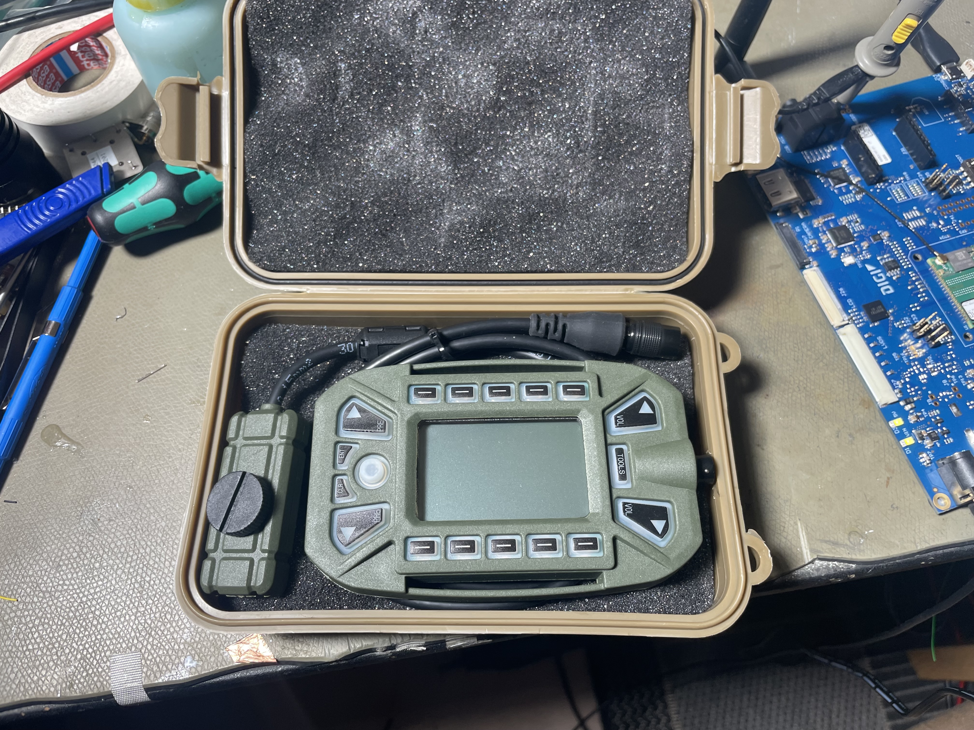
KDU
The KDU is a very nicely constructed device, it comes in a dedicated box as well!
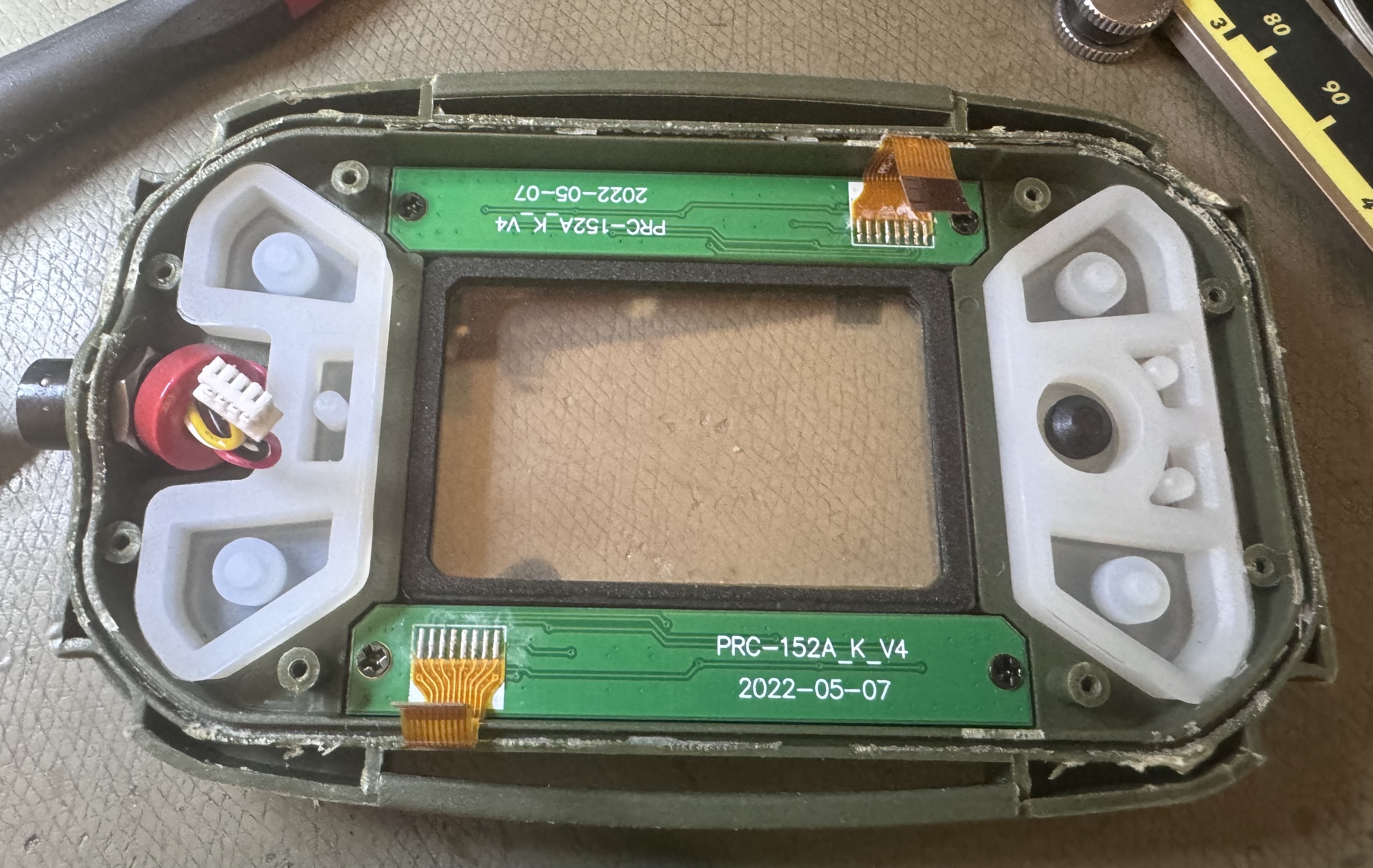
The device is fully glued together, and I didn't initially attempt disassembly. It appears to be more or less waterproof, and feels very solid. It uses a Hirose HR10 series 6 pin connector.
The KDU a serial device, the radio sends display state ever 50 ms or so in the form of a 32 byte burst, which is interpreted by a processor inside to drive the display. If the KDU is not refreshed every 100 ms or so it blanks the display.
This means there is no bitmap mode from what I can tell, and the display is largely limited to displaying the elements shown in the pictures. The top/bottom row indicators are generated by the KDU and mostly match what's printed on the radio button membrane.
It also transmits its' state every 10 ms, in the form of a 4 byte burst, this starts immediately upon power-on, even if no communications come from the radio.
The KDU is actually a pretty nice device on its own, and I've used it as an interface for a future project.
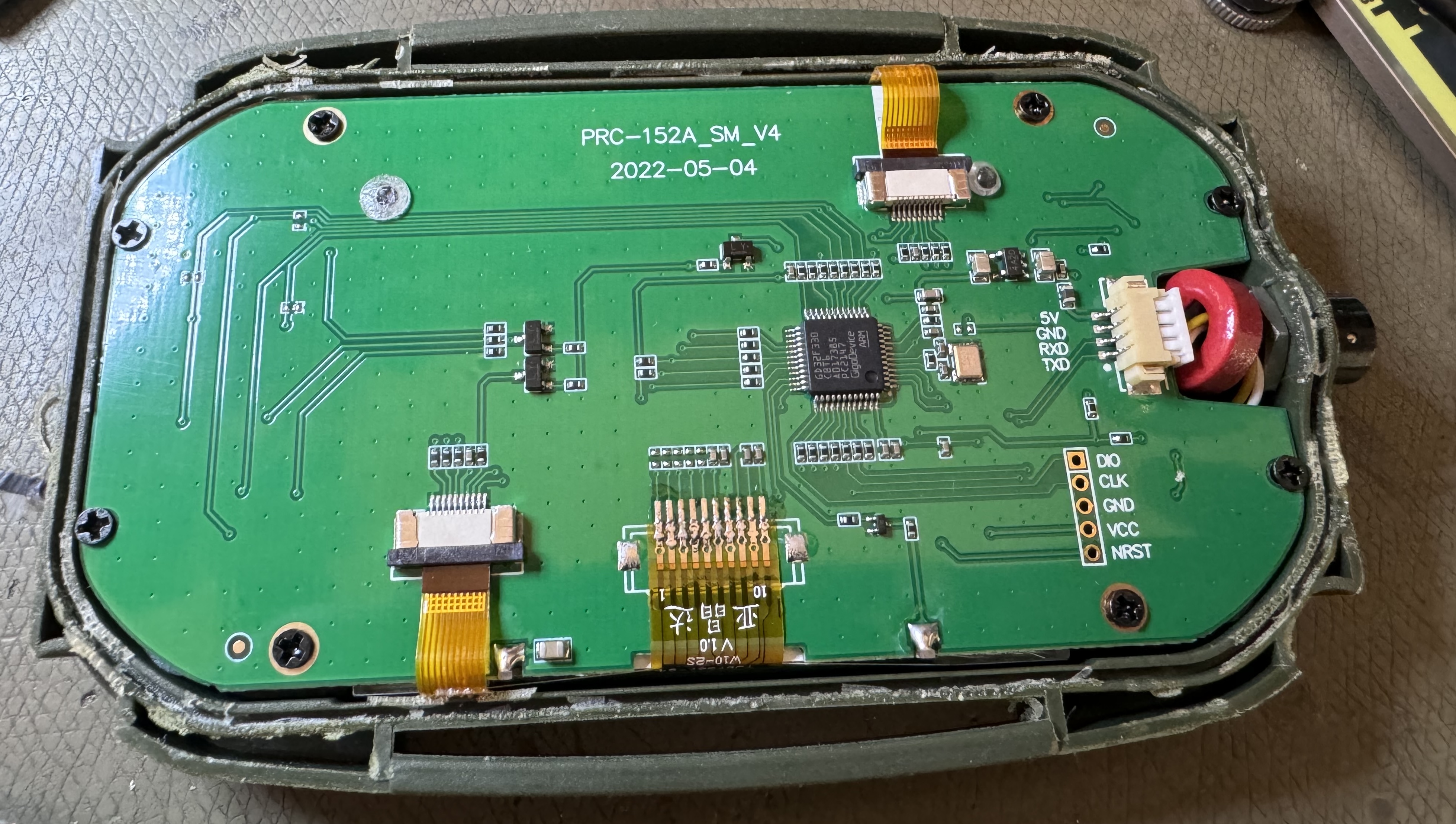
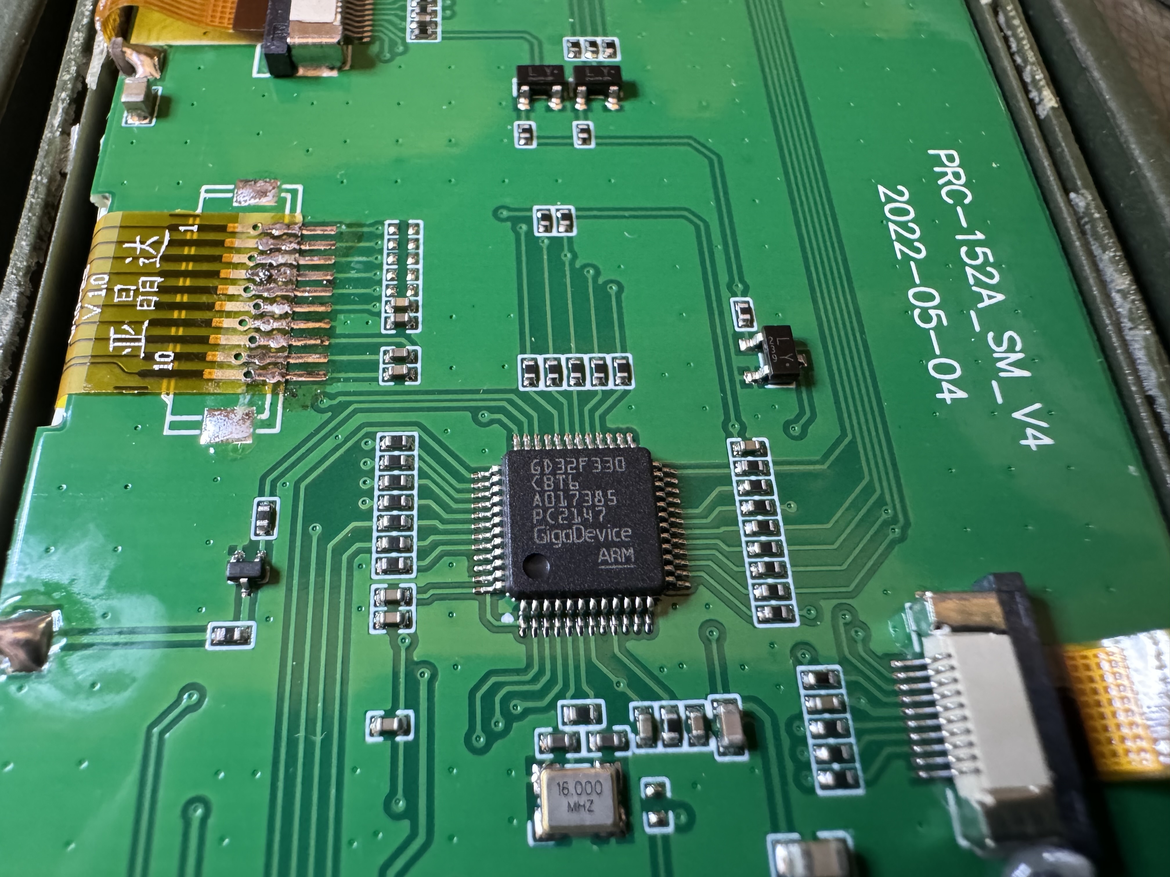
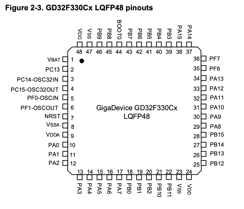
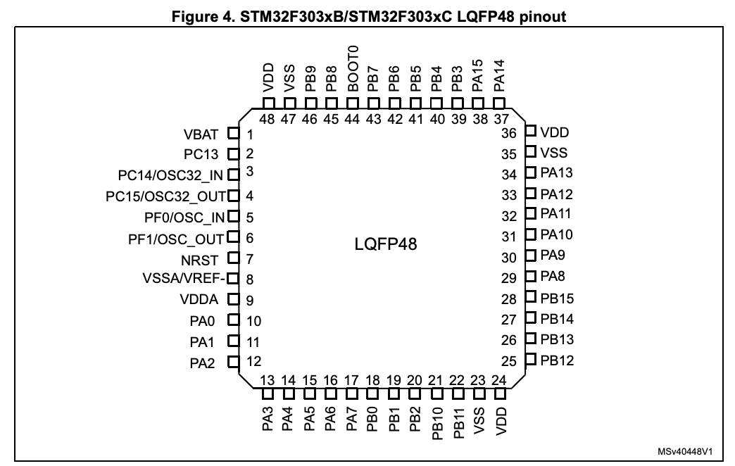
The main processor is a GD32F330C8, which is somewhat similar to a STM32F303 (but lacking the more advanced ADC's). This is a pretty powerful processor with an ARM-Cortex M4 processor core at up to 84 MHz. Below I clipped the GD32 and STM32F3 device pinouts, showing that they are almost pin compatible, except for pins 35 and 36.
There is an unpopulated SWD programming header on the PCB that could be used with a GD-Link programmer to reprogram this device if desired.
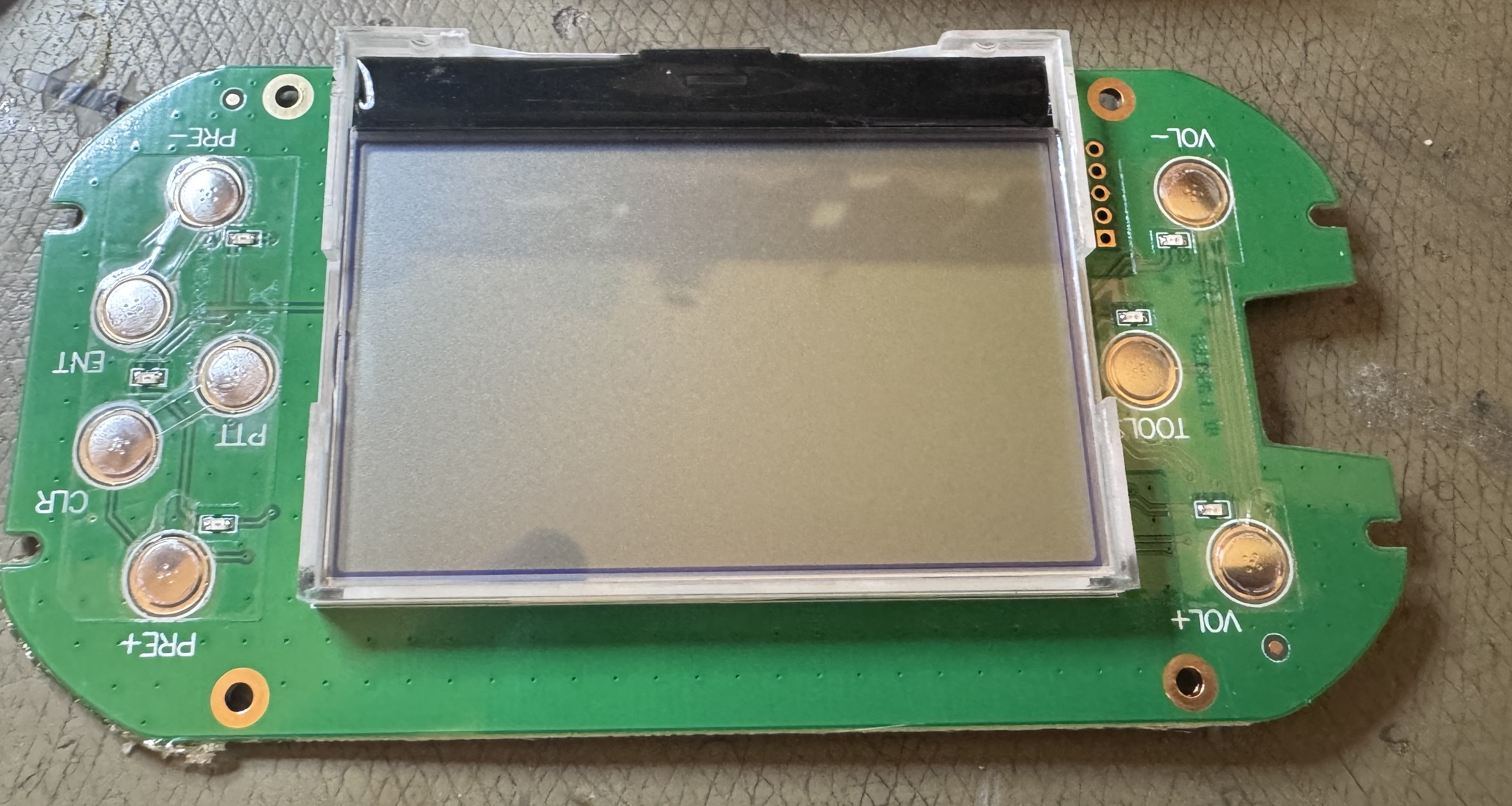
The LCD is heat-staked and soldered in place, but can be removed by sacrificing the heat stakes. The closest match for the LCD is a ERC12864-8, but some dimensions are slightly different.
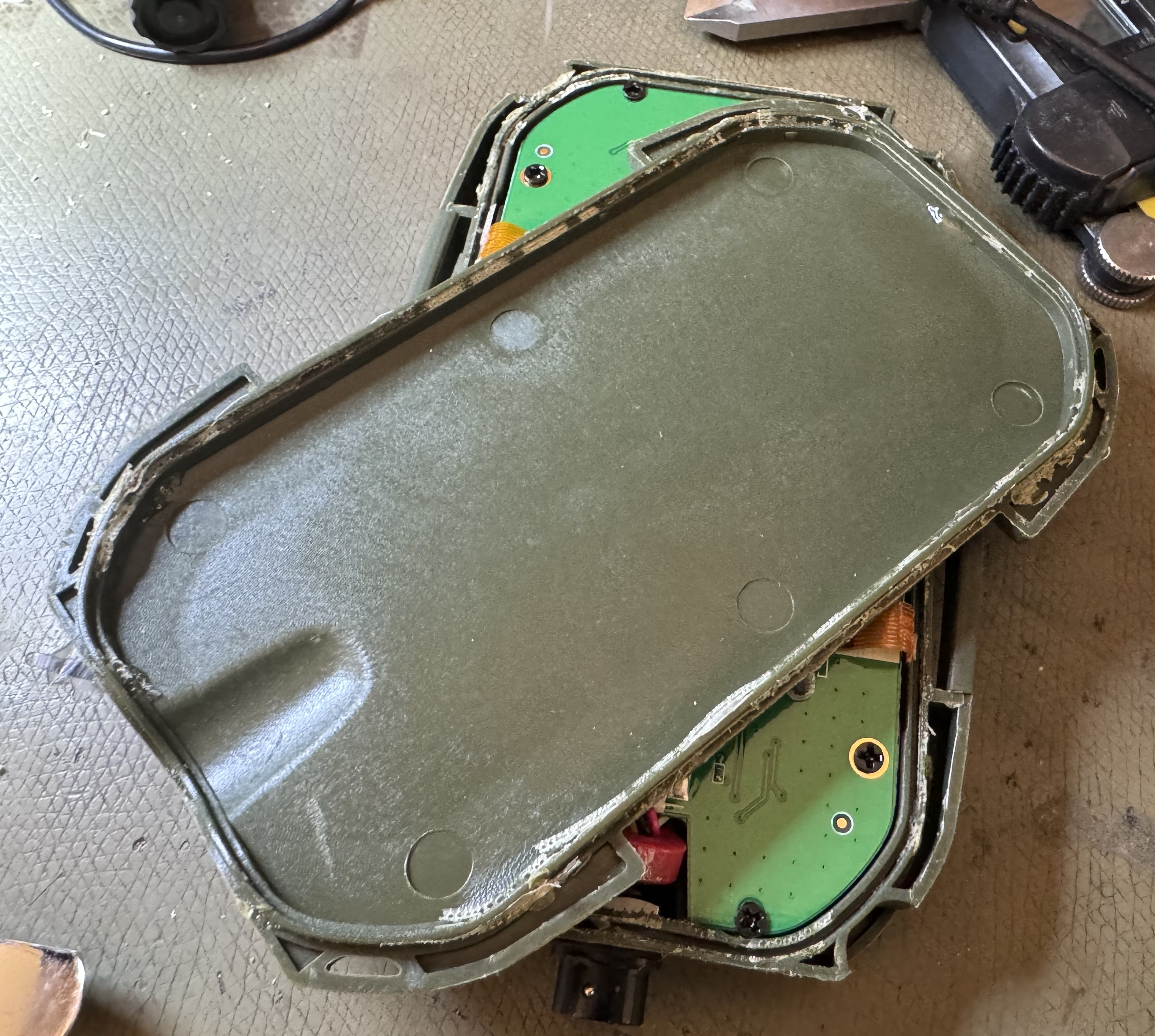
Case disassembly was slightly painful but using a metal spudger I was able to crack the glue at the corners and work my way through until it popped open.
Battery
The battery supplied seems to be around 60-70 Wh, and feels very solid. The charger PCB is just a straight adapter, only containing a single fuse (which is good).
I didn't measure idle power consumption, but the radio seems to have strong power saving modes typical of analog hand held radios (with no option to disable it). I would be surprised if the battery life was anything less than 48+ hours in standby.
This is basically excessive in my opinion, and they could have burned a bit more power instead to achieve more functionality.
RF Performance
I didn't bother testing it beyond the basics, it's a modern single-chip radio, and performs as such. Sensitivity is excellent as usual, but audio quality is lacking.
The RF power seemed to be in spec for the standard 144/433 bands.
Summary
It bears repeating; the chassis and build quality is excellent, all the right gaskets are in place, custom flex PCB's with gold plating are used even where cheaper options would have worked.
A significant number of gluing operations have been done to ensure watertightness. The side connector seems to be made from custom machined metal pieces and plastic casting jigs. The chassis is cast and machined aluminium. The battery spring terminals have their own PCB with a custom silicone moulded plug-seal.
All the buttons are snap-domes which seem to be assembled in a jig and retained with a clear polyester tape that covers the PCB (fairly standard high-volume technique).
It seems like several custom hardware pieces were made for this device even though they could have easily skimped out.
Unfortunately the audio and UI issues were a bit too much for me to actually use this radio.
Future Work
I have deemed the chassis to be worthwhile, and my current long term plan is to design a new SDR transceiver to fit inside the rather spacious internal volume.
At initial issue of this article (July 2023) I've gotten to the point of driving the external KDU with custom software demodulators (using two RTL-SDR's as receivers, currently capable of FM/AM/SSB). Some chassis pieces have also been modified.
This system will definitely burn significantly more power, but one benefit of a large chassis is the accompanying large battery.
Additionally, I've made a new front panel PCB with a better speaker and dual microphones, though the work of driving the original LCD (it's an unusual LCD…) with a new processor has not started yet.
Chassis Upgrades
Note: the new front panel PCB is in no way compatible with the original radio hardware, though it would be possible to e.g. replace the speaker with the OWS-4065T-4C 4 Ω 3 W speaker I used here without any major issues.
This waterproof speaker works fairly well in this enclosure only requiring a 1st order 400 Hz high pass filter to eliminate some boomyness.
I also selected CMC-2742WBL-25L IP57 microphones for this project. This microphone doesn't fit the holes as such, requiring some minor reaming on one side and a bushing on the other. They also require a 1st order high-shelf filter to boost the treble to acceptable levels.

I decided to put in a front facing bi-colour LED, and added top/front light-sensors to auto-dim the backlights.
The top knob can be replaced with a MA00S1NCGF 10 position rotary switch with only a minor reaming operation and fits the top knob both in shaft distance and angular increments. Two pins can be installed in this switch to limit the rotational range to the 9 assigned positions.
Above the mentioned rotary switch is installed and aligned, a new FFC PCB has been ordered for this purpose. Also visible are new custom FFC PCB's to break out all the side-connector pads (though a few are dedicated to ground and commoned).
As part of this effort, I had reason to work out the exact make and model of the original LCD to be able to drive it properly.
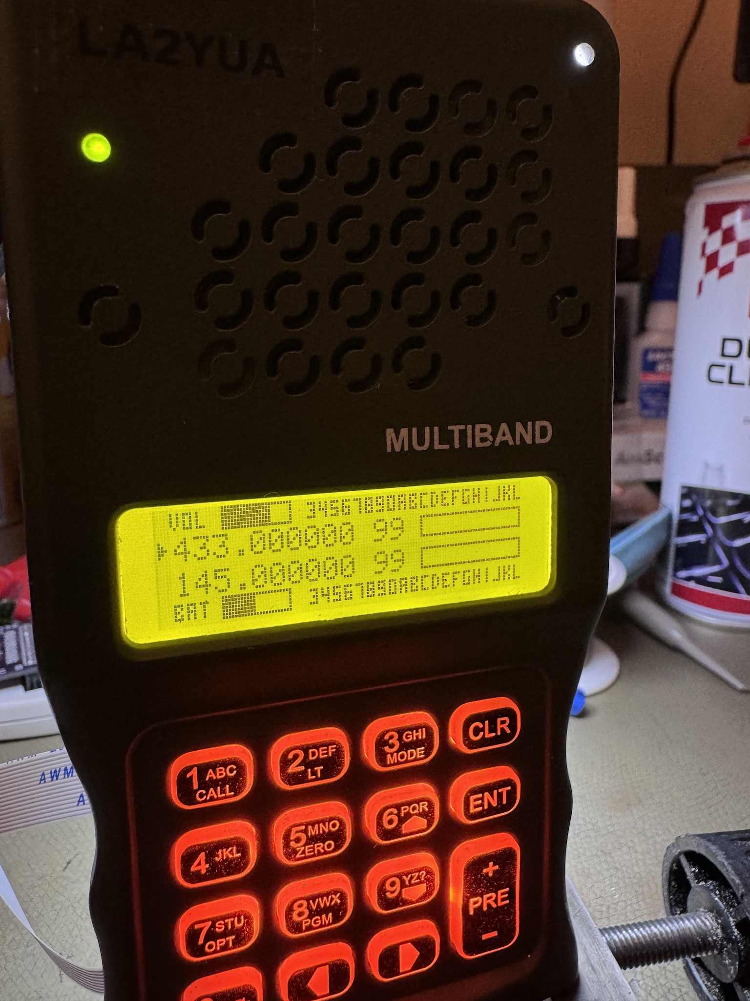
Above a work in progress from April 2024 shows the new front panel with functioning keyboard, backlight, and LCD drive. Additionally, a red/green front panel indictor was installed, and a set of light sensors is used to control the brightness of all indicators.
Addendum: Reliable AM Squelch & FM Threshold Extension
During my recent work on implementing my own SDR transceiver (at present only a receiver though), I implemented FM reception and noise squelch using fairly standard principles.
The basic concept of noise squelch for FM reception is to detect the signal to noise ratio of the received signal, for FM this can be done by tapping the discriminator, passing it through a band-pass filter centered higher than the audio cutoff (e.g. 5-10 kHz), and rectifying this.
With decreasing SNR, a combination of gaussian noise and impulse noise increases significantly near the quieting threshold (typically around 8-10 dB RF SNR). This increase in noise occurs at higher frequencies first (in particular, the impulse noise generates high order harmonics). By sensing high frequency noise, a reliable SNR estimator can be made, and the squelch simply checks the level of the noise detector to determine if a signal of sufficient quality is present. For more information look up FM thresholds effects, and also this NASA paper: A study of FM threshold extension techniques
Note that since higher frequencies degrade first, CTCSS reception is generally possible at extremely poor signal levels, which is why CTCSS detectors are always paired with a noise squelch system. Use a Goertzel tone detector for CTCSS by the way, I implemented a single detector and found performance was excellent, though it needs noise squelch to work well (since it only measures power in a band, it will trigger on noise as well).
Note also that the noise squelch detector signal can be used as a gain-control signal for the receiver audio to implement a basic noise reduction/soft-squelch system in combination with a noise-gate signal from an audio level detector. When correctly tuned, a few dB of extra sensitivity can be achieved for typical speech.
In any case, I started with FM reception and then later implemented AM reception (which is far simpler, and actually a side-product of my FM demodulator). I was initially surprised I had a functioning squelch, given that I hadn't implemented AM squelch yet. The FM noise squelch system was instead active, and this actually worked!
My observations indicate: running a full FM receiver with noise squelch in parallel with the AM demodulator works, though is a bit resource intensive. The reason this works is since the FM receiver is more or less able to lock on to the AM carrier and detect this (also possible is AFC, using this system).
The SNR to noise-detection function is more linear with AM signals (it's quite non-linear with FM), requiring different thresholds and narrower hysteresis to work well.
Testing thus far indicates that this squelch method works quite well in my area, and the noise-rejection ability is more or less equivalent to an FM receiver (i.e. significantly better than what actual airplanes have).
I suspect this squelch method may have some caveats in certain RF environments with e.g. adjacent channel signals, though I haven't tested it yet. In my area this does not seem to cause issues.