Devlog 2 — The Falcon II KDU

Following the previous entry, the PCB's for the early summer 2024 assemblies have arrived. First out is the Falcon II KDU PCB's, which replace the original PCB while reusing some of the key components.
Table of Contents
Design Goals
The purpose of this design was to make a form-fit-function replacement of the KDU internals. As mentioned previously the KDU used early 2000's design and with absolutely no software interface documentation it was not feasible to reverse engineer the existing design.
Additionally since I am also making the PRC-152 front panel, and the 152 KDU replacement, I want to standardise software interfaces with more flexibility than e.g. the original 152 KDU offered.
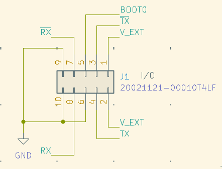
I'm also trying to make all devices in the system remotely programmable over serial – as such I made the original "KDU Detect" line in the 7-pin connector connect instead to the STM32 BOOT0 pin. This pin can be set high before powering on the device to enter serial bootloader mode. This change may actually make this incompatible with the original PRC-150 radio, but it's not like I have one of those.
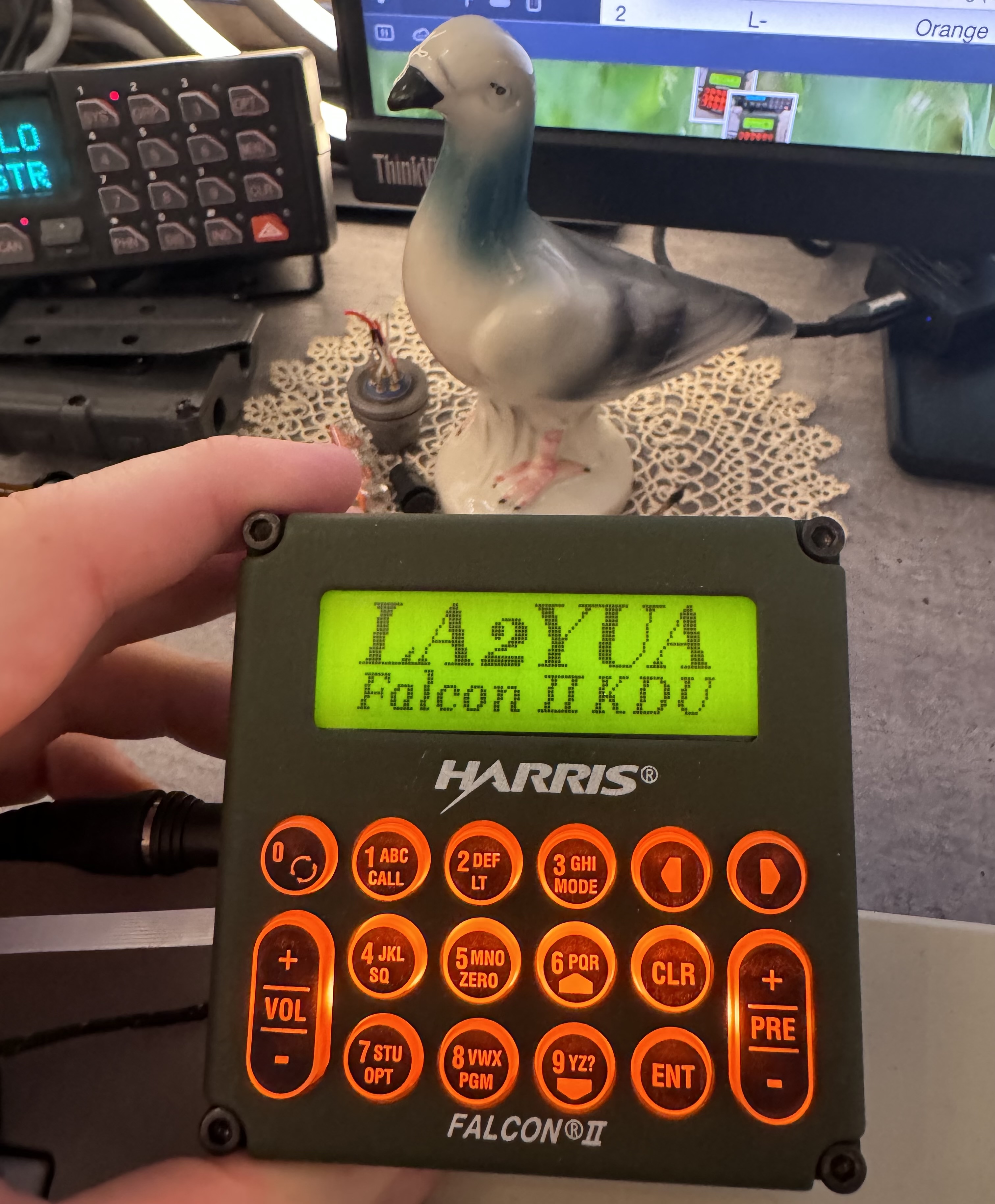
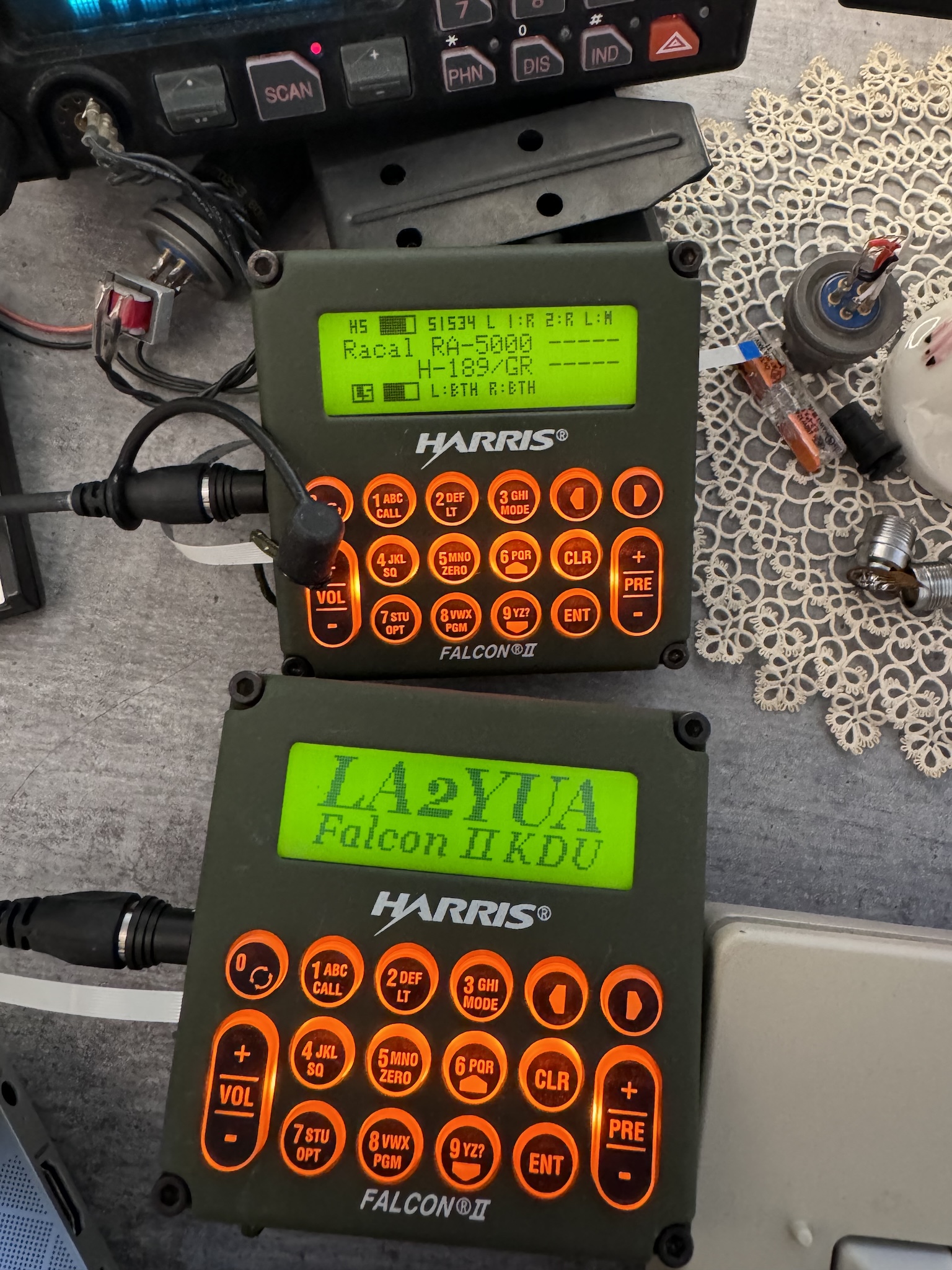
Above the new bootsplash image is rendered. This image is shown for a second or two on power-on, and whenever serial communications stop for more than approximately 1 second.
PCB's
The circuit boards are relatively simple, but with some relatively complex geometry.
A 4-layer board was used as usual, and I chose to use ENIG and epoxy filled/capped vias to use via-in-pad. This saves some space, but is not a critical requirement.
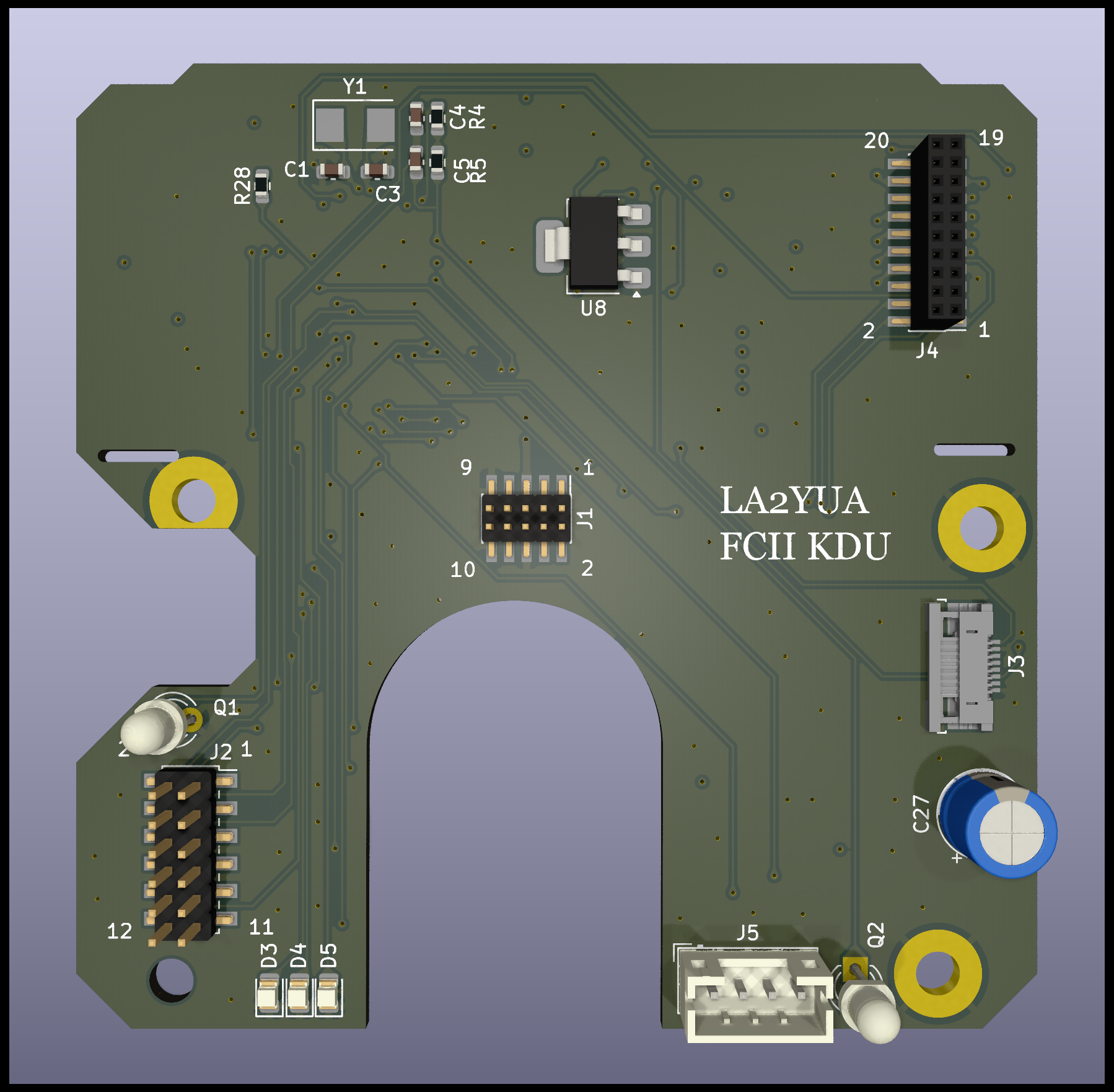
Above a front 3D render is shown, where I basically have nothing. The LCD is not modelled, but slots are present to use the original mounts. The pin header connectors simply reflowed off the old board and soldered onto the new one.
Q1/Q2 are phototransistors, which are not currently used but by drilling some holes in the case these could be used as light sensors.
A JST PH connector was used for the two LCD heaters, the original connector was slightly more compact but the new design had plenty of room and this was cheaper.
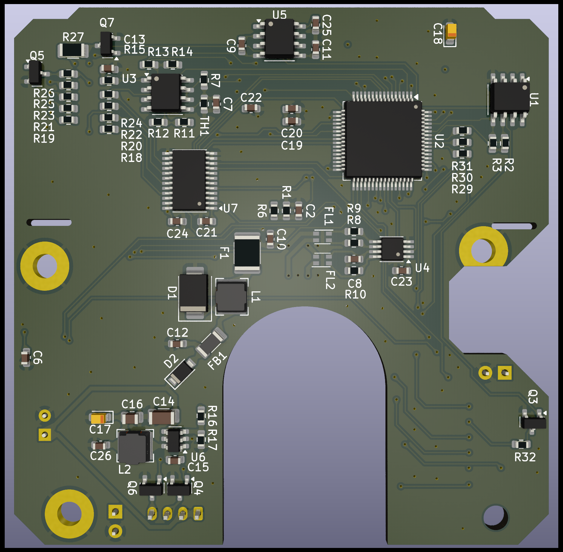
On the back we have some stuff. The main processor is an old standby, the STM32F103RE. This is a processor with a reasonably large 64 kB RAM and 512 kB of flash, in a 64 pin package. It's a good choice where a relatively large amount of I/O is needed. An F-RAM IC is used as usual to store configuration parameters such as the LCD contrast.
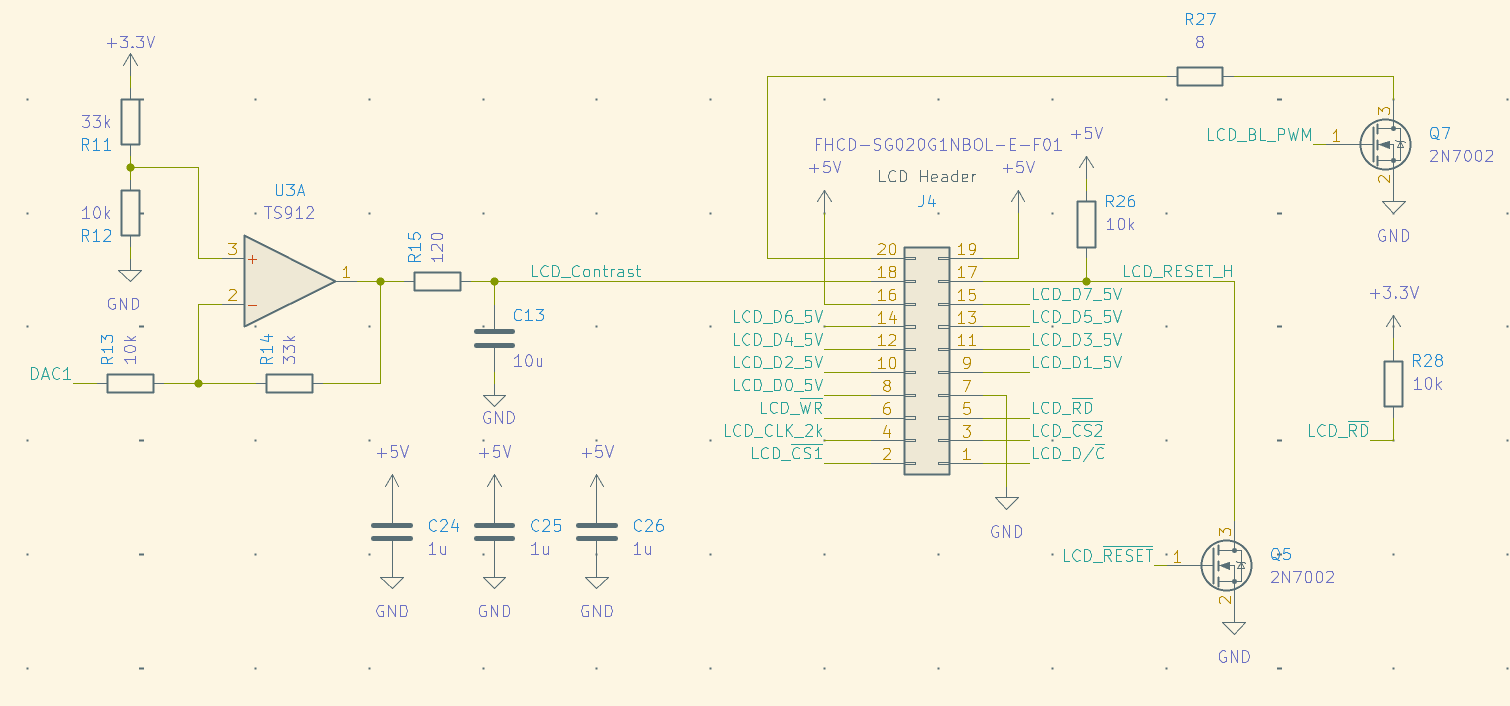
The LCD interfacing added some complexity since the data lines run at 5 V, while the control lines can be 3.3 V. A 74LVC245 level shifting bus transceiver was used. I found that the 2 kHz LCD clock can be overclocked but it doesn't seem to affect anything, at excessive rates the LCD visual quality is affected somewhat.
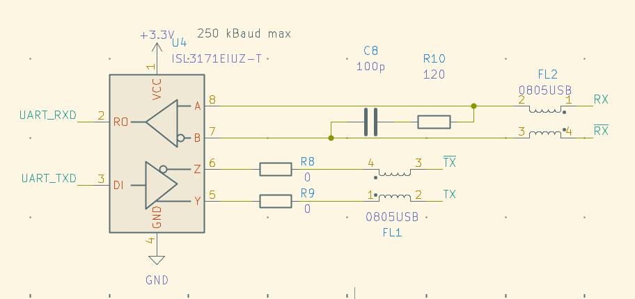
For interfacing, a slew rate limited RS-422 transceiver is used, and a TI TPS560430XF DC/DC controller was used to support a wide ~7-28 V input voltage range.
To bias the LCD an opamp and an ICL7660 was needed to generate up to -5 V. I used one of the MCU's DAC outputs to drive this, giving ample resolution.
I opted to modify the button board by replacing the original green (0805) LED's with more modern and æsthetic orange LED's. This increased efficiency was a mixed bag, since I couldn't easily replace the LCD backlight.
This backlight is very dim, requiring a very high ~100 mA operating current to reach approximately 1⁄8th of the intensity of the orange LED's. Naturally, all the LED's are PWMed so I was able to adjust the intensity to be reasonably well matched.
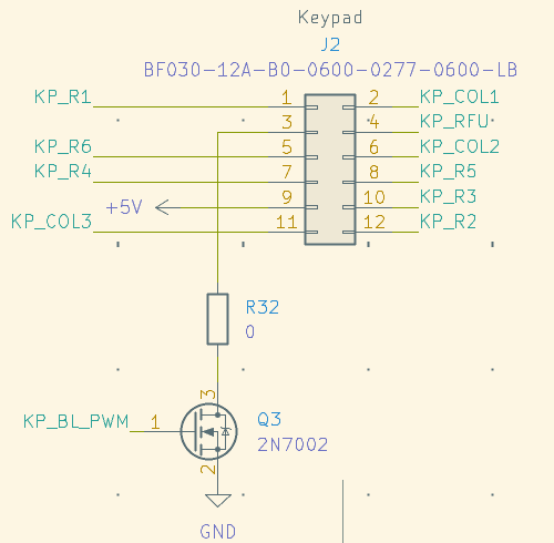
The pinouts for the other connectors are shown below, but note that I had to make special mirrored footprints to make these line up with the original pinout markings. Ignore the part numbers, I hot-aired the plugs off the old board and used those to save mone—to ensure perfect compatibility with the LCD and front panel.
Software
The MCU software is written in the STM32 IDE, where I opted to use FreeRTOS as a dispatcher, similar to the RF-5980 design.
LCD
The LCD interfacing was surprisingly simple, and getting an image on the screen only took an hour or two. The parallel 8080 interface is not particularly difficult to generate using GPIO, and I saved myself some grief by ensuring that the 8 data bytes were placed in sequence on a single GPIO bank. This way I can easily use the BSRR registers to flash out my data byte.
I also implemented BUSY signal readback, but this is not generally needed in my experience. I was only able to exceed the LCD controller's speed once I switched to -Ofast optimisation. A few strategic 1 µs delay calls ensure appropriate delays even in this case, and reaching ~100 Hz update rates was not difficult.
Most of the hard-ish work of getting a graphics library working was already done for the TRI PRC-152 front panel shown in the previous log entry. As such all I had to do was clean up the code a bit and modify it to use a 122⨉32 display instead of the (even weirder) 128⨉34 display of the front panel (and the less weird 128⨉64 display of the TRI KDU).
This difference amounts to one less 5⨉7 character of text on screen, which shouldn't be too difficult to deal with later when I will want to use the same code to talk to both devices.
Comms
The serial communications use DMA as expected, running at the maximum 230'400 baud (with 250 kbaud⁄s limited transceivers). A simple framing format used for the speaker is repeated — a message starts with a ':' and ends with a carriage return, a newline can be used but is ignored by the parsers. I also use a pipe character ('|') to separate the header from the payload, making manual decoding of the data easier.
All data is encoded as a hexadecimal string, meaning a 2x overhead is incurred, with the benefit being highly reliable framing, and the communications are printable making debugging easier.
A separate FreeRTOS task polls the DMA transfer and processes data, along with scanning the keypad and generating messages periodically and when keys are pressed.
Some header information indicates source/destination and message type, length, and a CRC-32.
This header is common for all messages in the system, and ensures that a message router can receive, verify, and pass along an unknown message. E.g. the RF-5980 speaker controller does not have the headers and code to parse and inspect the contents of KDU messages. Instead, it only needs to know the routing information (what UARTs the packets will go to/from, and their source/target id's).
Interface
The KDU accepts a structure defining the display state. The default display has a 2-line 5⨉7 center text field and top/bottom 4⨉6 text fields. Small bar graphs on the top/bottom are controlled numerically and can be turned on/off, and larger bar graphs on the center lines intended for volume/RF level display are also parametrised.
It's also possible to switch to all-text in large or small text, making a character-mode display suitable for making e.g. menus.
The keypad is scanned and debounced continuously. When a key down event is detected, an output field containing an ASCII representation of the button is output once per press. This makes it easy to implement getc() type serial processing of button presses.
Additionally a bitfield is output representing all currently pressed keys, and various runtime parameters like backlight state, LCD bias levels, serial number, reset-cause, on-time, and a sequential message counter.
The output data is generated twice per second, and whenever a key-down occurs. This ensures that the device will respond quickly to keypresses without overwhelming the speaker-radio serial bus with excessive data. The timer based transmission is useful to ensure that the KDU is always signalling its presence to the upstream controller.
Testing suggests that any 4 keys can be detected properly, when a 5th button is pressed depending on combination some ghost keys are detected. This is sufficient to implement e.g. a shift-key type overlay.
Test Integration
As part of the larger system, the RF-5980 speaker connects to the KDU and acts as a message router. Messages are then passed between the KDU and the Pi Pico based interface test board, and then passed along to a PC control software for monitoring.
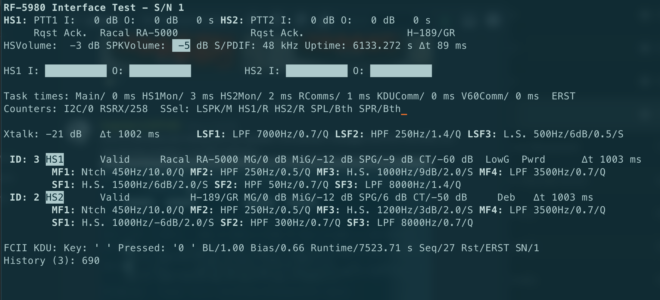
Above a screenshot of the console mode monitoring application is shown. This program is really just an interface test, and has been very useful in developing and debugging the system. In the current state, the program talks over USB-serial with the Pi Pico.
When running on Linux it can also be connected directly to the RF-5980 speaker — the restriction is mainly caused by the macOS USB-serial drivers not supporting baud rates above 460'800 while Linux ones do.
Lacking an actual radio as part of the system, the KDU currently controls some parameters of the RF-5980 speaker system. This is done by parsing the RF-5980 telemetry in the Pico board and generating display data for the KDU (e.g. handset type selected, on-time, audio routing, volume levels etc.).
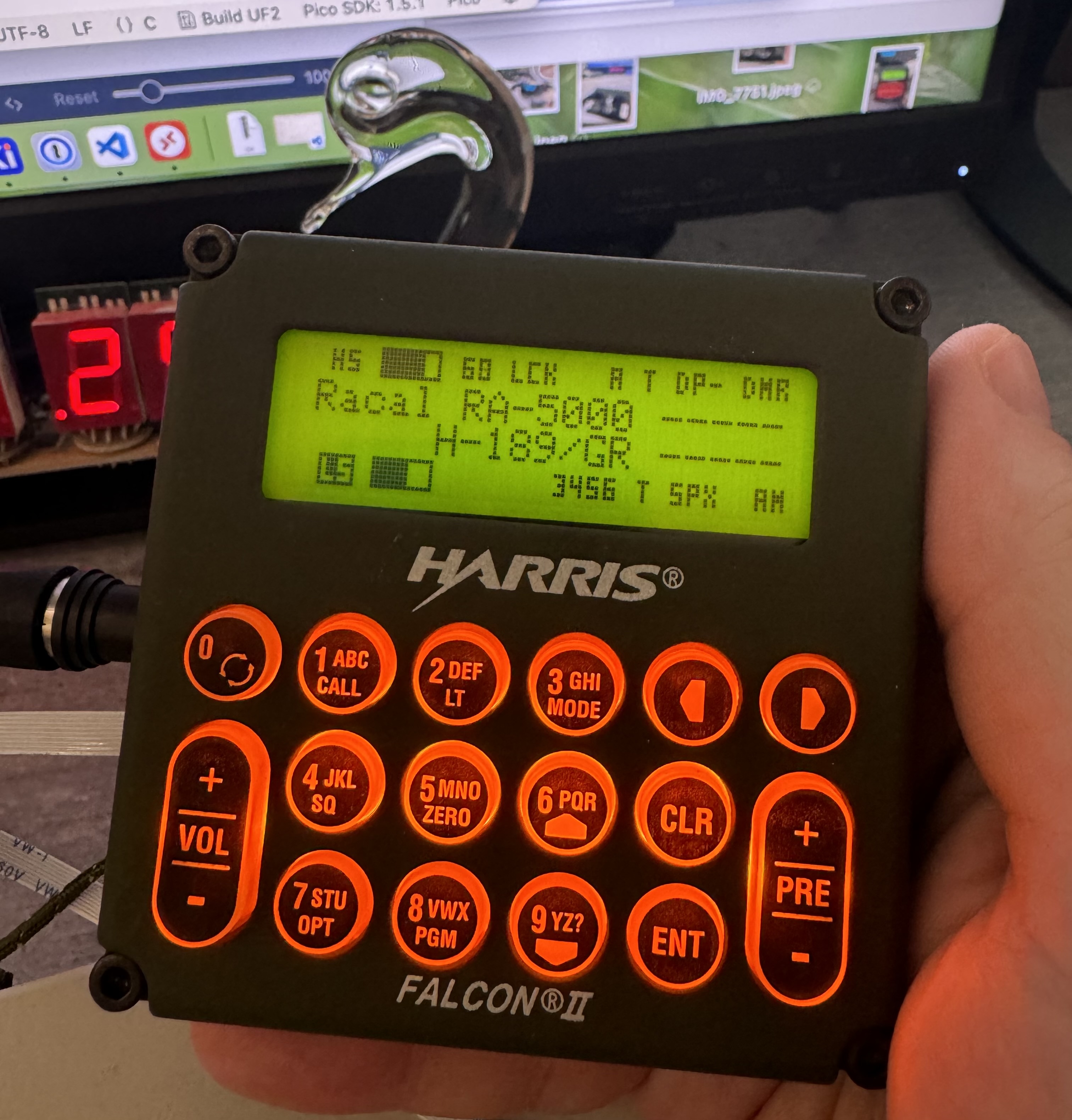
Above the KDU is presenting parts of the RF-5980's state. Top row shows HS state (muted), volume (~–3 dB), on-time of the RF-5980 speaker (60 seconds), and S/PDIF lock state. The center rows show the names of HS1 and HS2 profiles, and the dashed lines switch to VU-meters when PTT'd. The bottom row shows the loudspeaker is unmuted at around –5 dB volume.
The KDU response is parsed in the Pico and controls parameters such as handset type.
Notable Issues
The major issues found during initial assembly and testing included:
- Swapped Anode/Cathode on the LCD backlight – modified the LCD
- The newer LCD modules used by most of the KDU's I have include solder-bridge pads to make this easier
- Swapped +/– on the RS-422 transmit lined — fixed by mod-wires
- Excessively dim LCD backlight – fixed by reducing series resistance from 24 to 8 Ω
- This is using a large part of the 600 mA 5 V bus current budget. I should also swap the 2N7002 for something with low on-resistance since this is probably significant now.
- Partial disassembly of the LCD module suggests that LED replacement is not trivial
- Surprisingly high LCD bias currents – originally I had 10 kΩ in series but I ended up using 120 Ω instead.
- RF-5980 S/N 1 had a defective RS-422 receiver
- A 0805USB common-mode choke had an open pair.
- This still allowed data transmissions with a high bit error rate, preventing successful decoding.
- Fixed by swapping the choke. These devices are pretty fragile and harder to hand solder reliably than most other SMD devices.
- Software bug introduced in the Pico interface board had me chasing spurious button-presses for ages
- Turns out the Pico would sometimes forward KDU keypress packets twice.
- Fixed by using the sequence counter field to handle this case. I also fixed the logic bug in the Pico code, of course.
Conclusions
Over all this project has been successful.
The issues identified during assembly and testing were not unreasonable. The mechanical aspect worked out perfectly, electrical interfacing was a success and the mods were not excessive.
Software-wise no major issues were found really. An attempt to use FreeRTOS queues to pass messages along seemed to have some issues with latency, though I suspect they were overloaded due to a bug elsewhere that caused excessive traffic.
The addition of relatively high speed message passing for the KDU does not seem to have significantly affected the workload of the speaker processor.
At the time of publication I have assembled 3 units, with the only adjustment needed being the contrast voltage. Sadly, the first unit I tested seems to have a better LCD panel than the remaining units, which show somewhat reduced contrast.