Devlog 1 — PRC-152 Knockoff

The original Tri PRC-152 I purchased in 2023 was not a very good radio, with the biggest issue being a very limited radio with very poor audio.
This is a summary of the current work up to summer 2024, with future entries to be added as I go. Realistically this won't be a finished design before mid 2025.
Table of Contents
Replacing the Front Panel (Finished)
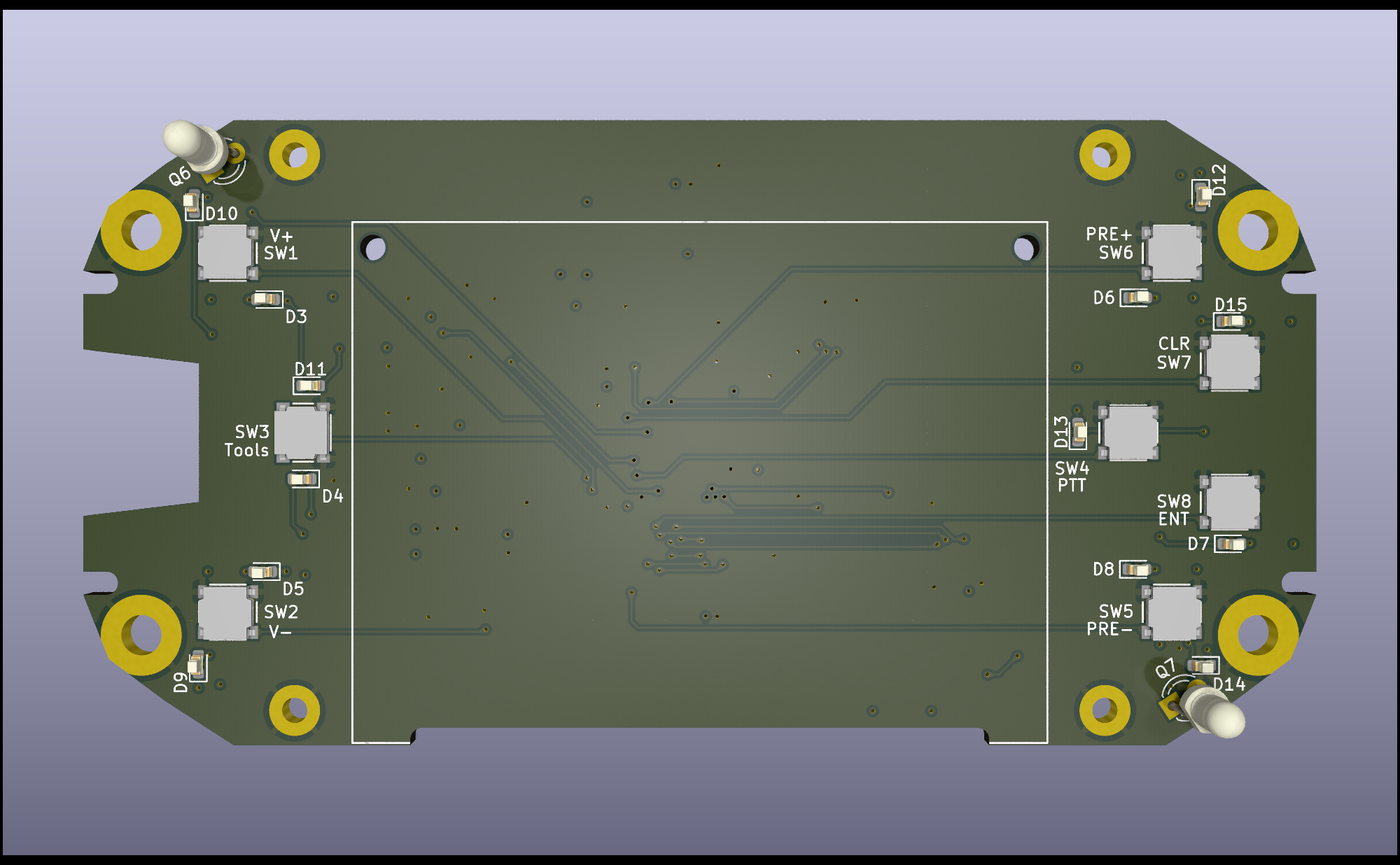
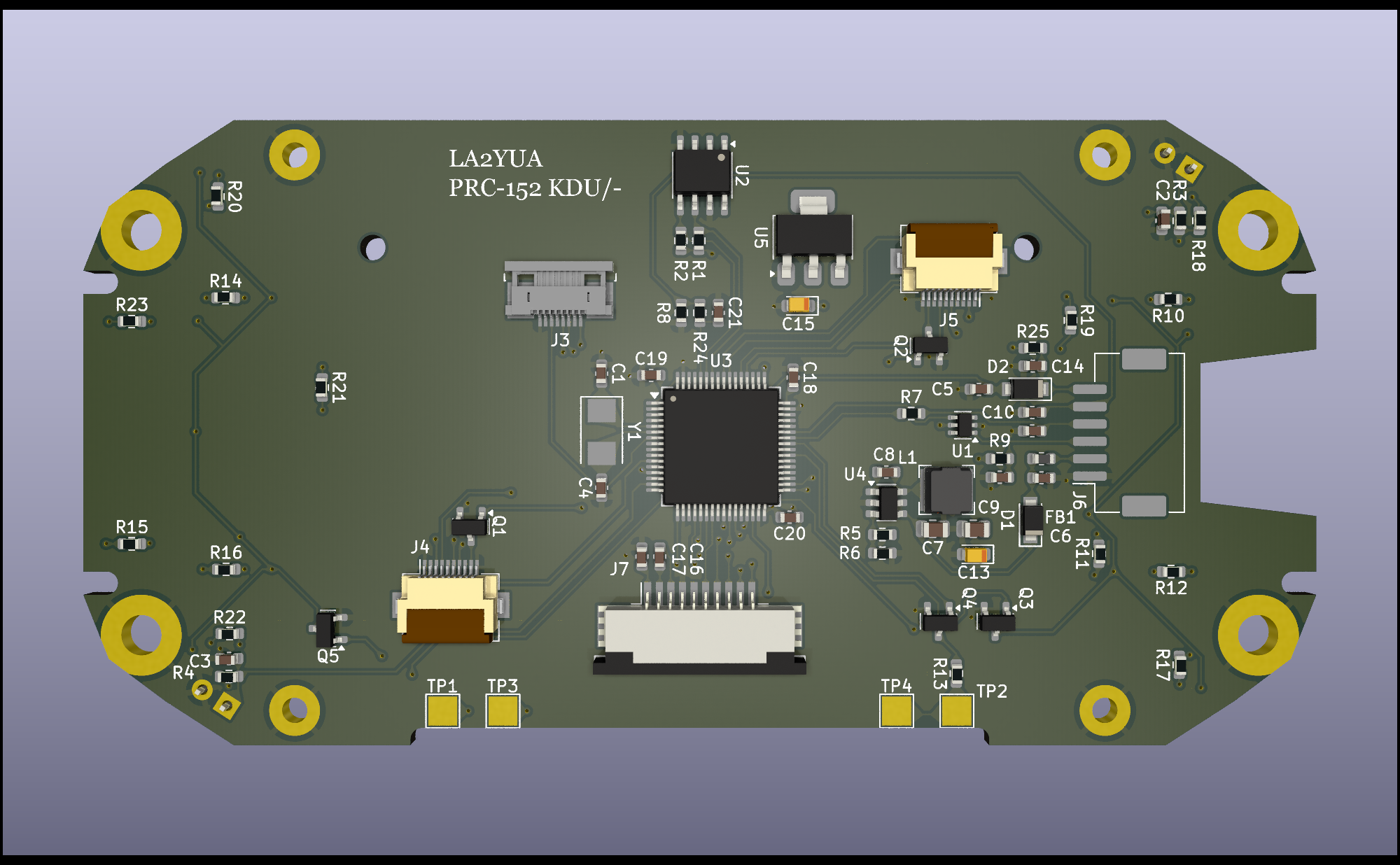
The first board I made was the front panel replacement, a mostly standalone assembly. I elected to add a local micro-controller to the front panel to handle button readout and LCD control. Additionally, I moved the speaker power amplifier and microphone pre-amplifiers to this board, and I expanded the number of microphones from 1 to 2.
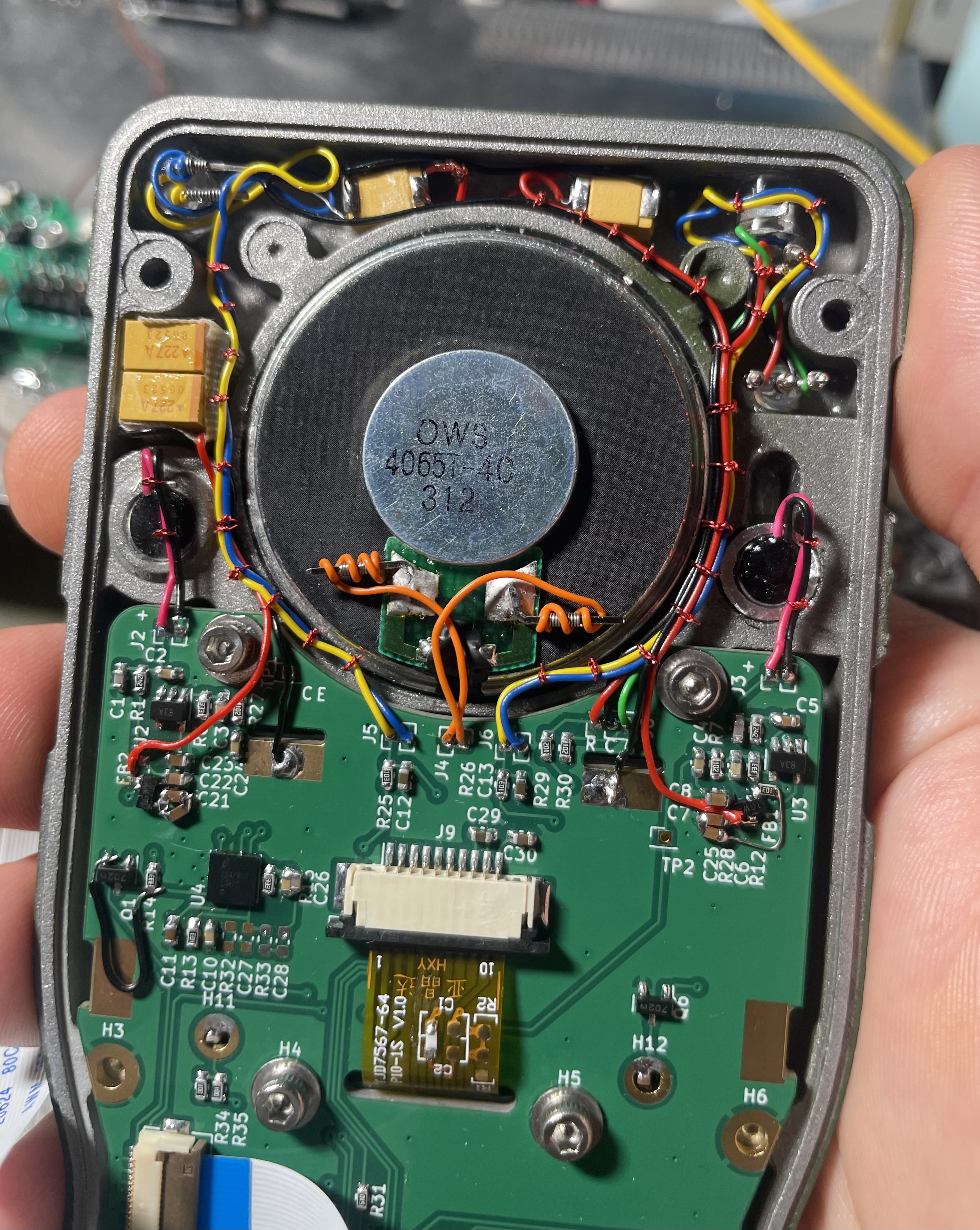
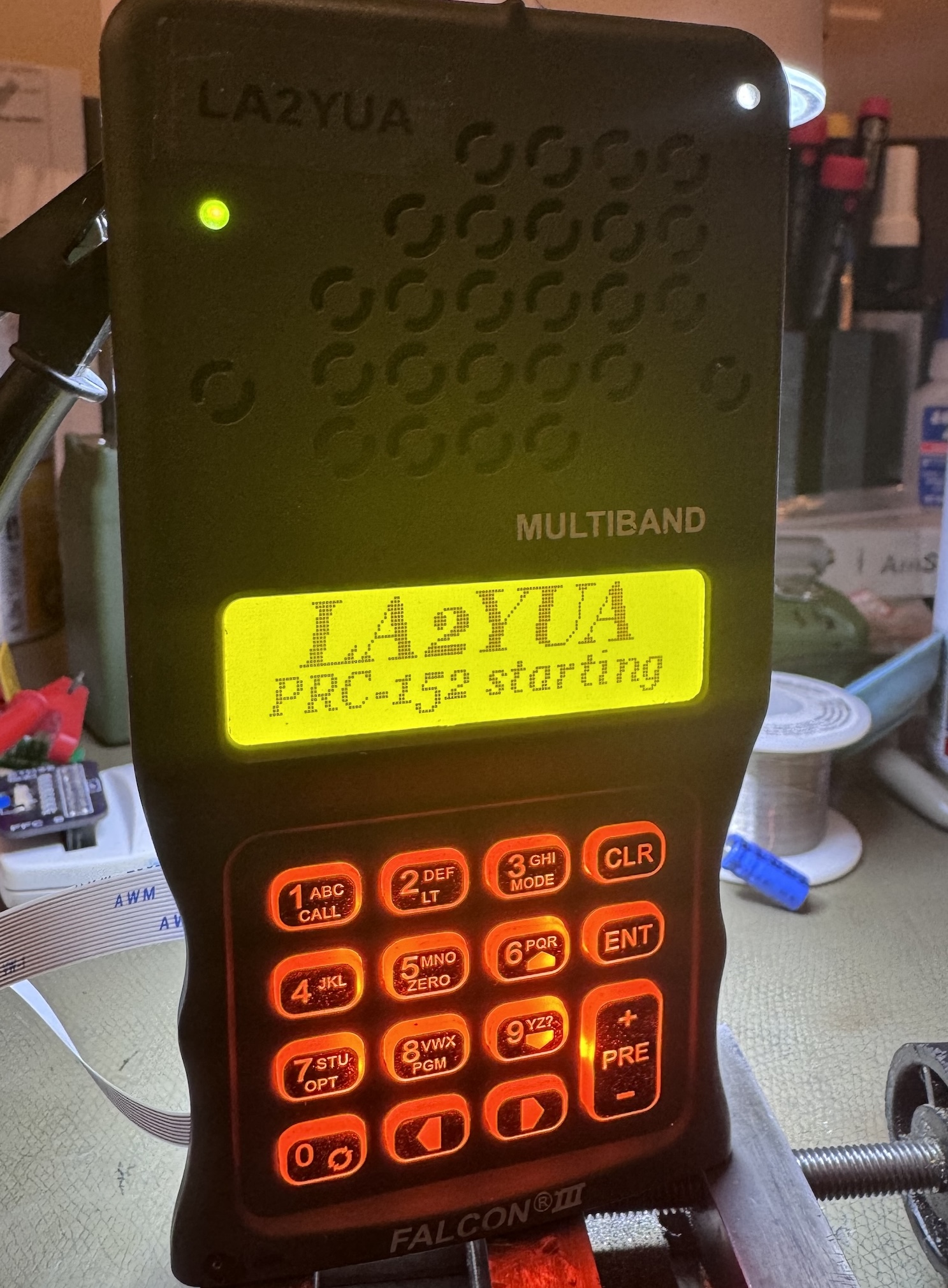
The new PCB actually worked out just fine, though it took me almost a year to bother getting the LCD code working. I decided to also use orange LED's for the keypad backlight, and I added a red/green LED and light sensors to the chassis.
The biggest issue faced here was that the 2 W capable speaker power amplifier combined with FFC 5 V supply resulted in severe voltage drops when driving the speaker hard. I ended up modifying the design with around 1 mF of bypass capacitance (glued into the casting) to keep the 5 V rail stable, and I added capacitance multipliers to the 5 V supplies for the two microphone preamplifiers.
Once I started the only processor issue was that I had misidentified Data/Command and the enable line, which caused some head scratching. Fortunately this was easily swapped around in software.
I also revised the phototransistor sensors range, these are used to dim all the LED's using PWM.
Battery Interface (Finished)
The battery interface was made twice, the first one being kind of a rushed design made to fit into a system design that then moved on.
It had a linear slow charger IC, active ORing between internal and external power, and a 5 V power supply intended as the always-on regulator.
I later re-spun the board, making some changes:
- Ditched the 5 V regulator
- Kept the active OR circuitry
- Added a boost regulator powered only off the external supply input, allowing the battery to charge off lower input voltages
- Kept the slow linear charger
Ideally I would integrate USB-C PD capable charging circuitry, but there simply wasn't room for this.
The design is relatively simple and allows powering off an external ~12-13 V supply with seamless battery switching. When powered externally, the battery will charge. If the radio is off, the battery will be able to charge even with lower voltages.
Initial Processor Board Concept (Abandoned)
The processor board was initially meant to use a Digi SoM device, but this turned out to be very hard to get as an individual. I then later changed tactics and made a design based on a Raspberry Pi CM4.
The Digi SoM EVM was ordered, and I used this with two RTL-SDR dongles to make a prototype AM/FM receiver, using the redesigned front panel as a speaker, and the Tri KDU as a serial display. This was fairly successful on a technical level, the performance of the AM/FM receiver was top notch, so the code will hopefully be reused.
This design would have integrated 4⨉RTL-SDR receivers, a LoRa modem, a short wave AM/SSB receiver, and a GNSS receiver. Additionally, it would have included wired Ethernet on the side connector.
I did completely route the design and I was fairly close to ordering it, but upon reflection I decided that the software work to support this as a practical radio would be enormous.
I was also painting myself into a corner wrt. the transmitter side – the idea was to use a CATV hybrid as a power amplifier without any output filtering. Then a number of different simultaneous carriers could be transmitted at the same time. I realised that actually making this RF board would be very challenging.
The parts purchased for this concept are planned to be reused for an entirely different concept.
The Requirements Set
I spent the early part of 2024 rethinking the concept. I concluded that making a one-off design of this complexity would be pretty wasteful. As such it was decided that the design had to be somewhat flexible to let me repackage the radio boards as e.g. base station radios.
I had some vague requirements for this project, so I'll try to summarise them here:
- Has to make the PRC-152 radio useful, and utilise the capabilities the large chassis and battery offers
- Has to be possible to hook up to an external RF-5980 speaker and Falcon II KDU with an interface board for the base station variant
- Great audio with internal and external devices
- Including RX AGC and noise reduction for AM/FM
- AM receive/FM transceive, 118-174 and 400-470 MHz min frequency coverage
- Target: DMR transceive for VHF/UHF
- Minimum 2 W RF output power
- Minimum of 3 receiver channels for any mode to support scanning
- Capable of full duplex VHF/UHF operation
- GNSS receiver for APRS/Meshtastic beaconing and time synchronisation
- APRS transceiver
- 6-pin handset interface supporting powered headsets and a V60 PTT (digital)
- Initially I planned to use 5 V power like the Tri, but changed this to 12 V nominal later
- For base station: support for 2-4 external analog radios
Some nice to have requirements also appeared:
- Short-wave receiver with minimum AM/SSB, when paired with appropriate antenna
- Wi-Fi remote control when at base (web interface to program channels)
- Meshtastic 868 MHz support
- Bluetooth audio support
- Interface between Radio and Control board should be compatible with a TLK1501 SERDES IC
The New Concept
My new concept started at the radio board end. I elected to put as much as possible into the radio side then the control board would have to fill the rest in.
For the base station configuration there will be at least 2-3 additional circuit boards to support e.g. the SERDES routing and things such as external analog radio interfaces. These functions will hook up to the future processor board, which has not been fully designed yet.
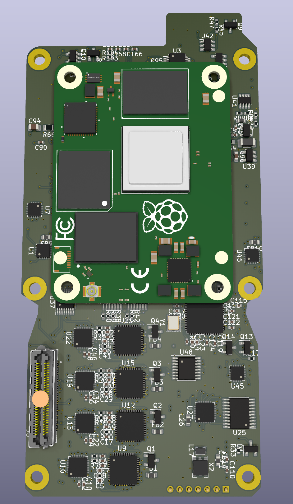
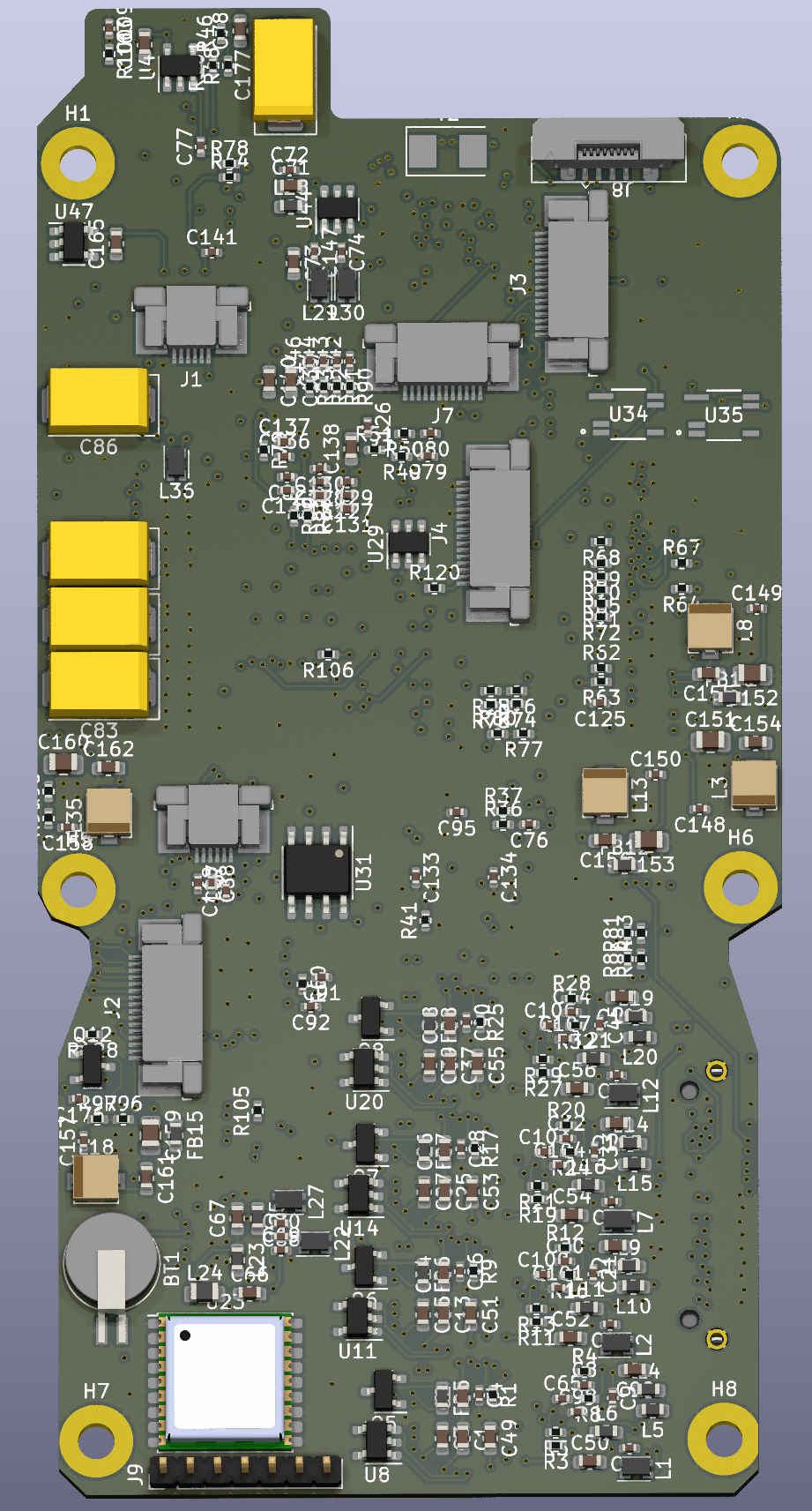
RF Board (Future Work)
To support FM receiver for e.g. APRS, I plan to use 4 pcs. RDA1846S SDR receivers (the core of a Baofeng UV-5R). An option to use the RDA1846 transmitter directly (no PA) is also planned, to allow for ~1-10 mW very low power transmission, and possibly full duplex operation over short distances.
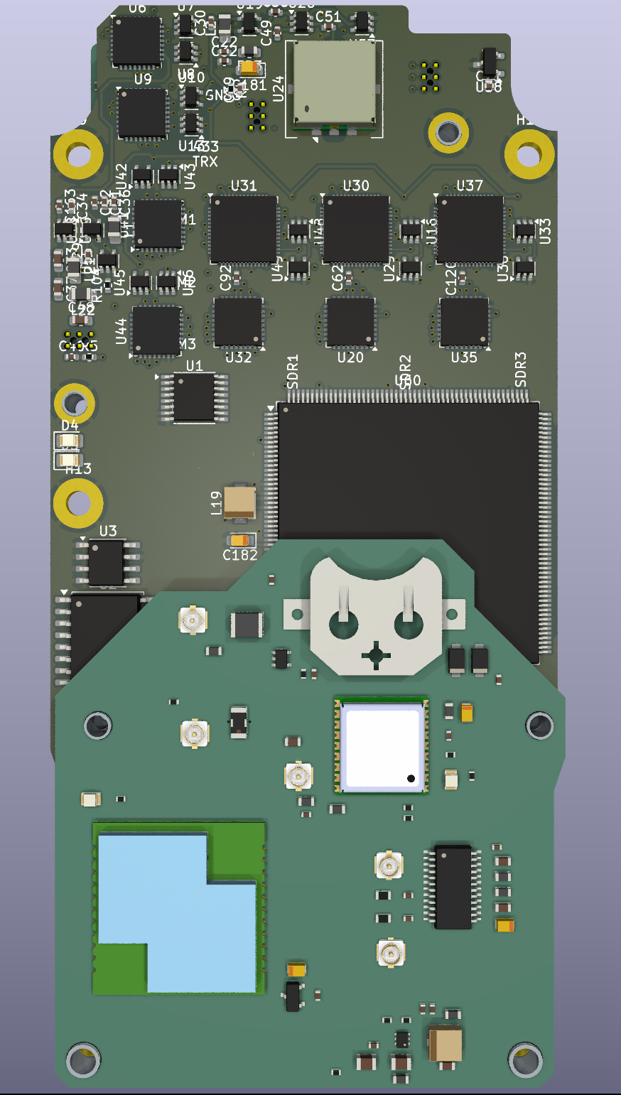
The current working model of the board is shown above, with the ISM and transmitter board (not visible) modelled in.
To support AM receive, the plan is to use AK2401 SDR receivers. These devices include a zero-IF complex downconverter and high performance ADC, and I plan to connect them to a DSP/processor using I2S to process the I/Q signal for AM/FM/other demodulation.
The processor is planned to be a STM32H7 dual core (M7/M4) device, with the big core doing the DSP work and the M4 doing the housekeeping.
DMR/FM Radio Board (Planned)
I've elected to use niceRF modules for the transceivers, and two options are suitable here. The DMR818S can be used for DMR for VHF/UHF. For initial testing I plan to use SA868S modules instead, which are FM only but otherwise similar, and cheaper.
As a future upgrade I may try to make my own SDR transmitter in place of using the modules, hopefully as a swappable module. I'll try to add some signals to the interface that may be useful there, such as a clock signal for a synthesizer.
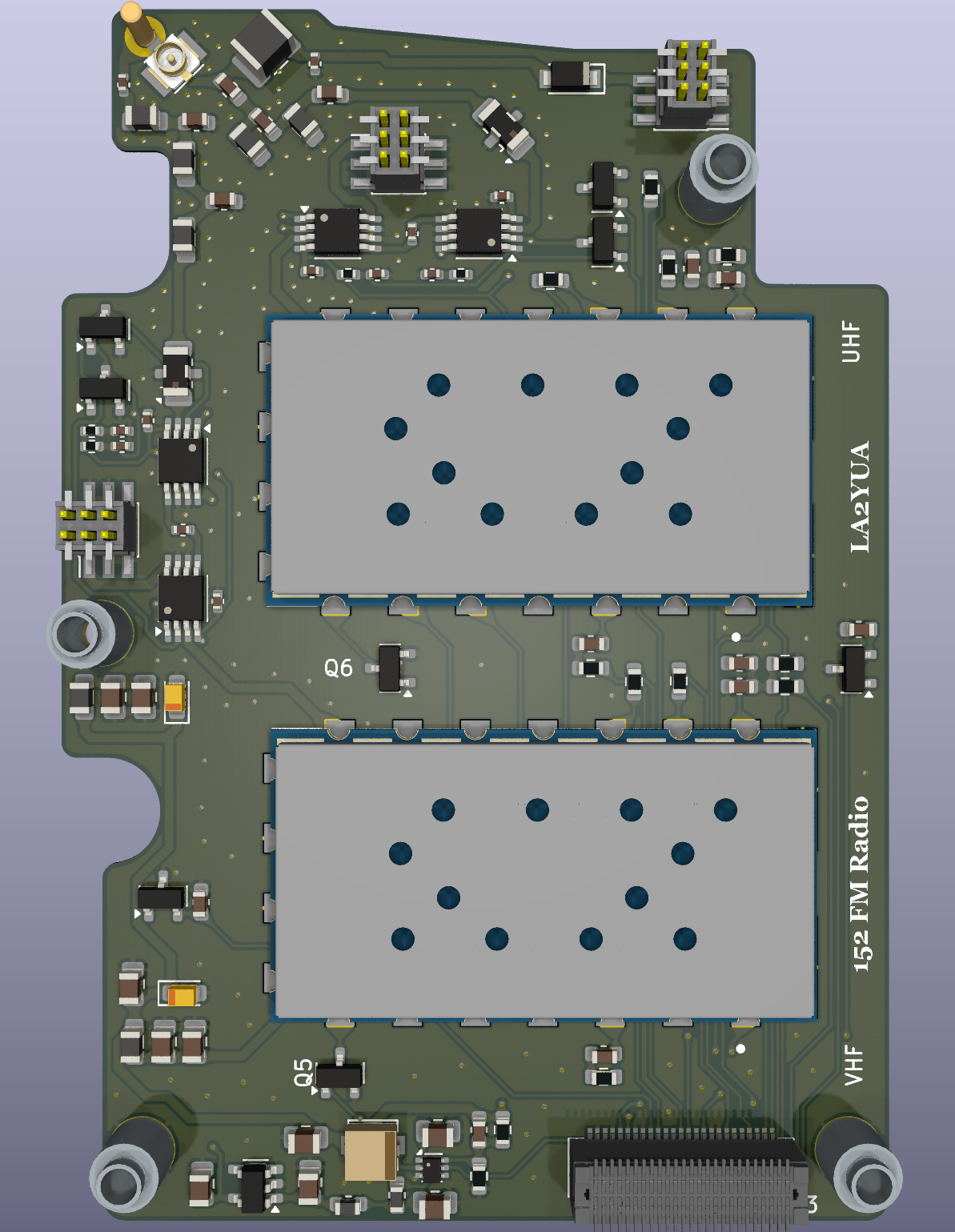
These modules along with the antenna interface will be made as a separate pluggable mezzanine board. This will be mounted to the RF board with a cooling interface to the center casting of the radio.
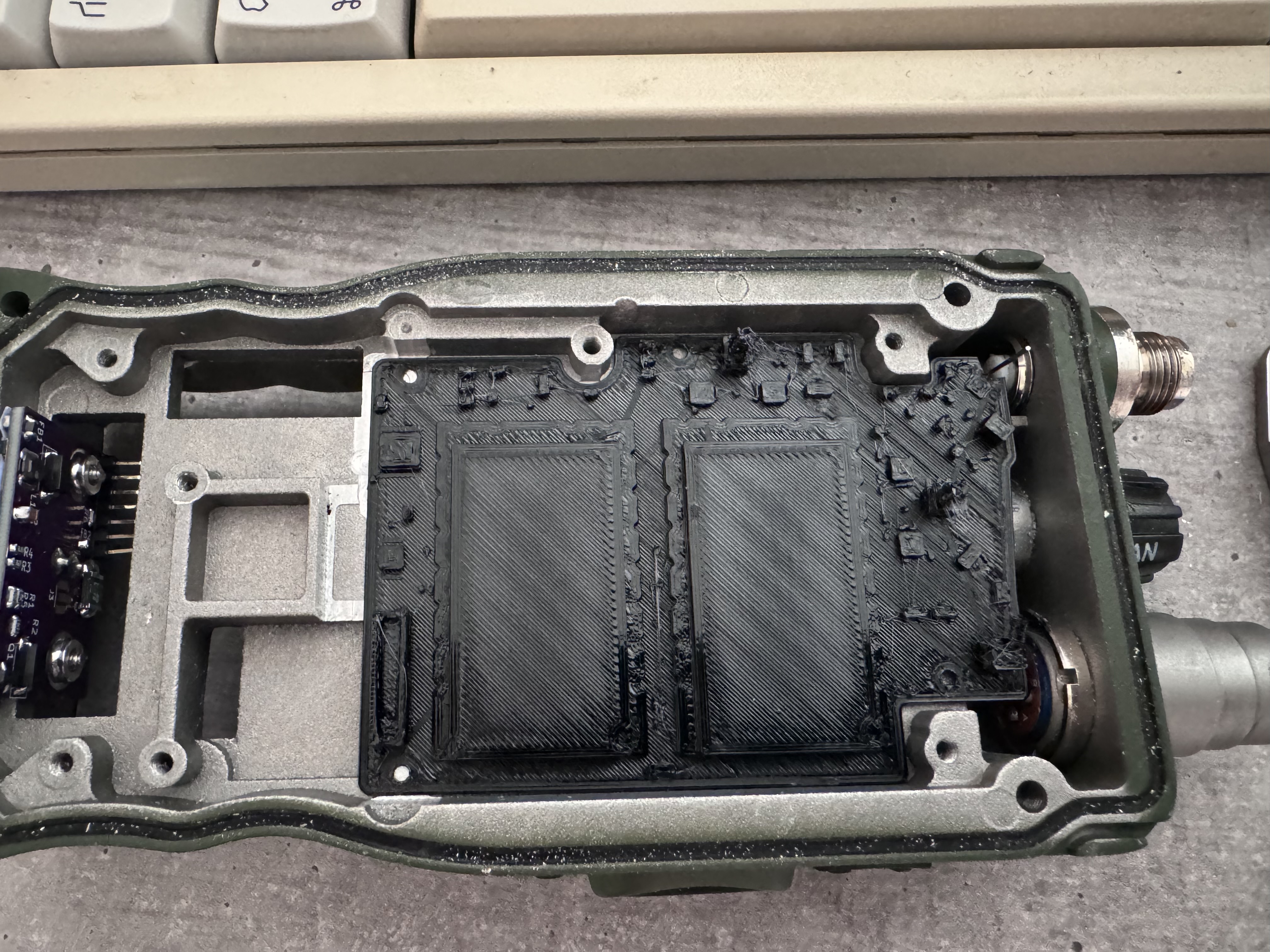
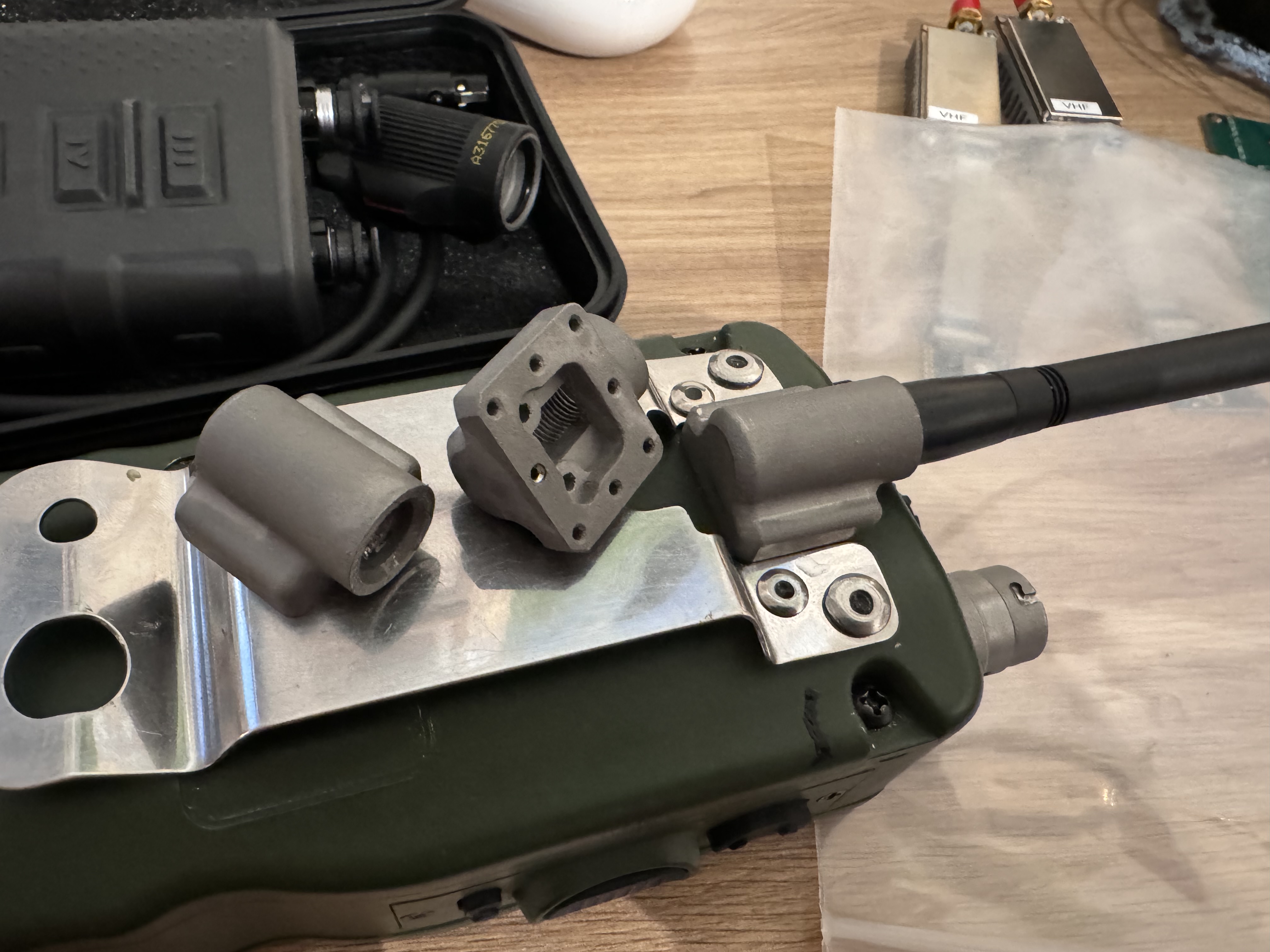
This board is planned manufactured summer/autumn 2024. Above a 3D printed model of the PCB is test fitted after machining the central casting of the radio to accept it.
I've found that 3D printing models of circuit boards is a very good way to match more complex geometries.
ISM Board (Planned)
To support Meshtastic, GPS, and Shortwave reception, a second mezzanine on the other side of the RF board will contain the required hardware for these functions.
The Heltec HT-CT62 LoRa module will be used for Meshtastic, a Si4735 receiver for short wave, and a uBlox MAX-M10S will be the GNSS receiver. Additionally, I had room for a RTC battery on this board.
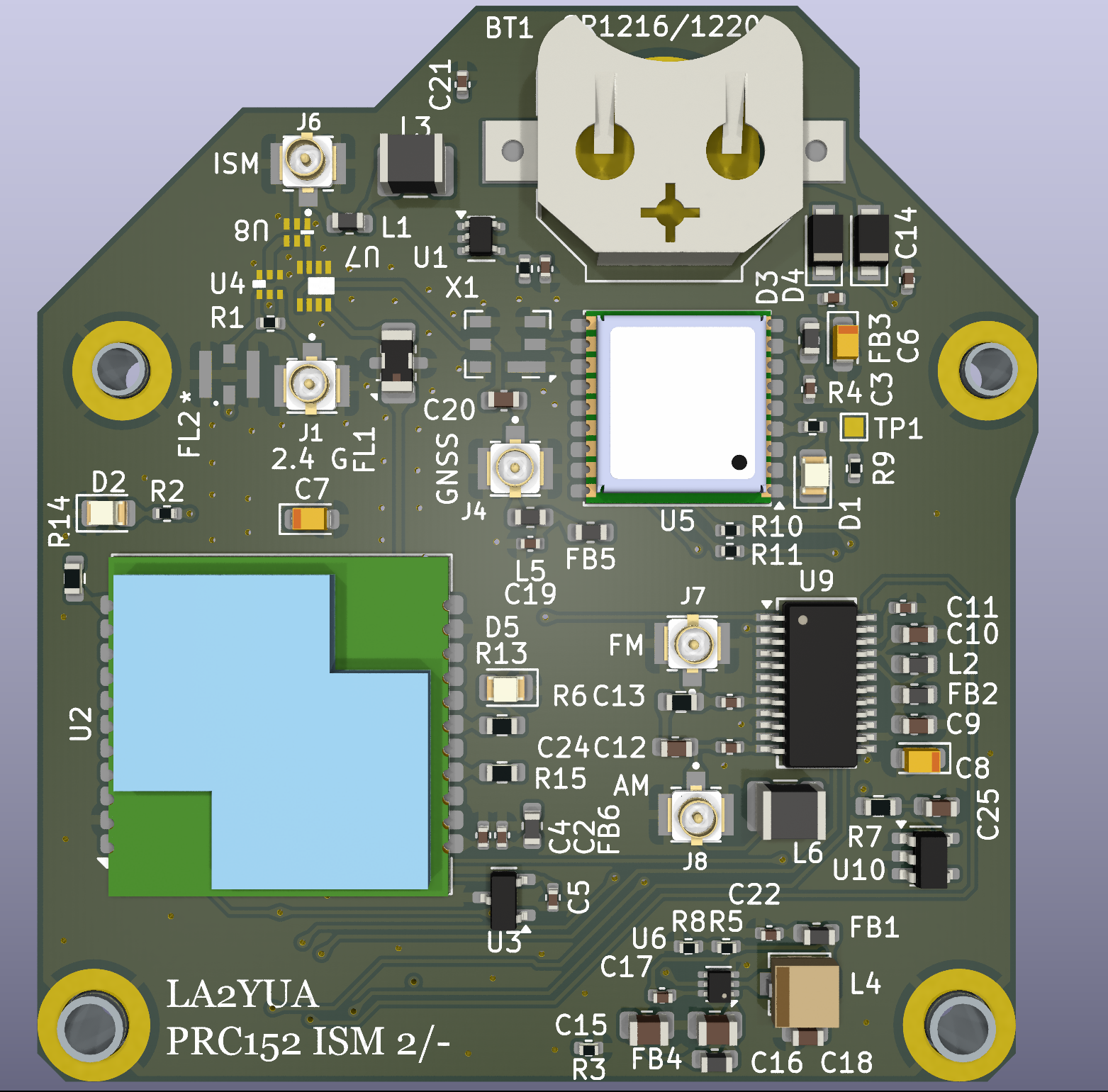
A second antenna interface will be used here, and a new antenna mount was retrofitted to the radio back shell. This was 3D printed out of stainless steel, which was a delight to put threads into. These were made by JLC, and the quality was quite good.
I plan to make this board in summer 2024.
Processor (Future Work)
For the processor board, the plan is to use a Raspberry Pi Zero W (version 1). This is the slowest but also literally the cheapest Linux capable processor module available. Given that the bulk of the signal processing will be done in the H7 MPU, and I plan to use a SigmaDSP (likely ADAU1442) for audio processing, the main job of the Zero will be housekeeping. Mainly, the plan is to hook up SPI for DSP control, and a USB hub with CH340 serial converters to talk to other devices.
The Zero W has the benefit of being very low power and relatively compact. I will make an interposer board to make mounting more convenient.
Additionally, I am trying to make it feasible to put a SERDES IC between the RF and control board. This would allow remote mounting of the actual radios, with a fiber optic link between it and the control board. The main restriction there is some potential clocking issues and the added delay for the I2S audio links, but I consider these to be solvable problems.
External Speaker, RF-5980 (Finished)
Since I now knew I wanted to make more than a single radio out of this design, the extra radios would need their own speakers and displays.
I was able to find a couple of Harris RF-5980 powered speakers with dual handset ports for relatively little money on eBay. These were determined to be a good base for the non-portable radio variants. At the time of writing I have two in perfect condition, and am looking for a third since I made 3 electronics sets.
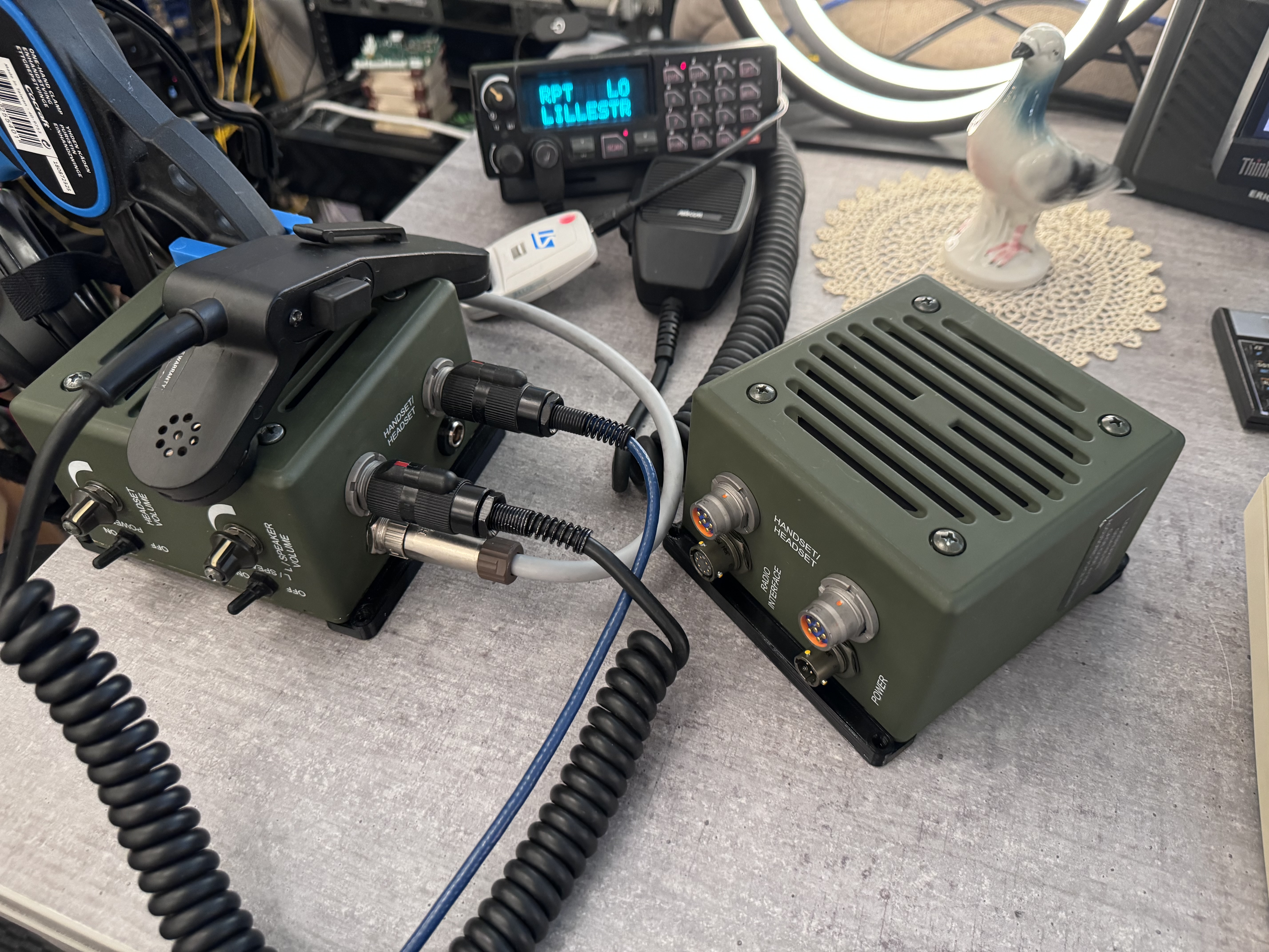
The speaker itself has a radio interface, a power interface, dual handset ports, a speaker, and volume and on/off controls for both speaker and handsets.
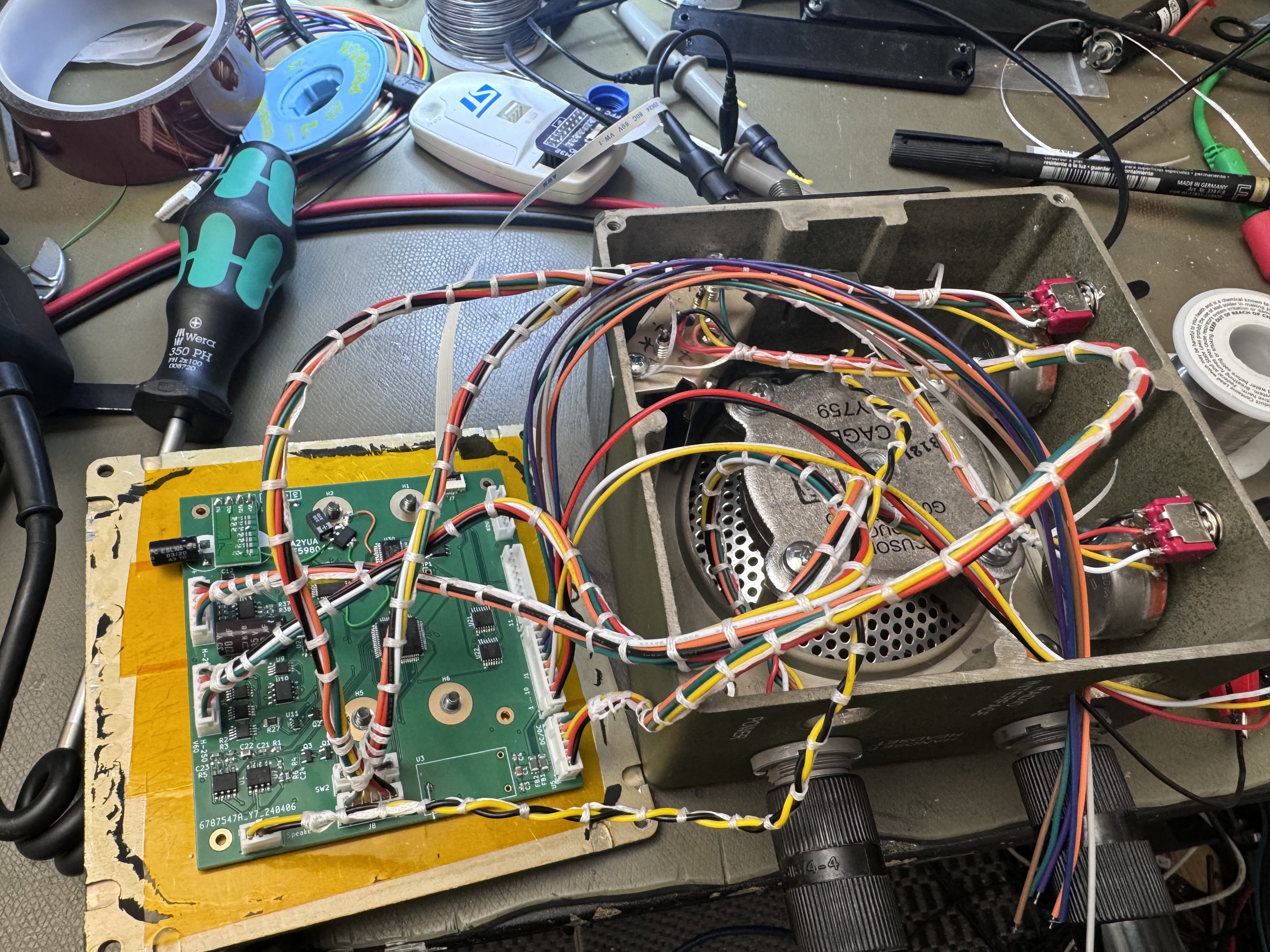
I made new electronics for these speakers, adding a processor, a DSP (ADAU1701) to process audio, digital audio in/out, and a serial port for control. Additionally, I added a V-60 interface to one of the handset ports, and repurposed the original power plug hole to be a KDU interface with serial port and power.
The build went pretty well, the major issues I had were:
- Incorrectly measured mounting holes – drilled two new holes and plugged the old ones
- The WM8804 S/PDIF transceiver is hard to use in full duplex, see linked article.
- Some strapping to make the ADAU1701 send and receive data based on the WM8804 I2S clocks (need to hook up both input & output LRCLK/BCLK pins)
- Turns out the ADAU1701 1.8 V supply needs to be fairly beefy, so an LM1117 had to be modded in to drive it
- Also turns out that isolated DC/DC's are pretty noisy, so I had to add 78/7912's to the DC/DC converter output to quiet down the supplies
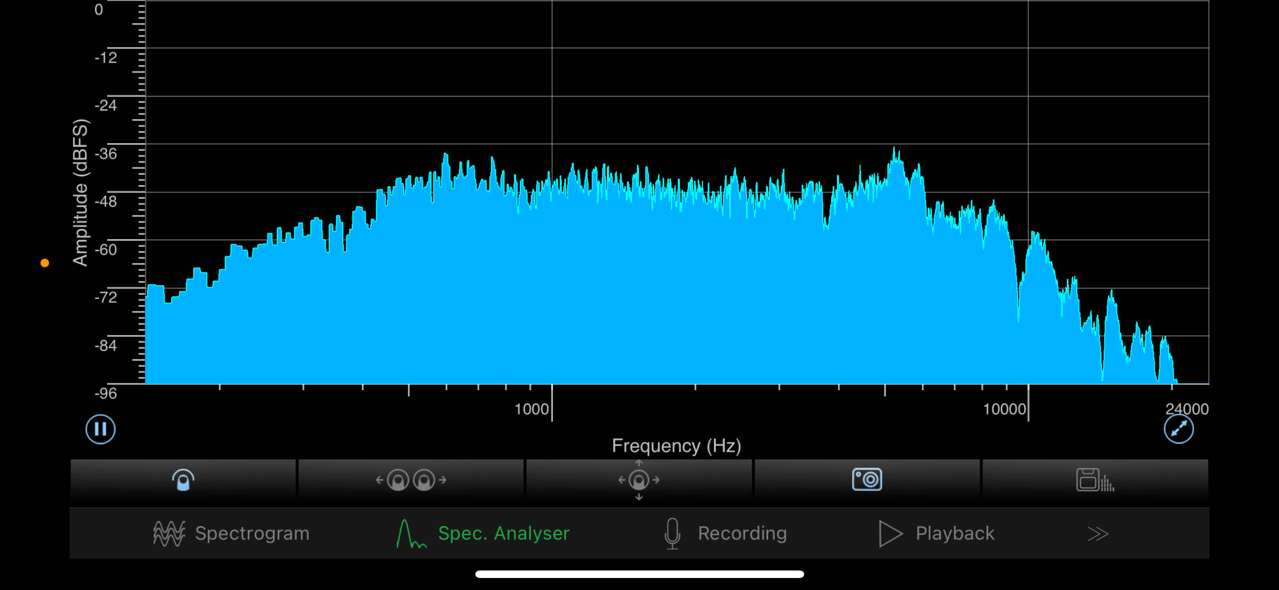
It has been commented that a speaker has two wires, but this design only needs twenty. As seen above, the speaker's on-axis response is not all that bad.
The V60 interface is software selectable, and just uses a set of analog switches to select between the analog mic/speaker signals and the digital lines. The S/PDIF audio to/from the V60 is simply passed through the speaker, while the serial port is routed to the MCU in the speaker which can pass messages as needed.
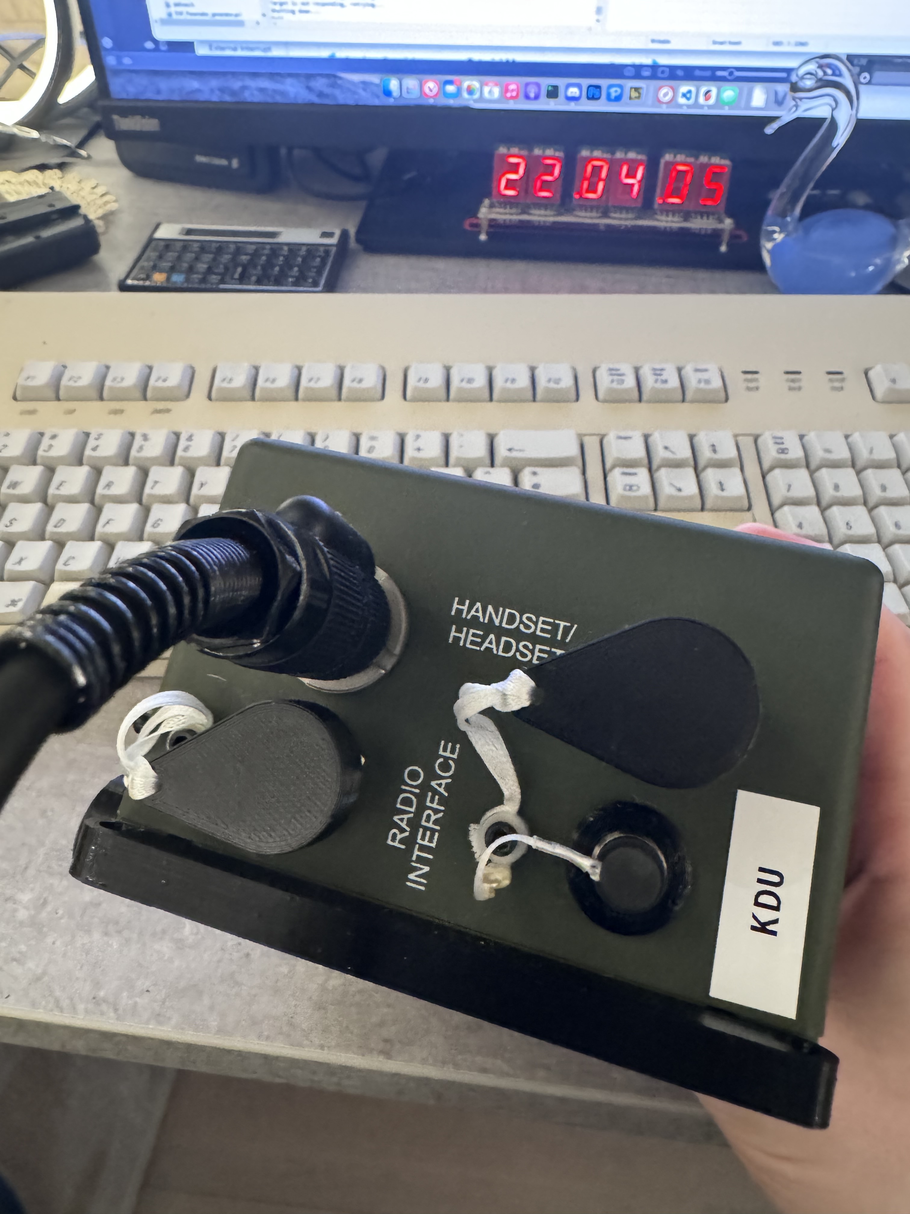
Similarly, the KDU interface has the serial interface routed through the speaker MCU. I chose to use a 6 pin MiniXLR for the KDU. This is a low cost shielded connector that fit the existing holes with a simple 3D printed bushing.
The radio interface uses a 20 pin Hirose LF13 plug, which was the best option for something that fits in the existing holes and isn't crazy expensive. All the interfaces are differential RS-422 or similar, and I had some shielded twisted pair industrial cable sitting around that was used to make interface cabling.
- Isolated 24 V supply
- High speed serial port (~1 Mbit⁄s)
- S/PDIF TX/RX, speaker
- S/PDIF TX/RX, V60
- Reset & Bootmode
The radio side is simply a 25 pin D-Sub, for simplicity's and costs's sake.
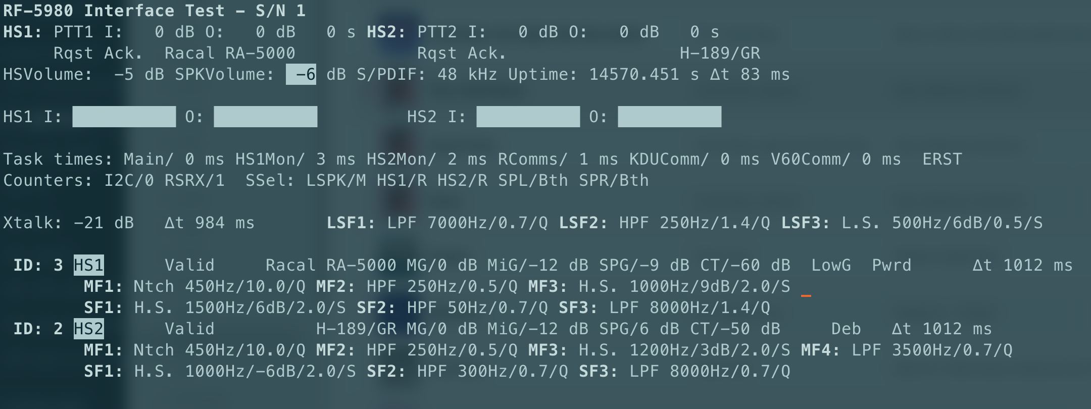
A Pi Pico based board was made to act as an interface tester for the speaker, I probably won't use the Pico again except for special circumstances. Above an interface tester program is shown, which shows the state of the speaker control and selected audio profile. This program can talk directly to the speaker using a RS-422 adapter, or (like above) can talk at reduced rate through the Pico USB serial interface.
The interface board was over all a success though, I added V60 style mini-XLR connectors that lets me connect an analog radio. Currently this is in operation with an Ericsson Orion for transmit/receive and an Icom IC-A6 airband transceiver (no transmit, through fiber optic).
The RF-5980 is considered finished aside from assembly of the additional units. Software-wise the core functionality is finished, but support for e.g. KDU/V60 serial data routing and polishing of the serial interface is still needed.
I also made 3D printed TPU dust covers for the connectors, this saved quite a lot of money!
KDU (Assembled)
I previously wrote about the Falcon II KDU that is available quite inexpensively on eBay at the time of writing.
See my separate devlog on this: Devlog 2 — The Falcon II KDU
This device is quite cute, and I decided that this would be a good HMI device to use with the base station radio concept. Having worked out the pinout, adding the electrical interface to the RF-5980 speaker was relatively simple.
While I did consider trying to reverse-engineer the software in the KDU, I didn't have the appropriate programmer to read the original flash code. I was also scared by the enormous size of the flash, fearing that it may contain an entire operating system and a million layers of abstraction.
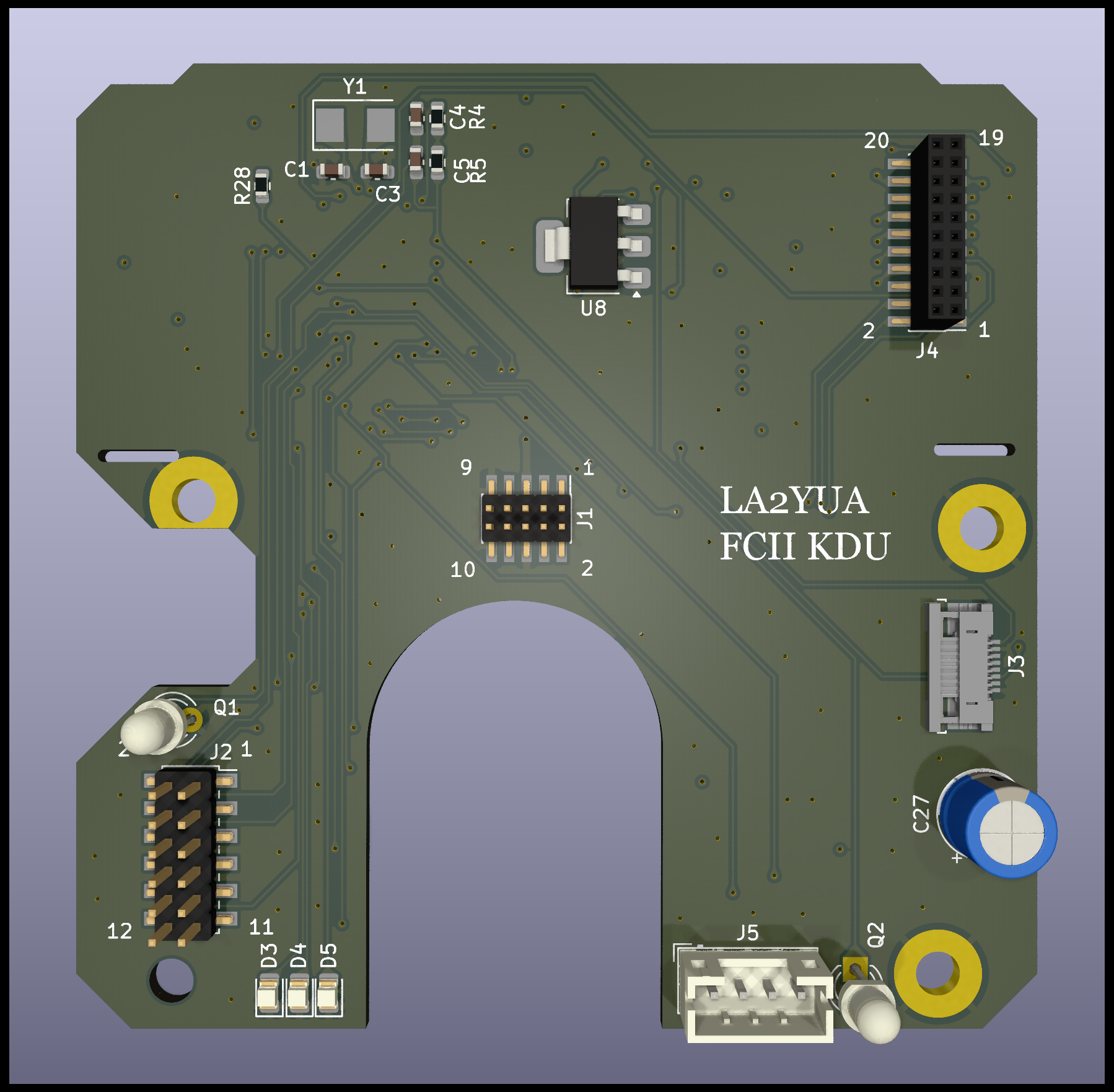
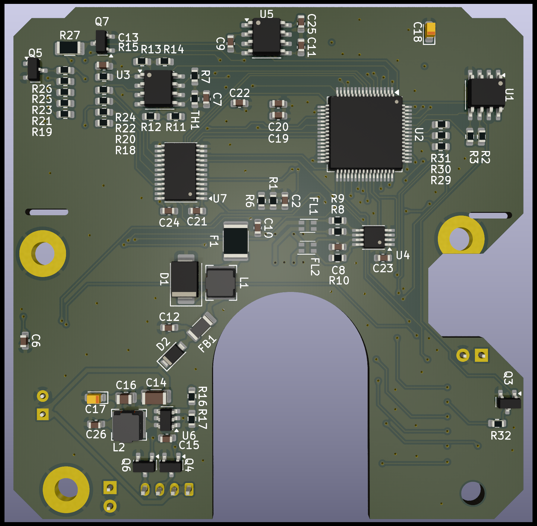
Further, redoing the electronics means I can make my own interface, hopefully making the TRI KDU, the FCII KDU, and the internal PRC-152 keypad module very similar in capabilities and software interfaces.
Since this design is very neat, I ended up buying five of these in total. I figure I can use these for other things later.
TRI KDU (On order)
The TRI KDU was discussed in the PRC-152 article. I managed to pry it open, and made a new electronics set here as well.
There wasn't much wrong with the original design, but since the processor used by the Tri device wasn't pin compatible with my STM32 devices I ended up with a respin. Further, I wanted light sensors, PWM dimming, and a more flexible software interface to support additional display modes.
Additionally, I added a DC/DC converter on the input to support 8-24 V power.
More details to be added in a future entry since these parts are on order.
V60 PTT/AMP Headset (On order)
The V60 PTT and FCS AMP headset combo was also designed into the system. The V60 PTT is a 4-way PTT with 3 radio interfaces.

I redesigned the PTT circuitry entirely, with a similar feature set to the RF-5980 speaker. The main radio interface is now a serial port and S/PDIF audio going both ways. The original V60 design was completed before making the RF-5980 circuitry, and I used the RF-5980 design as a prototype for the more compact V60 system.
A number of minor issues were found in the RF-5980, and I have addressed these in the V60 design so hopefully I won't have as many issues this time.
The V60 PTT then has the main digital I/O, the headset interface circuitry, and adds two generic radio interfaces.
These generic interfaces will contain speaker audio inputs, microphone (simulated) outputs, PTT out, and retransmit (RT) in. RT is basically a squelch-output that is supported on some radios including the PRC-152. This can be used to make a simple radio relay with two radios, interconnecting the RT/PTT's both ways. This interface is also part of the RF-5980 interface test board.
With four PTT buttons, PTT I/II is nominally the PRC-152 A/B channel, with the III and IV being the two generic radios. There is also an uncommitted button.
More details will be added to a separate log entry, once I have working boards.
AK2401 Test Board (Planned)
Since the RF board is intended to use AK2401 SDR receivers for e.g. AM receive, I need to prototype this to ensure it will work as intended. Of particular concern is the I2S hookup for the AK2401 digital I/Q data. I have previously found the STM32F1 and F3's I2S peripheral to be largely ornamental, so I'm hoping that the H7 has something that actually works. Previous testing of the SAI peripheral indicates that this does actually do what it's supposed to, but the SAI's will be used for other functions.
The plan here is to make a board with an AK2401 and an ADF4351 synthesizer. Two of these will probably be hooked up to a STM32H745 Nucleo board as a proof of concept. This will also let me start working on the software demodulators.
I'll probably build this as a separate project and make the test assembly into a standalone AM/FM receiver with e.g. a Falcon II KDU interface and internal speaker. While this will be obsoleted by the PRC-152 when finished, it will be useful in the mean time, and can probably find a home somewhere.
(2024/08): The AK2401's are on hold, pending evaluation of using EFR32 Sub-GHz receivers instead — these are lower cost, seem to offer 16-bit I/Q data, and include a 40 MHz Cortex-M4F core that should be sufficient for demodulation. Will return to this in a future article.