Magnetic Project Overview
This is an overview of my documentation for the Magnetic AB/Ericsson NMT 450 base station transceiver system.


This project started out as a simple “hack it to make it work” sort of job, which I succeeded at in 2014. The receiver and transmitter were operational from 2014 to 2016 running an initial half-duplex D-Star repeater, then later a dual antenna full duplex system.
My current plan is to improve on this original system by reusing the better parts of the system, and replacing the rest with custom designed circuitry to implement either a very good 50W radio system, or a full duplex repeater stack suitable for modern digital modes as well as high end analog performance.
Table of Contents
List of articles
| System Overview | |||
| All in series | |||
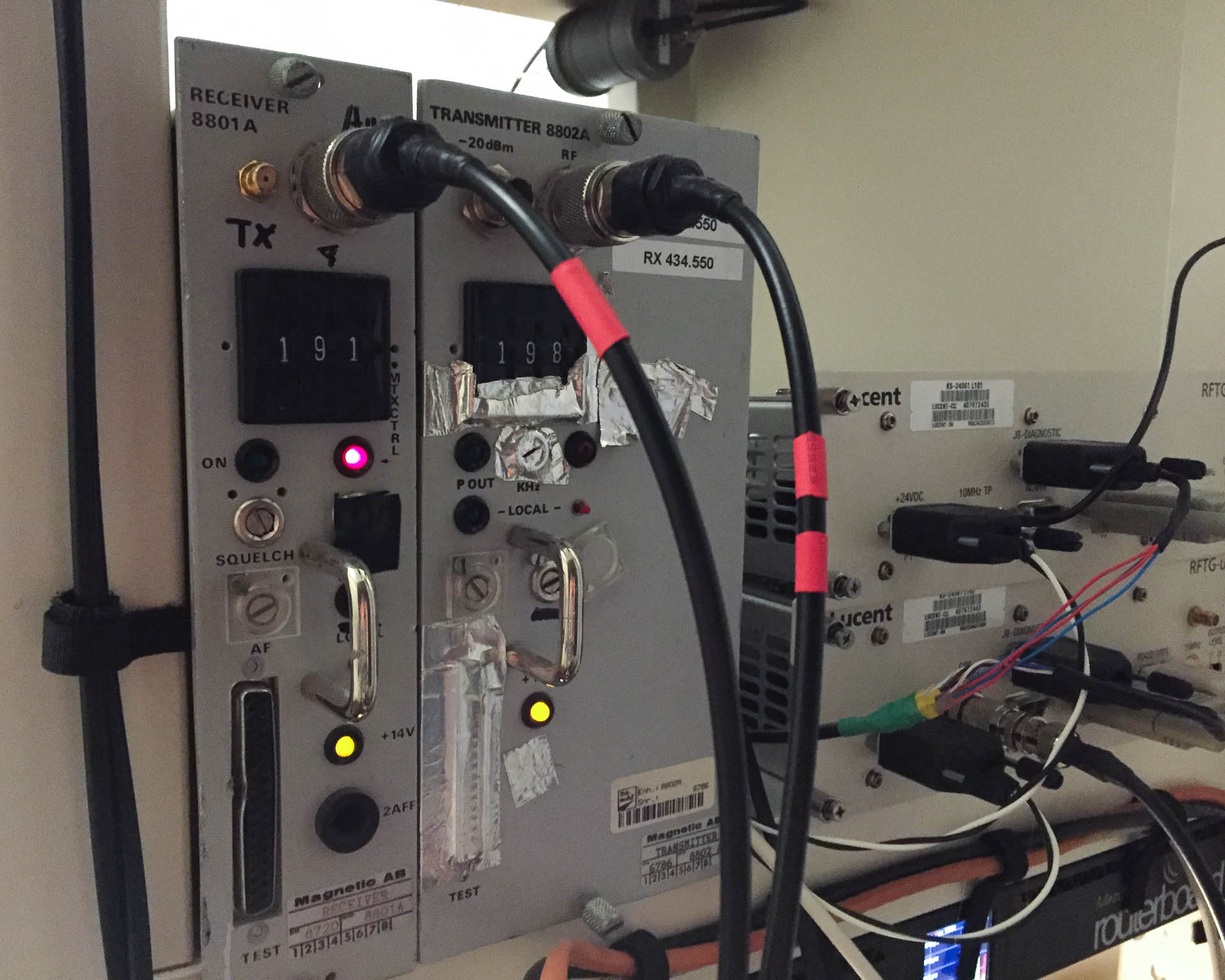
| 8801A Receiver | |||
| 8802A Transmitter | |||
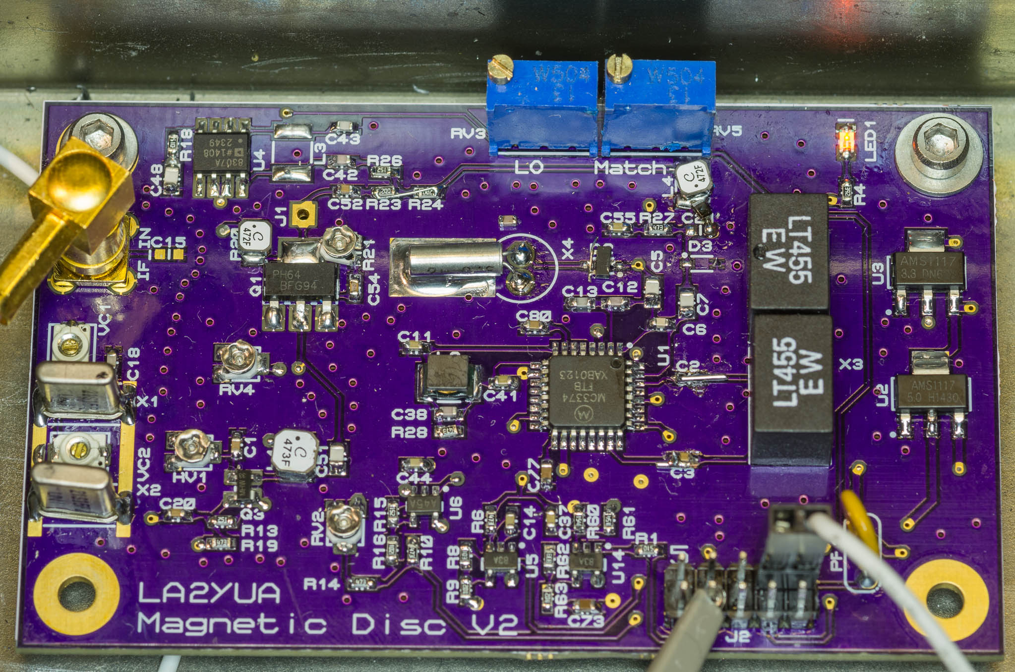
| LA2YUA 8801A Receiver | |||
| LA2YUA 8802A Transmitter | |||
System Overview
NMT 450 was a fairly advanced 1G cellular phone network, operational from ca. 1981 to ~2004 or so though it was largely displaced by GSM networks by the late 90's. The system replaced earlier “0G” networks such as OLT and an OLT like UHF system. The system was a fully automatic roaming system using full duplex FM radios operating in the 450 and 460 MHz bands with a 10 MHz duplex split. Deviation was 5 kHz, as usual for FM systems of the era.
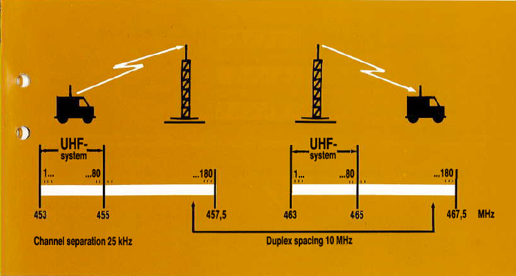
As shown below the system used 180 channels with talk-in at the low side and BS TX at the high side. The “UHF System” referred to in the figure is a manual UHF phone network that I haven’t found much information about except for some fellow hams mentioning it existed. This system was expected to be abandoned by 1987 to free up the lower 80 channels for NMT use.
I suspect that system was put in place as a stop gap measure due to a lack of channels for the VHF OLT system in cities; with the introduction of 180 channels of NMT along with what Ericsson proudly called the “small cell concept,” congestion issues were FIXED FOREVER (until around 1985).
Mobile unit power was up to 15W, while base stations had around 50W from each transmitter with some combiner loss. A power reduction function was mandatory for mobile units to reduce near-far interference, this was controlled by the base station which would control a dedicated power measurement receiver to measure RF power for each active channel in order to determine the required power level.
Interestingly, the smallest NMT 450 phone ever built was a Nokia about the side of a 3210 (and no, I’m not confusing it with NMT 900 phones, I actually have the 450 version somewhere). Quite an achievement packing a sufficiently good band pass filter into such a small package, but then nearly 20 years of development wasn’t for nothing. Portable (as opposed to luggable) units were fortunately not required to have 15 W output power, though all other parameters would normally have to be met.
A lot of the original system documentation and requirement specifications are available on the internet, such as here: http://download.eversberg.eu/mobilfunk/NMT-Dokus/
Allegedly this system was the most advanced 1G network in the world when it was launched, several features were new, including:
- Automatic dialing and channel selection
- Automatic billing
- Automatic handover
- International roaming (inside Scandinavia and neighbouring countries; some countries that later adopted the system could not roam to the Scandinavian system and vice versa)
- Fully digital communication system (in band, 1200 baud FFSK)
- SMS support
- Half true; the latest specification for NMT 450 released in 1995 did specify how this should be implemented but I don’t think any of the Scandinavian providers or any of the phone makers supported it.
The system required a digital computer in each mobile unit, although the system was nominally designed to keep the cost of phones down.
I believe the AMPS system used by American companies as well as the UK variant of this system was introduced slightly later and included all of these features. These systems used the 800-900 MHz band for higher channel density. This was later copied for NMT 900 which was basically the NMT 450 specification with search+replace applied liberally after they realised their 300 k+ predicated subscriber count made placing a call in cities nearly impossible. Imagine a city of 500 k+ inhabitants covered by less than 100 phone lines in the late 1980s.
It should be noted that the NMT 450 system was very well suited to rural Norwegian use since the longer wavelength gave far better coverage in various fjords and valleys. This coverage level was not realistically matched until the 2010s when LTE 800 was rolled out to even fairly remote areas.
Another practical advantage was the high output power and general car-mounted usage of the phones which required fixed roof mounted antennas that usually had some gain. A Nokia GSM phone with 2 W ERP and at most a ¼ 𝛌 wave whip sitting in a dash mount really had no chance of matching that.
The typical layout of a mobile phone is shown in the figure below:
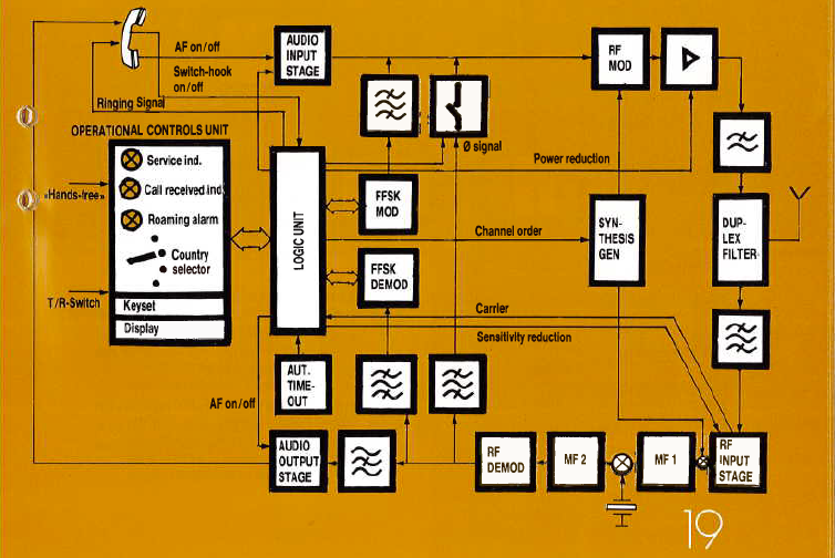
Note the “Ø” signal; this is a continuous tone transmitted by the base station which is relayed through the phone unit and measured in the base station. This signal is used to measure the signal quality of the link and during handover. A compander/expander could also be used to improve dynamic range if supported by the phone and base station, the latest revision of the NMT 450 specification also allowed for a voice scrambler over the air.
Several manufacturers made NMT 450 equipment including:
- Ericsson (notably the Hotline series)
- Nokia
- Mobira
- Matsushita (Panasonic)
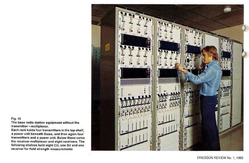
The base station equipment I have would have been put in a rack with 8-16 sets of receivers and transmitter + support equipment. The layout probably looked a lot like this:
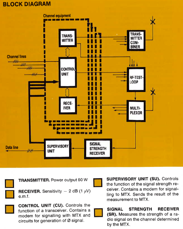
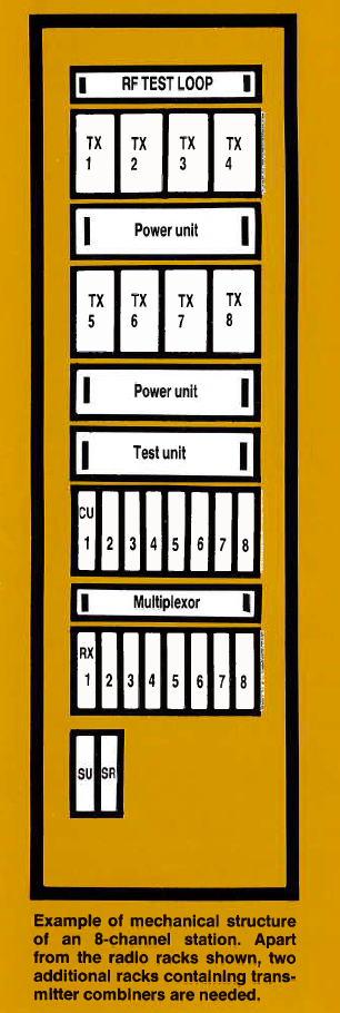
The layout would use a band pass filter+splitter to run up to 8 receivers off the same receiver antenna, and a power combiner+filter to combine the transmitters. I’m not sure if single antenna systems were used or if multiple antennas were used here. It is likely these were either cavity or helical filters.
Helical filters and dielectric resonator filters were common in the mobile unit combiners, which required fairly good performance to achieve the required sensitivity, these filters are worth salvaging as they can often be retuned to 433 MHz.
The following figure in Ericsson Review suggests single antenna systems were used. Note also the power measurement receiver. Not shown below is the test generator system included in each rack to test the RF signal path.
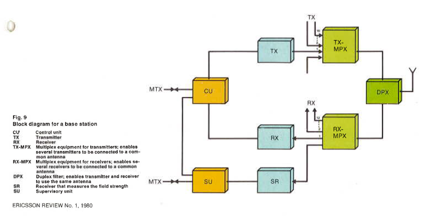
An article in Ericsson Review in 1980 had a picture of a typical base station setup; I believe this is an earlier model of my units due to some differences in how the front panels look (notably, there’s no large BCD channel selector). My units are all from around 1986.