The 8801A Receiver
The 8801A receiver is very similar to the F955 receiver, so a lot of the technical documentation can be referenced: http://www.jancorver.org/en/ombouw/ericsson/f955/
The main manual is in Dutch, but it’s still somewhat understandable due to the excellent diagrams drawn by PA0IB.
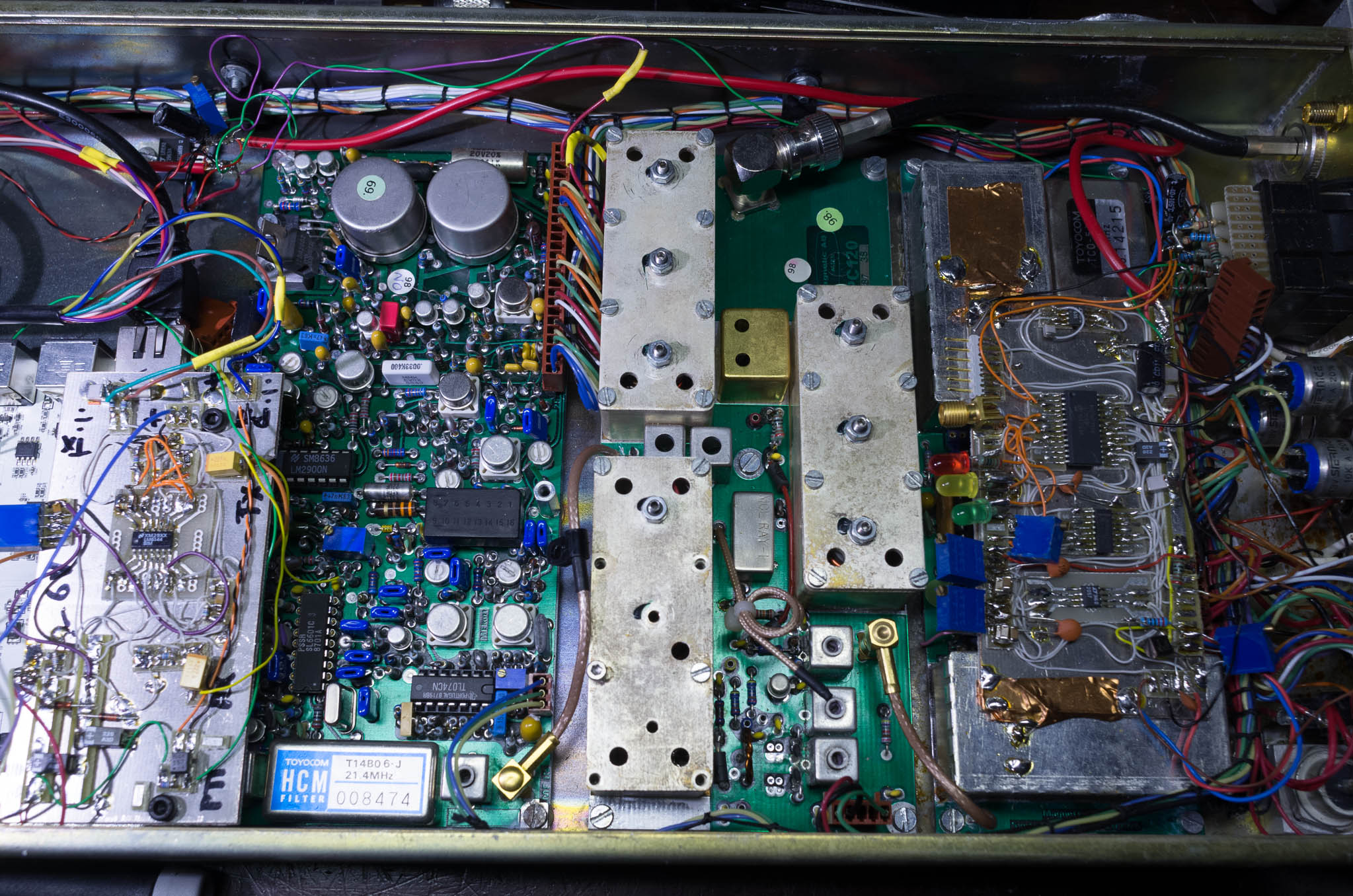
The receiver consists of a couple of boards:
- 1st converter
- Local Oscillator
- 2nd converter + discriminator and power
- Remote control board
- Some kind of other board
- Various front panel components + wiring harness
The boards basically follow a block diagram of a receiver with fairly standard interconnects, which made understanding its operation pretty easy.
The original sensitivity specification for the receiver was the following:
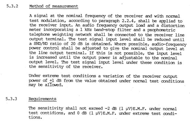
This was to be done with a signal 10 MHz away at 80 dBµV applied to the input, simulating an active transmitter system. Note that the sensitivity is for 20 dB S/N at –110 dBm, while most amateur radios use 12 dB S⁄N. The difference in effective sensitivity is e.g. –108 dBm for 20 dB SINAD and –120 dBm for 12 dB. The squelch opening level was also to be set to this –2 dBµV level, with 2dB hysteresis.
In practice the sensitivity of the system is largely limited by the attenuation and stop band of the first band pass section and first preamp. Achieving better performance than this with the requirement for very strong interfering signals is still challenging.
Due to the system design, adjacent channel rejection was also an important characteristic, with a requirement being minimum 75 dB rejection of adjacent channels.
1st Converter
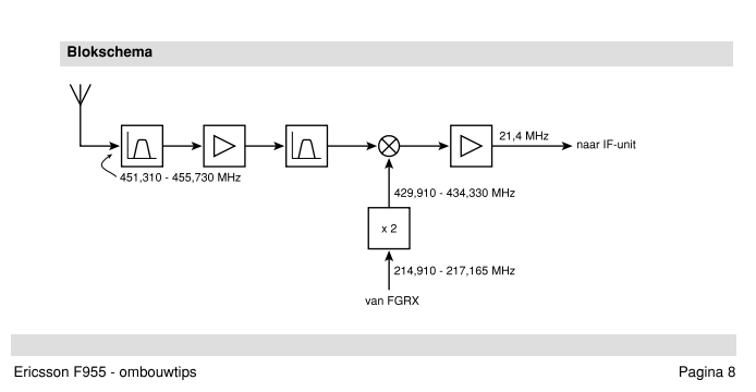
The 1st converter consists of helical band pass filters which can be tuned, a preamp, a second filter pack, a MCL RAY-1 mixer, and the IF output. The LO input is 10 dBm nominal and in this design seems to be multiplied by two on this board (block diagram for the F955 version shows only one doubler but this version has two of them in series).
I decided to replace the original preamp with a PSA4-5043+ mounted as a little sub-board on the bottom layer. This improved the performance a fair bit, though I did have to re-tune the filters after the replacement.
The coils inside the filters had to be extended about ¼ turn to let me tune them; I know some other modifiers simply added a new tapped hole next to the original tuning screws to offset them that way.
I don’t know what the point is in using set-screws for tuning here; the only difference compared to standard socket head screws is that the set screw uses a less common 1.5mm hex key and if you screw it down too far the set screw falls into the chamber.
One nice thing about DIN912 style screws is that the head diameter is the same as the nominal size of the nut of the same size so you can get a ring spanner over the head for tightening the nut in an application like this.
The board runs off a single 8 V supply. I believe the other pins may be an LO power detector, but I haven’t looked into this yet.
The original design included a large number of power measurement and similar test points to aid in troubleshooting. Most likely an automatic or semi-automatic assembly tester was used to simplify testing.
There’s no test point for tuning, but one way of tuning this circuitry is with a noise source + marker generator on the input, the 21.4 MHz IF is not filtered on this board so the full bandwidth can be tuned that way. Another way is to use an RF probe on the mixer input with a tracking generator on the input. Frequency range after retuning is approx. 432-436 MHz.
With a tracking generator and a mixer it would be possible to mix the tracking output with the same frequency as the receiver LO to move the tracking output to the nominal input frequency.
The doublers and LO BPF can can be tuned for maximum signal output, but as long as the LO is sufficiently strong there are diminishing returns wrt. how finely these need to be tuned. I recommend lubing the slug tuned transformers in the corner with PTFE spray before any tuning is attempted since they tend to crack otherwise.
I modified my converter by replacing the first LNA with a PSA4-5403+ board cut out of single sided PCB stock and wired to the appropriate filters, a 7805 regulator can easily be installed on the bottom layer as well. Keep in mind the bottom layer height clearance is only about 5 mm in this chassis so keep components low. I don’t know if this improved anything, but the filters had to be retuned after doing this.
Local Oscillator
The LO generates 6.25 kHz spaced frequencies which are multiplied up by 4 in the 1st converter board and used as a low side LO for the mixer with a 21.4 MHz IF.
The Dutch F955 version is fairly different since channel spacings were different which required a lot of additional circuitry. This version is fairly simple.
A 4 MHz reference is used instead of 4.225 MHz. A fixed 104 MHz reference is made using a multiplier off the 4 MHz. The VCO is mixed with this signal and amplified and fed into the PLL IC which is made by Harris. Control input to the PLL was 3 BCD digits that were summed with a binary input that would typically be fixed. This type of interface is ideally suited for connection to BCD switches.
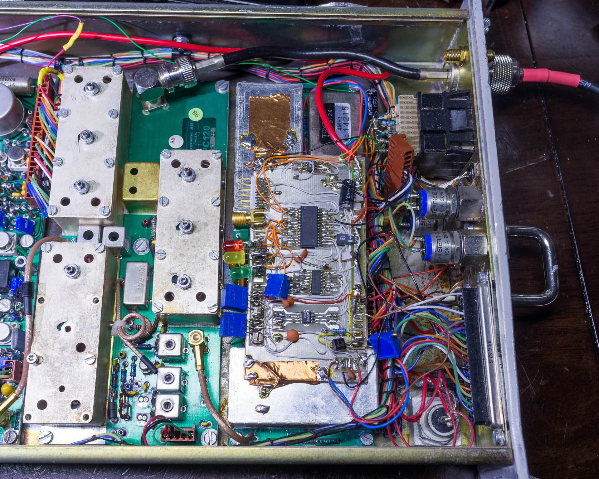
I broke the PLL IC in my unit when I powered it off a wall wart supply with no grounding and touched the grounded soldering iron to a pin, basically an EOS failure. As such I had to hack up a board with a new PLL that sits on top of the original circuitry, which is shown in the picture below.
The rest of the circuitry was maintained.
To get the synth working you might need to consider the wiring of the BCD switch; the switch goes all the way back to the remote control board since this board can remotely override the channel selection. It’s not too hard to match colours to get the BCD switch wired into the PLL directly if you want to remove the remote board. I have no info on how that board works and never made any attempt to reverse engineer it.
The original LO ran at around 106-108 MHz, the new frequency range is 102.65-103.65 MHz. Because of the mixer at 104 MHz that changed the sideband and effectively the VCO tuning polarity which is worth noting if you intend to re-tune this. The PLL polarity can be set by changing one of the pins on the PLL IC.
Adding some capacitors to ground on the bottom layer was enough to re-tune the VCO to the lower frequency. Since the control IC is socketed it’s not too tricky to remove it and manually tune the VCO.
To re-tune the synth for a different channel range all that is needed is to change the binary digit inputs to give the correct N divider value at the lowest channel number you need. Keep in mind the channel raster is 6.25 kHz at the PLL since the LO is later multiplied by 4.
Example:
Assume lowest frequency of interest: 432.000 MHz
LO Frequency = 432 – 21.4 (known IF frequency) = 410.6
VCO frequency = LO frequency⁄4 = 102.650 MHz
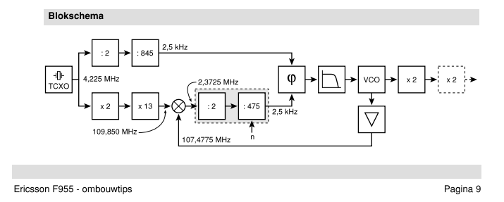
Here’s a complication: we have a mixer in the feedback path, see block diagram from Ericsson below
The fixed stable oscillator is 26x reference voltage (multiply by 2 then 11 in the can to the upper left), 104 MHz
PLL input frequency is 104 – 102.650 = 1.350 MHz
Let’s check our other end to make sure we don’t hit the mixer:
LO_1 = 436 – 21.4 ⁄ 4 = 103.65
PLL frequency = 104-103.65 = 350 kHz
We know the reference frequency is divided to 6.25 kHz (infer from system design, or power up and measure frequency at lock detect/PFD output)
N_0 -> 1.350 MHz ⁄ 6.25 kHz = 216
Other end:
N_1 -> 0.350 MHz ⁄ 6.25 kHz = 56
Whoops, since we moved from the higher sideband to the lower sideband of the mixer, our channel selection is backwards.
Since the binary N value is summed with the BCD value then either you can hope the PLL has a subtract mode, or live with the channels going the wrong way and program the binary N to 56.
I suggest making a spreadsheet to keep track of the channel -> frequency correlation if you go this route. No correction is really needed for the loop filters since the gain is likely to be about the same.
The Dutch version didn’t have this problem since their fixed oscillator was set to a higher value, and their LOs were all on the lower sideband to begin with.
Also note that almost the same layout is used in the transmitter except there’s a second set of varactors on the PLL.
The Toyocom 4 MHz VCXO is worth salvaging even if the board is scrapped.
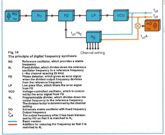
Ericsson Review also had a block diagram in their NMT 450 launch article showing a very similar design to the production version. There are advantages to downmixing the frequency instead of pure division since the effective N divider is lower, it also allows the use of slower processes for the digital dividers and PFD.
Mixers suitable for this application are fairly easy to implement using discrete RF transistors, while 100 MHz capable CMOS processes were pretty far away in 1980. Because of this the technique was fairly common in the 1980s.
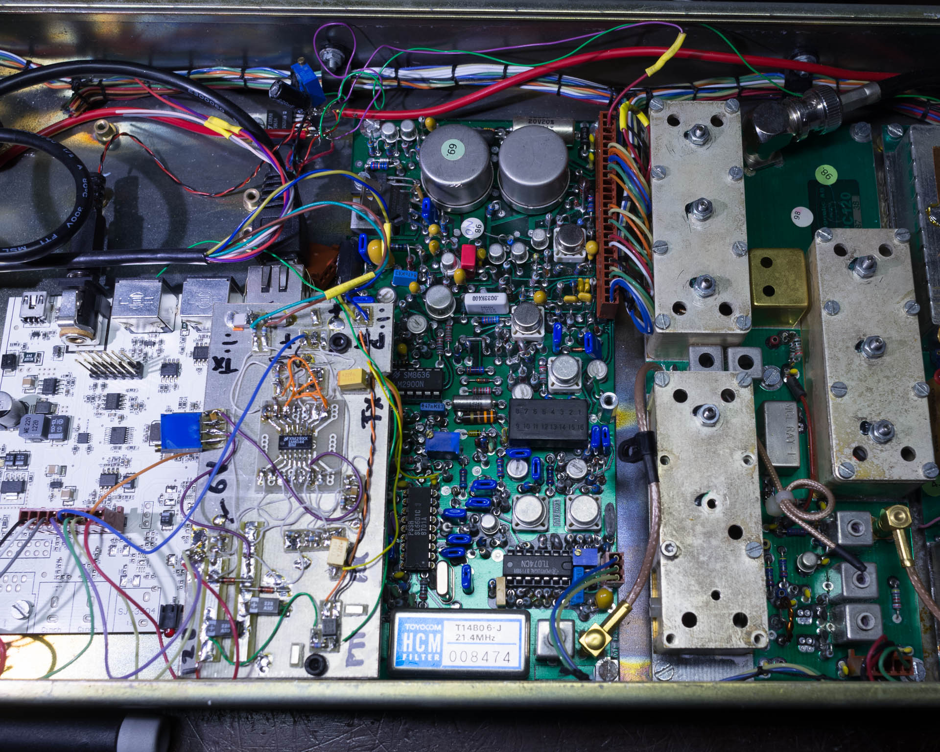
2nd Converter, Discriminator
The second converter has a Toyocom HCM filter with matching components, this is an absolutely fantastic filter and well worth the effort to desolder even if you are throwing out the board. Ericsson also used this type of filter in their mobile units.
It is likely this grade of filter was chosen almost entirely due to the strict adjacent channel rejection requirements.
The metal cans near the top are shielded audio transformers, bandwidth is quite good (suitable for general audio use) and these should also be recovered before the board is discarded.
There’s no schematic available for this board (dutch version is somewhat different), but the SL6601 VCO based discriminator is used for detection at quite a low 2nd IF due to the extremely good filter. I tapped the discriminator output directly and made a little board with AF filtering for my use with D-Star. A DV-RPTR board can be seem on the left.
A lot of the circuitry on the board is squelch circuitry and band pass filters for the two AF outputs from the receiver. I believe the two outputs are for data and voice.
Due to the filtering applied, these signals are useless for data modes (other than perhaps APRS).