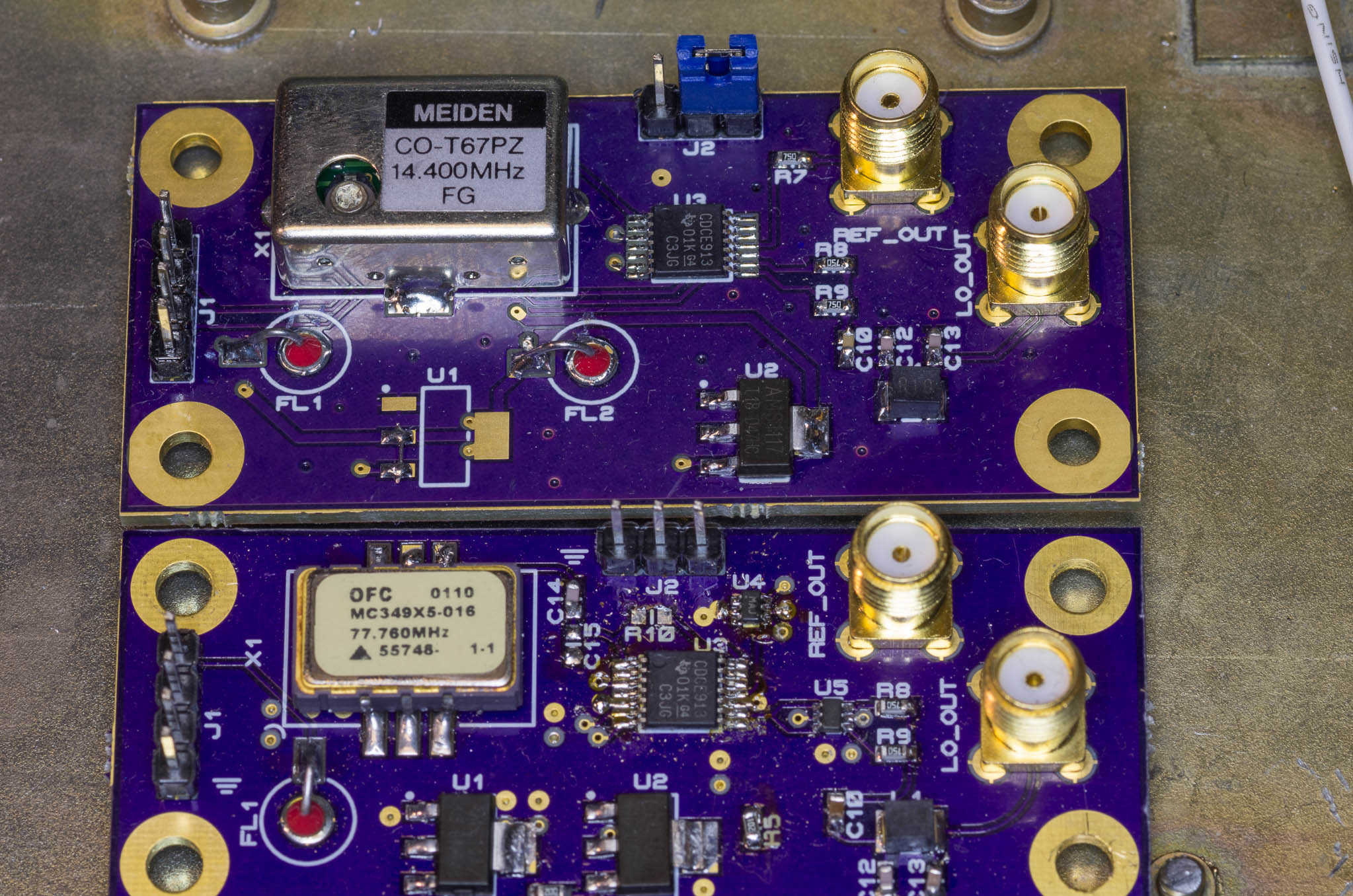
MC349X5-016 77.76 MHz VCXO
This page has some info on the MC349 VCXO, that has been available on eBay in large quantities at low cost.
The VCXO seems to be a Corning design, but now owned by Vectron. The data sheet for the Vectron VX-500 series includes a notice that previous models include the MC349.
The frequency may seem strange, but it's a sub-multiple of 622.080 MHz which is a common clock frequency for high speed communication systems.
It's likely it was used for this purpose in an early high speed telecom application. I've used this part in several applications, and intend to use it further as it has a lot of potential for FM systems:
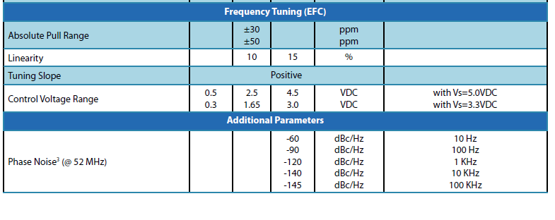
Basic Specs (probably)
These are some quick specs from the data sheet; if you can't find the VX-500 data sheet, email me and I'll send it over or host it here.
This variant seems to be a 5 V nominal VCXO; it operates just fine on 3.3 V however.
The output appears to be ACMOS, with likely current capacity of 40 mA symmetric. That's a pretty powerful output driver. Fundamental power at 5 V is around +10 dBm into 50 Ω.
Frequency accuracy seems to be in the ±2 ppm range, not terrible.
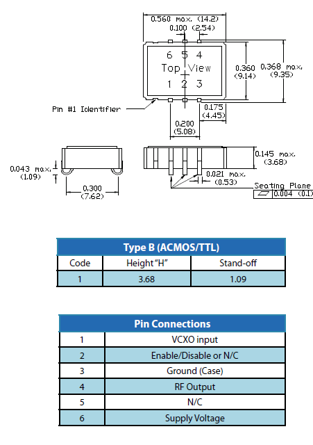
This variant has an enable input and a VCXO input; the enable must be high to operate. Tuning range seems to be 0-VCC or so. Pin 5 is N/C (used for the complementary output for PECL variants).
I can't decode the other parameters since no key is provided for the MC349 part number series, only the newer VX-500 series.
VCXO transfer characteristics
I've put one of these in a test board and tested it both for linearity and FM bandwidth when used as a modulator:
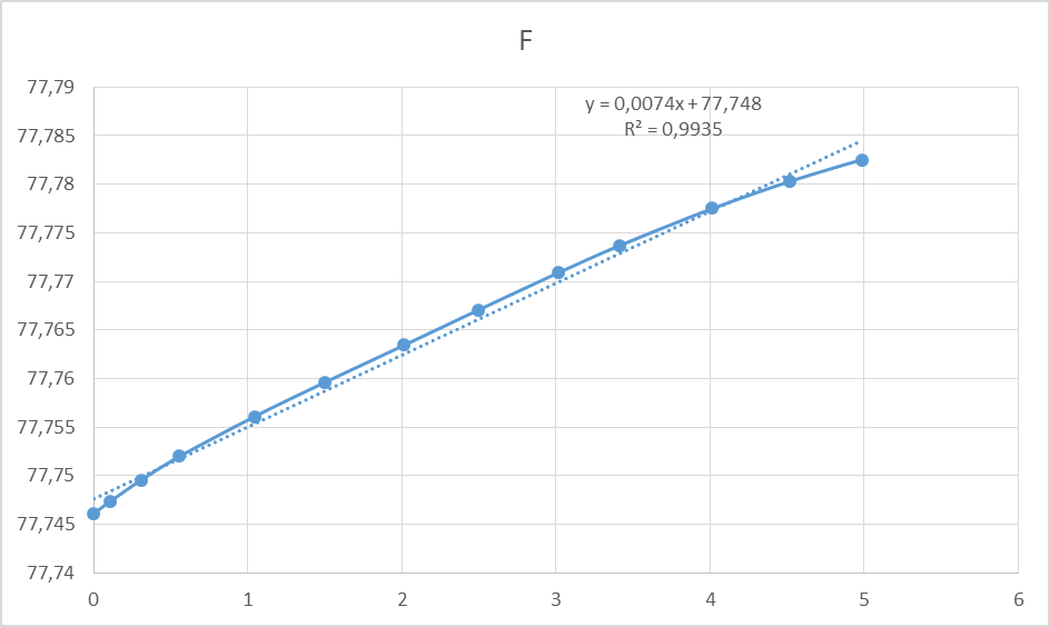
The linearity is quite good. It can also be seen that a 77.75 MHz frequency can be used without major problems, though it can't be reasonably modulated around this frequency. The good linearity makes it well suited for phase locking if needed.
In addition, I've added a sub-plot showing the optimal DC offset to use when operating it as a modulator:
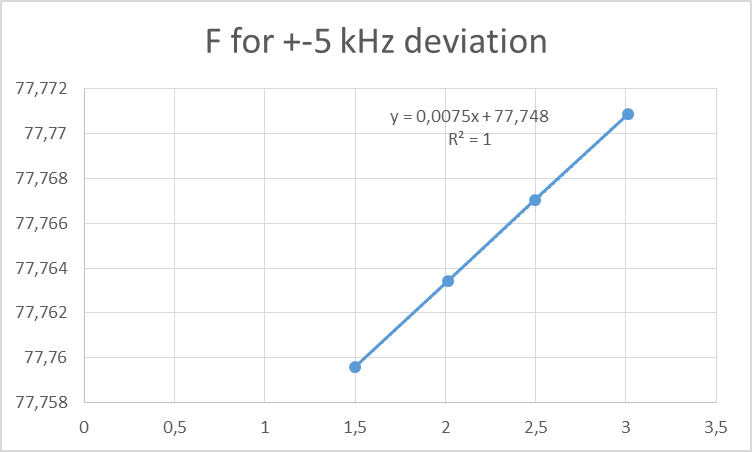
It can be seen that a highly linear FM modulator can be implemented using this VCXO, despite the quite poor specification the actual performance seems excellent.
A nominal 77.765 MHz frequency was the optimal bias point for this modulator.
While I don't have numbers, I've tested the same board using my Wavetek 4015 and distortion is excellent, and modulator bandwidth is DC-5 kHz within 0.1 dB.
Updated:
I did some measurements on a de-capped VCXO, the input R-C filter on the varicap is 100 kΩ/470 pF. This corresponds to a upper frequency of around 3 kHz, it's possible to extend the response if you have enough voltage by using an op-amp high pass filter.
Update again:
Driving the VC pin with fast slew rates can cause the oscillator to stop momentarily, this makes it much less suitable for FM demodulation.
Inside
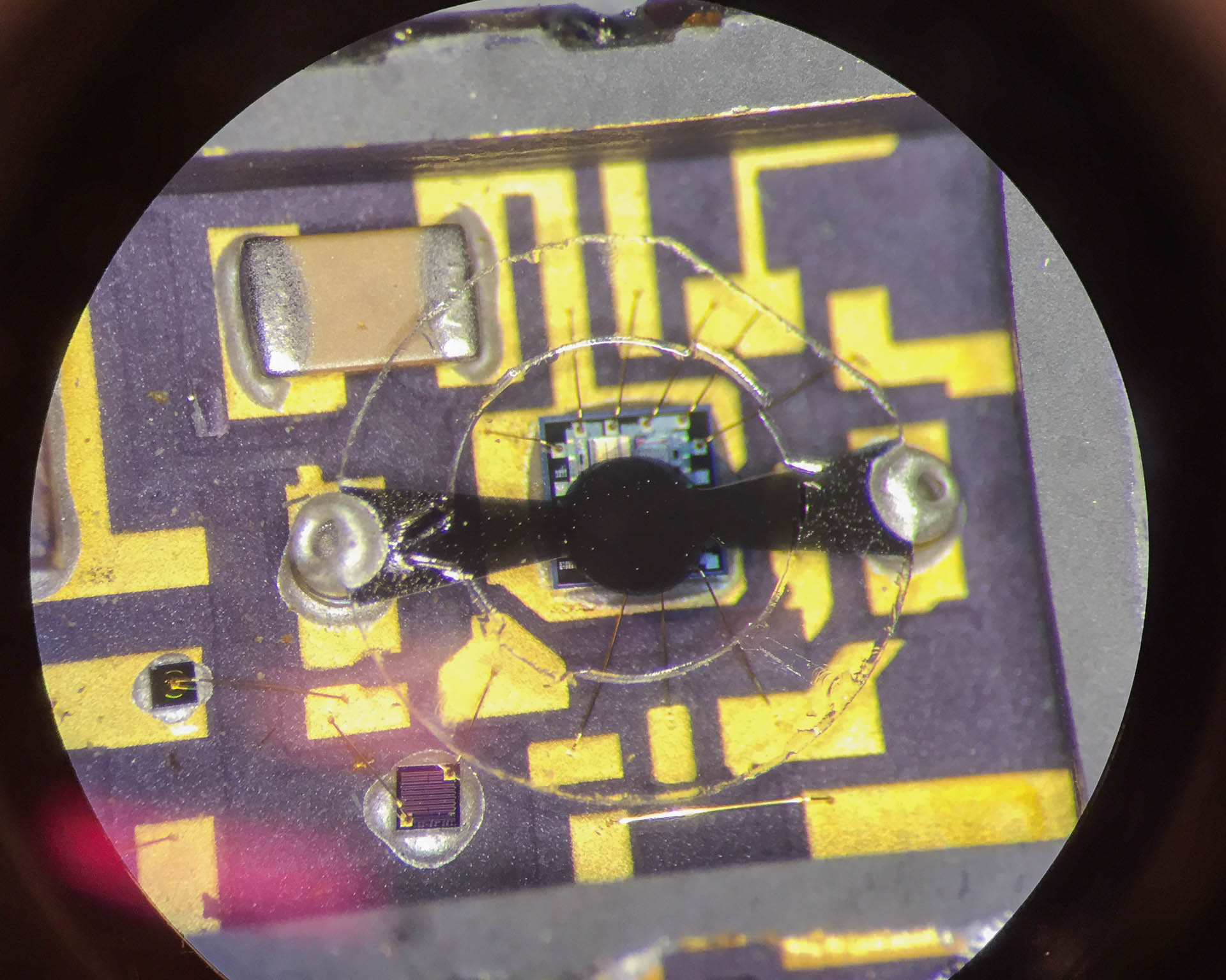
It's widely known that it's what's on the inside that counts, so I popped the lid off one of these:
The crystal is suspended above the main die containing a decent amount of stuff; I didn't have a microscope adequate to get a die shot.
A resistor can be seen in the lower left of center, and what might be the varicap diode to the left center.
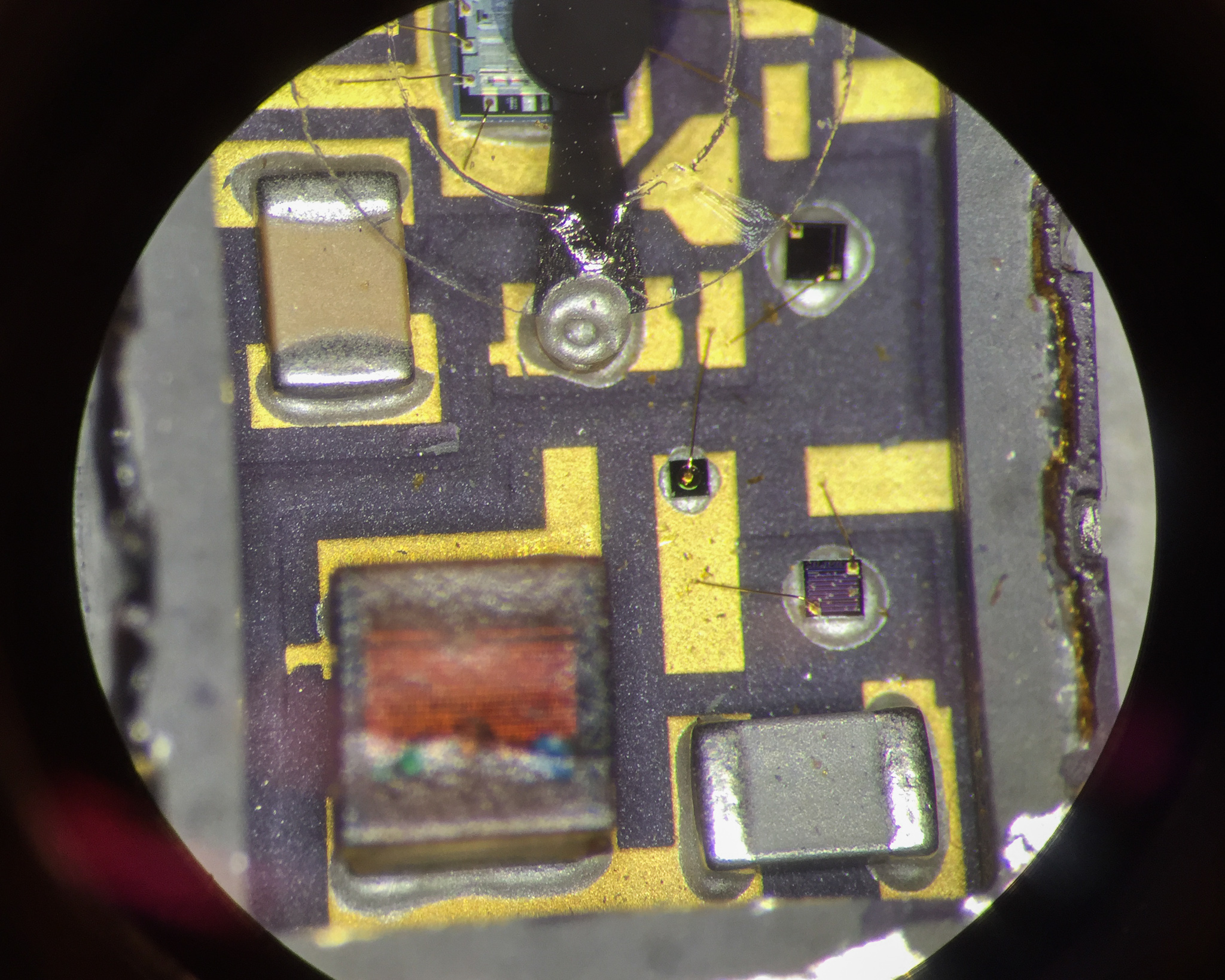
If memory serves the inductor is in series with the power supply, while the resistor just to the right below center is in series with the VCXO input. This is a typical circuit arrangement for an oscillator tuning input.
From the looks of it, this hybrid ceramic module was not exactly cheap when new; a current VX-500 goes for around €8 a piece in 1k quantities.