Military Handset Interface for Mobile Radios

Continuing even further along the military radio thread, I previously discussed military handsets here.
In this post I will show how I built a basic interface-box/intercom for interfacing a generic military handset to mobile radios such as the Motorola GM360 and the Hytera MD785.
Obviously I expect this design will work with many other radio types, but those were the ones I wanted to use.
Our goals here are:
- Amplify the microphone signal to the ~80 mV RMS level that these radios use, gain should be adjustable
- Amplify/attenuate the handset-audio output as required for a comfortable volume and balance with the built in speaker
- Driver suitable for 1 kΩ dynamic speakers
- Adjustable microphone monitoring in the handset speaker, to make it easy to determine audio quality and for improved comfort
Note that this design is not well suited to typical headsets which often use lower impedance speakers, you will need to add an external speaker driver in this case (really just a high current voltage-buffer is required).
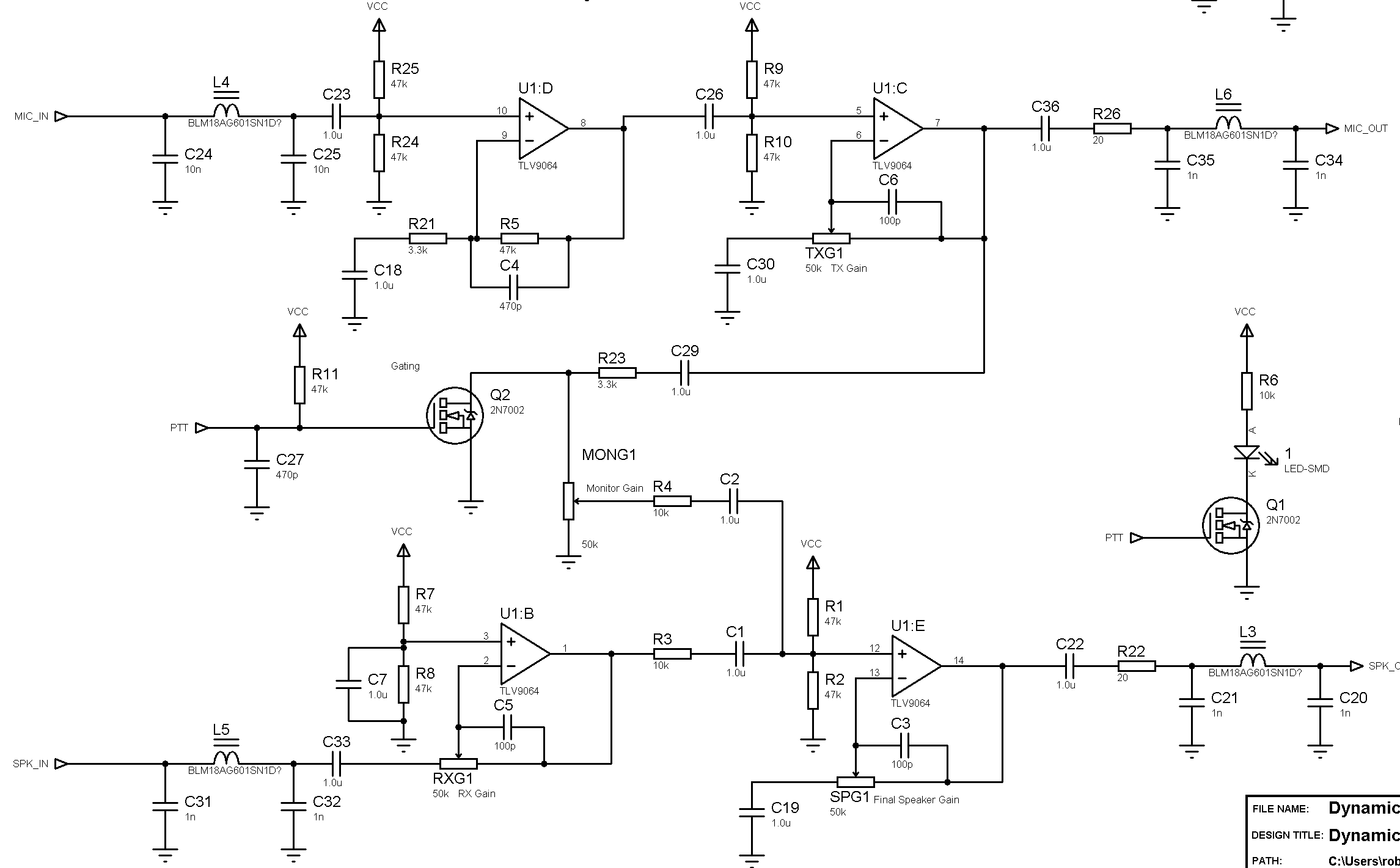
Skipping right to it, here's the solution I came up with:

The amplifier is a TLV9064 (TSSOP-14), this is quad opamp with very similar but slightly better performance than the TLV316 used previously. The main reason for choosing it is that we can relax the quiescent current requirement, and that I already had this opamp unlike the TLV4316 I would have otherwise had to buy.

As shown the design is suitable for direct connection to the microphone, with a noise figure around 20 dB or so. Since I wanted optimal performance I decided to use a 150:47k (i.e. 600CT:47k) audio transformer on the input, and as such the value of C24,25 was reduced from 10 nF to 100 pF. Further, R21 is DNM, and R5 is replaced with a 0 Ω resistor to make the input stage a high impedance voltage follower instead of a gain stage. This gives a noise figure in the 1-2 dB range, approximately 20 dB better than required.
A 600CT:47 kΩ transformer followed by a CMOS/JFET buffer is the optimal way to amplify a 150 Ω microphone since it provides near perfect noise performance. However, this solution is relatively expensive ($10-20 per transformer) and bulky. A standard audio CMOS opamp (5-10 nV⁄√Hz) will give sufficient SNR for radio use.
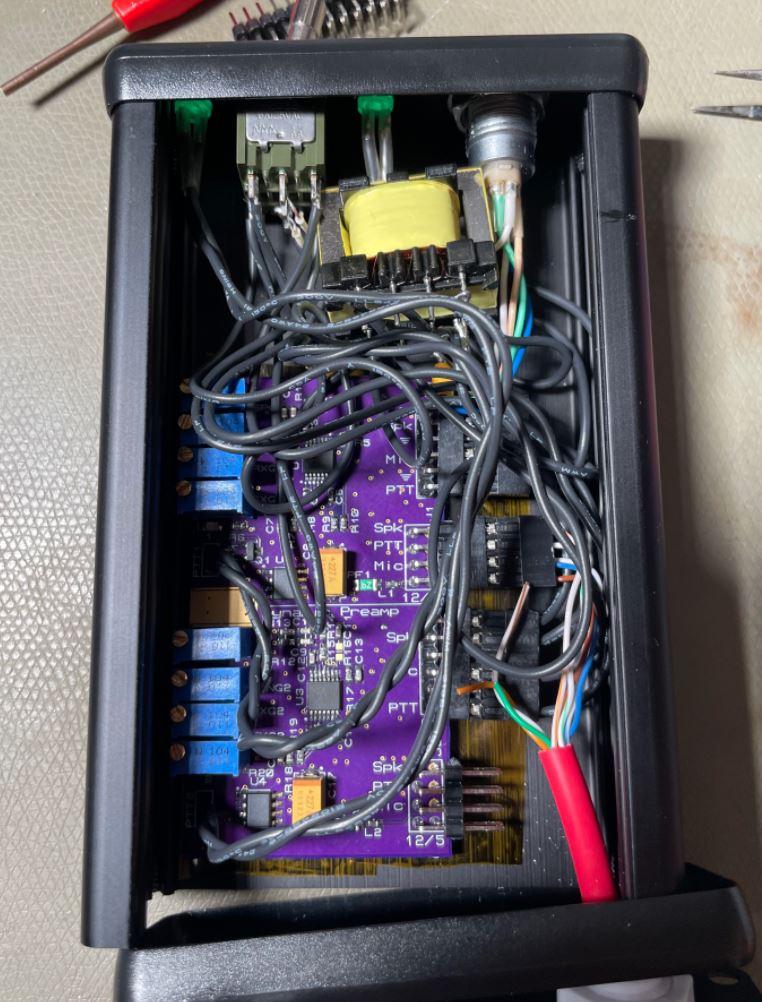
Electrostatic shielding is recommended, make sure to ground the chassis to the circuitry. I used a countersink rivet + a solder lug.
U1:D is the same basic amplifier as the previous design, but it's followed by U1:C which has a multi-turn potentiometer for feedback to adjust the gain from 1 to too much over around 20 turns.
For the handset audio (most professional radios have this output, with the volume linked to the speaker), we use an inverting circuit with adjustable gain, inverting since we may want a gain below 1⨉ here.
Between the handset audio preamp and the output-driver, we have a summing network that feeds the amplified microphone signal through a monitor-gain pot, and combines it with the receive handset audio. This allows the level of microphone monitoring to be adjusted, and the combination of RXG, MONG, and SPG pots can be set up to give a suitable level relative to the radio speaker + a suitable monitor level, though it is a bit fiddly to adjust initially.
Q2 senses the state of the PTT line, and only enables the monitor audio when the PTT button is pressed; this is sensible for most handsets to reduce noise, but you could just remove Q2 to always monitor (e.g. for a headset, or a H-350 handset). There is also an on-board PTT-LED, and a header for an external one.
The design runs off 5 V internally, there is a 5 V input direct, and a 78L05 (SO-8) regulator that can take 8-15 V in if that's what the radio wants to give you. Operation at lower voltages is also possible down to ~2 V with the caveat that you may not have enough voltage to drive the handset speaker properly.
Unfortunately the inputs/outputs are single-ended, since most radios don't have balanced audio, so ground loops may be an issue.
The PCB layout fits into e.g. a Hammond 1455J1201 box, though the potentiometers on one side interferes slightly so I just installed it with an insulator and some double sided VHB tape.
The design actually contains two complete circuits, with a common ground plane. This was done since I want to interface two radios, but preferably not have to use two handsets (I have them, but they'd get tangled).
As such the intended use is to connect two radios, and then use a 3PDT toggle switch such as the NKK M2032LL1W01 (latching type) to switch the three signals from the handset. This allows fully independent level matching for each radio.
It also makes it possible to fit two handset plugs if desired. To do this, simply wire the additional handset plug to the secondary radio, with the switch set to primary you can then plug in the second handset without interference.
If you're a real badass you'll wire the same handset to both radios without the switch and always transmit on two frequencies. Double your contesting score with this one weird trick.
In my system I use a Lemo 1B 7 pin connector for these handsets (I use 7 pin socket connectors, and 6 or 7 pin pin connectors depending on what I have around; these will mate as long as the socket-side is 7 pin).
This is a non-standard pinout I decided on for my own use that is compatible with both half and full-duplex handsets, but you could wire in something like a U229 compatible plug and use a stock H-250 for example.
I will note that using these smaller circular plugs for interconnect is fairly common in real life since the U229 series is ridiculously big compared to a Lemo 1B. In practice the 1B series is not suitable for military use since it isn't even close to waterproof.