Modifying Icom IC-V200Ts for 12.5 kHz channels

I looked in to modifying the IC-V200T for use with modern repeaters with 2.5 kHz deviation.
Table of Contents
The V200T and H16T were primarily made in 5 kHz deviation variants, but there are provisions for making a 2.5 kHz variant (which I'll refer to as narrow) (UK models are likely to be narrow according to the documentation I have).
I won't cover the transmit deviation here since it's just a matter of following the adjustment spec and tuning for 2.5 instead of 5 kHz.
Receiver Differences
The receiver changes to use 2.5 kHz deviation are roughly:
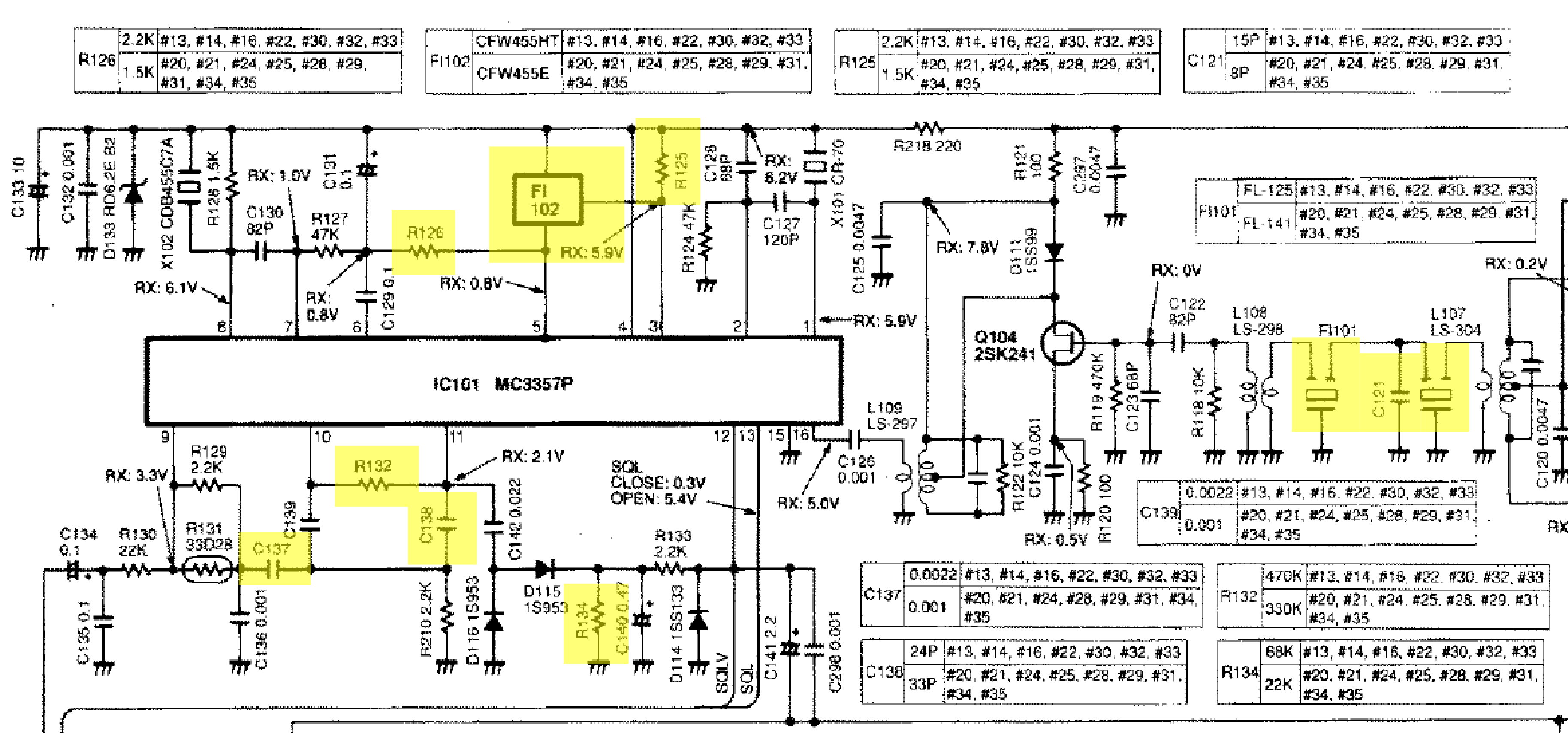
- New 1st IF filter (21.4 MHz crystal, 2 pcs) and different 1st IF coupling caps
- New 2nd IF filter (455 kHz ceramic) and associated matching resistor
- Coupling capacitors/resistors near the AF output
Parts List
Based on this we can set up a parts list:
- Icom FL-125
- See the H16T mod post since it's the same part.
- CFW455HT (455 kHz ceramic, ±3 kHz bandwidth)
- See the H16T mod post for information about where to get this.
- Resistors:
- R126 -> 2.2 kΩ
- R125 -> 2.2 kΩ
- R132 -> 470 kΩ
- R134 -> 68 kΩ
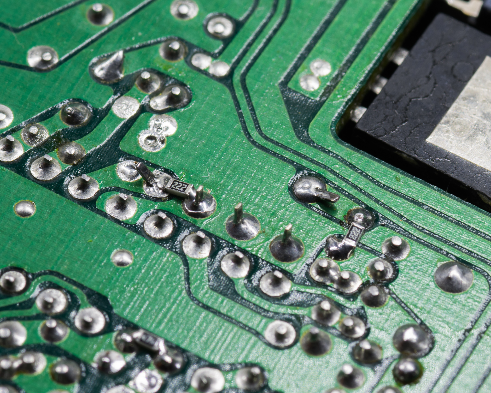
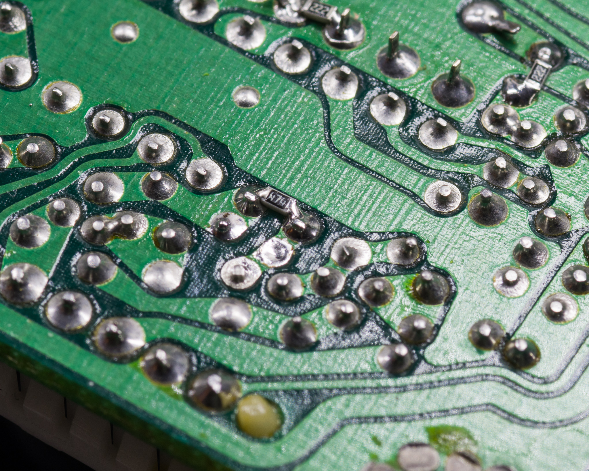
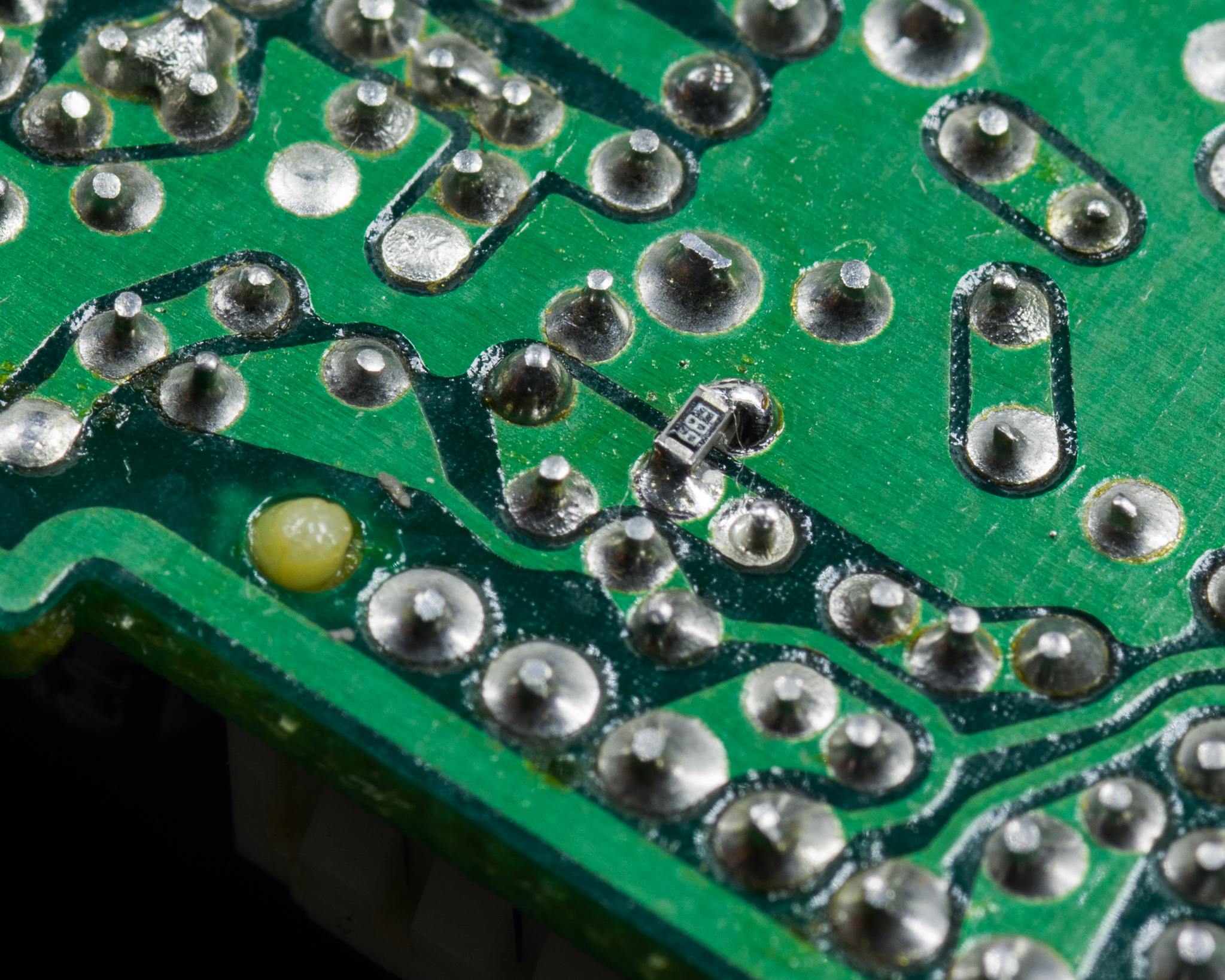
- Most of these are vertically mounted 1/8 W resistors, you can sneak in a 0603 between the pads if you want to use SMD
- Capacitors:
- C137 -> 2.2 nF (was 1 nF) (I used a 0805 1 nF for this)
- C138 -> 24 pF (was 33 pF)
- C121 -> 15 pF (if replacing the crystal filter)
- I used SMD caps since I have more of them than leaded disc caps
Note that the part numbers listed in the silk screen on my version of the PCB skipped the leading 1, so R125 is labelled R25 on the Main Unit PCA.
Implementation
This is pretty straight forward, the most annoying thing is dealing with the PA module thermal compound when removing the board. I used some 1 mm thick blue thermal mats I found on eBay when reassembling this since they perform adequately for jobs like this and are much easier to work with.
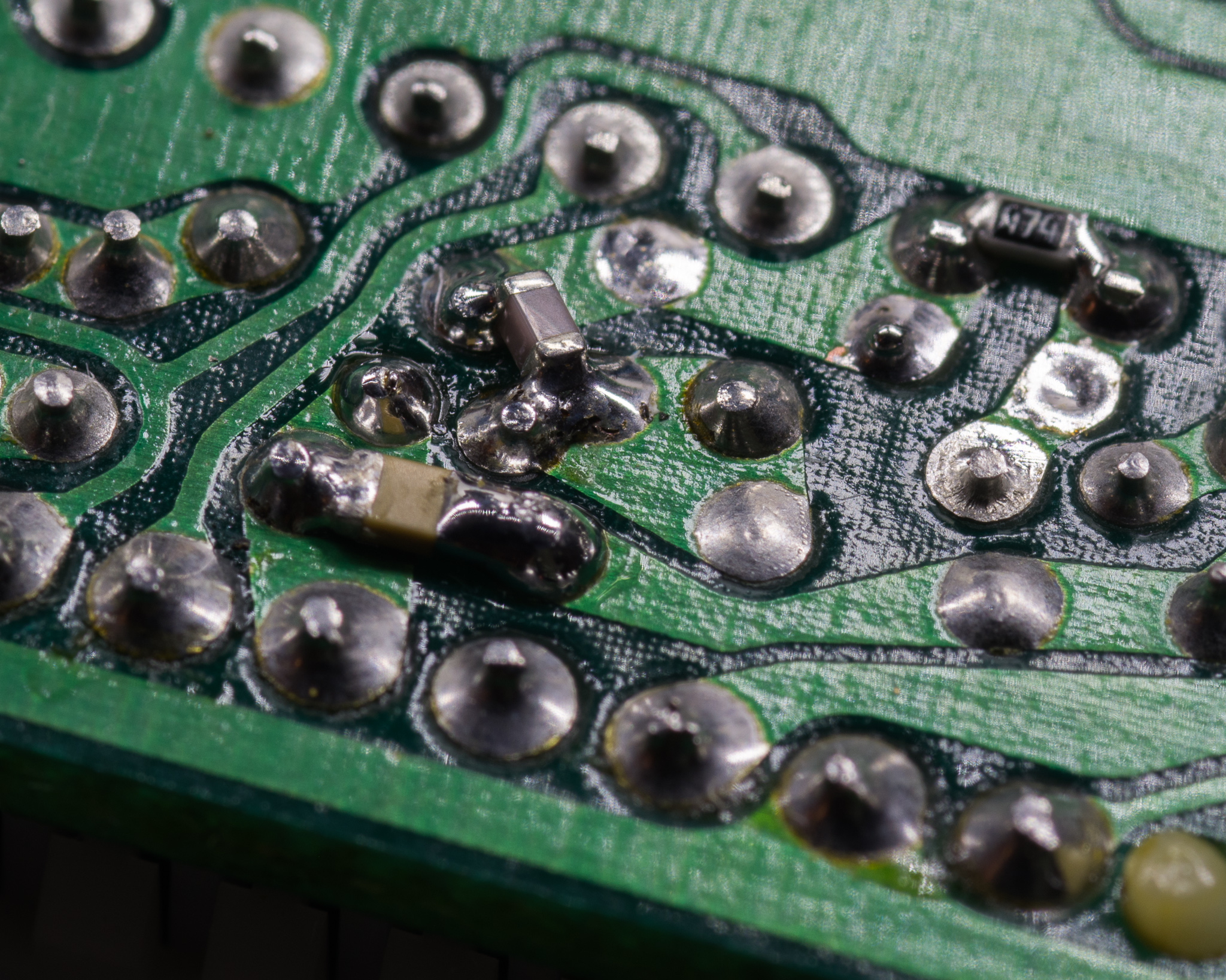
I took pictures of the components I added, with the exception of C137 I removed the original component first.
Performance, Adjustment
With the new filter receiving a 5 kHz modulated signal gives significant distortion compared to with the wider 2nd IF filter, showing that it's working.
Squelch adjustment is required after this mod, I adjusted for a slightly tighter squelch than required and ended with an open-threshold of around –119 dBm for 14 dB SINAD.
12 dB SINAD was at –121 dBm with the specified 1.75 kHz dev test signal.
You'll need to re-adjust the TX modulation if you haven't already done so.