Modifying the Icom IC-H16T for 12.5 kHz Channels

I looked in to modifying the IC-H16T for use with modern repeaters with 2.5 kHz deviation.
Table of Contents
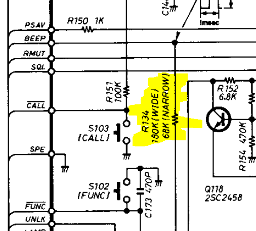
The V200T and H16T were primarily made in 5 kHz deviation variants, but there are provisions for making a 2.5 kHz variant (which I'll refer to as narrow) (UK models are likely to be narrow according to the documentation I have).
I won't cover the transmit deviation here since it's just a matter of following the adjustment spec and tuning for 2.5 instead of 5 kHz.
These modifications are largely the same for the IC-V200T but it's actually harder to mod the V200T since the relevant PCB is very tightly connected to the chassis.
Changes
The bare minimum mod is to re-tune for 2.5 kHz max deviation, but I recommend at least changing the 2nd IF filter.
Changing the 1st IF filter is left as an excercise for the reader, since I didn't have any crystal filters laying around.
Here's the recommended list of changes:
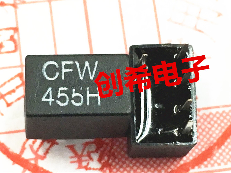
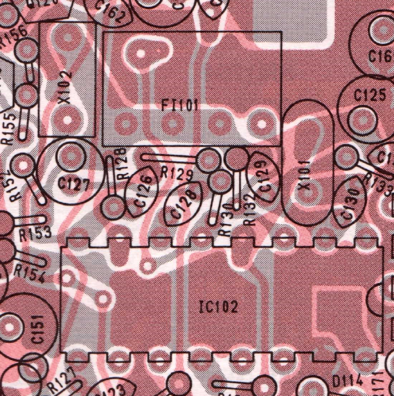
- FI101
- Was CFW455E, changed to LT455HTW (readily available on Aliexpress)
- Note, these are sold in two different pinouts; you need the kind with four pins in a row and the fifth on the opposite side. See picture below.
- R130 and R132 (impedance match for FL101)
- Was 1.5 kΩ, change to 2.2 kΩ
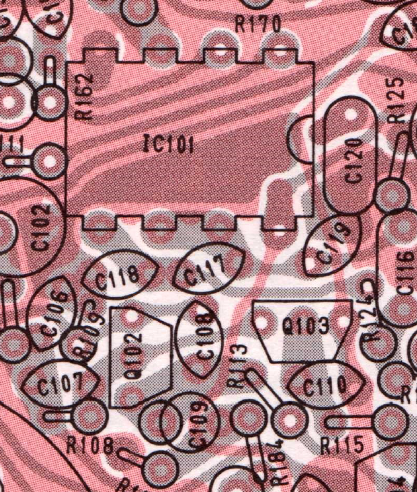
- R124
- Was 39 kΩ, change to 56 kΩ
- C118
- Was 100 pF, change to 120 pF
The last two values aren't strictly required since they just change the max deviation/TX low pass, you can still adjust the radio to 2.5 kHz without changing these.
If you want to go all in, you have to find an Icom FL-125, listed as "21M7B2". The only readily available commercial component these days is the "ECS-21K-7.5B" made by ECS Inc. and sold via Digi-Key. Note that you'll need two of them so ordering the matched set is recommended.
There are a couple of other differences between the wide and narrow version, I've tried to find all the important ones and list them here:
Reducing this resistor value increases the AF gain. Reducing the value of C169 might get you some more treble if desired as well.
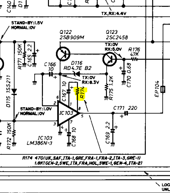
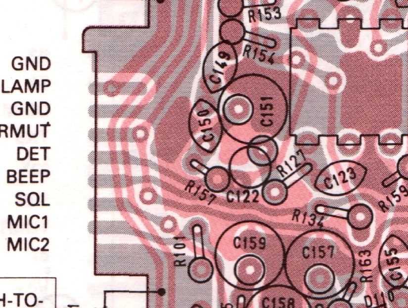
If the keypad beep is too loud, change R134:
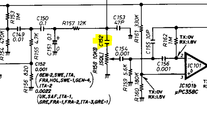
C152 is related to the squelch control circuitry (reducing the noise squelch high-pass). This compensates the squelch to match the new IF bandwidth and I recommend doing this.
Implementation
I chose to use 0603s for R130 and R132 since I had a reel of 2.2 kΩ's, so I included a picture of where I put them. If you were in a hurry you could just clip the leads off the old ones and leave them in there.
Here are the relevant foil drawings:

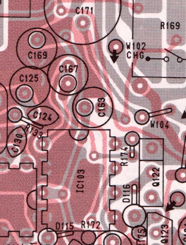
Tacking a 680-1200 ohm 0603 across R174 should be fine here.
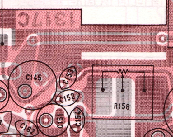
Just tack a SMD 1nF resistor on the bottom for C152.
Measurements, Adjustment
You may want to adjust the radio, definitely adjust the TX if you haven't already. Follow adjustment procedures for model #33.
I also did some testing on the old Stabilock, and got some approximate numbers:
12dB SINAD: -120 dBm
6 dB sensitivity: ±3 kHz
30 dB sensitivity: ±5 kHz
As is typical of the H16T sound, I also got a very sharp roll-off in the RX audio between 2 and 3 kHz.
Getting the right LT455
Check the picture to be sure you get the pinout shown below: