The NAGRAFAX — Fixing The Phasing Circuit
A followup to the previous NAGRAFAX article, this details how I fixed the automatic phasing circuitry, and has some detail pictures of the electronics boards.
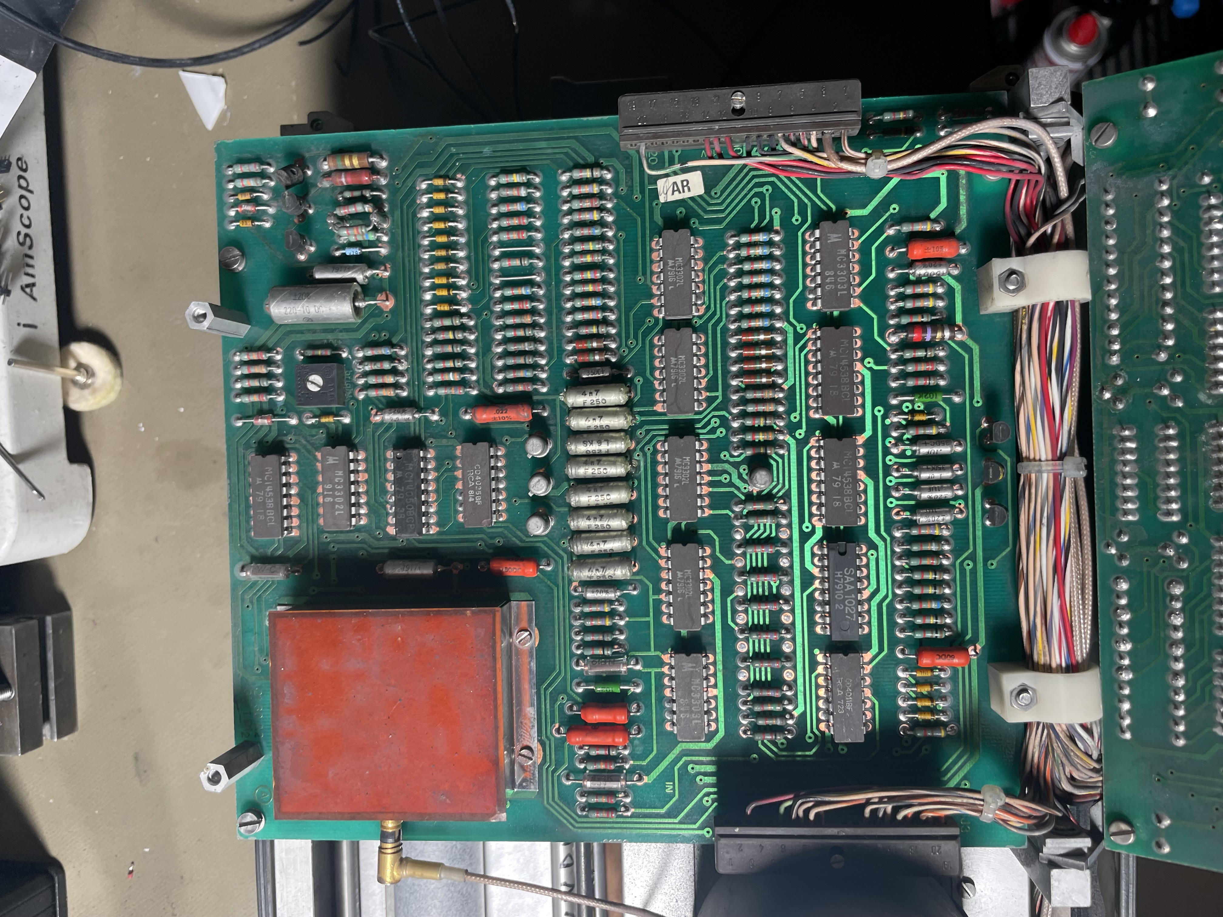
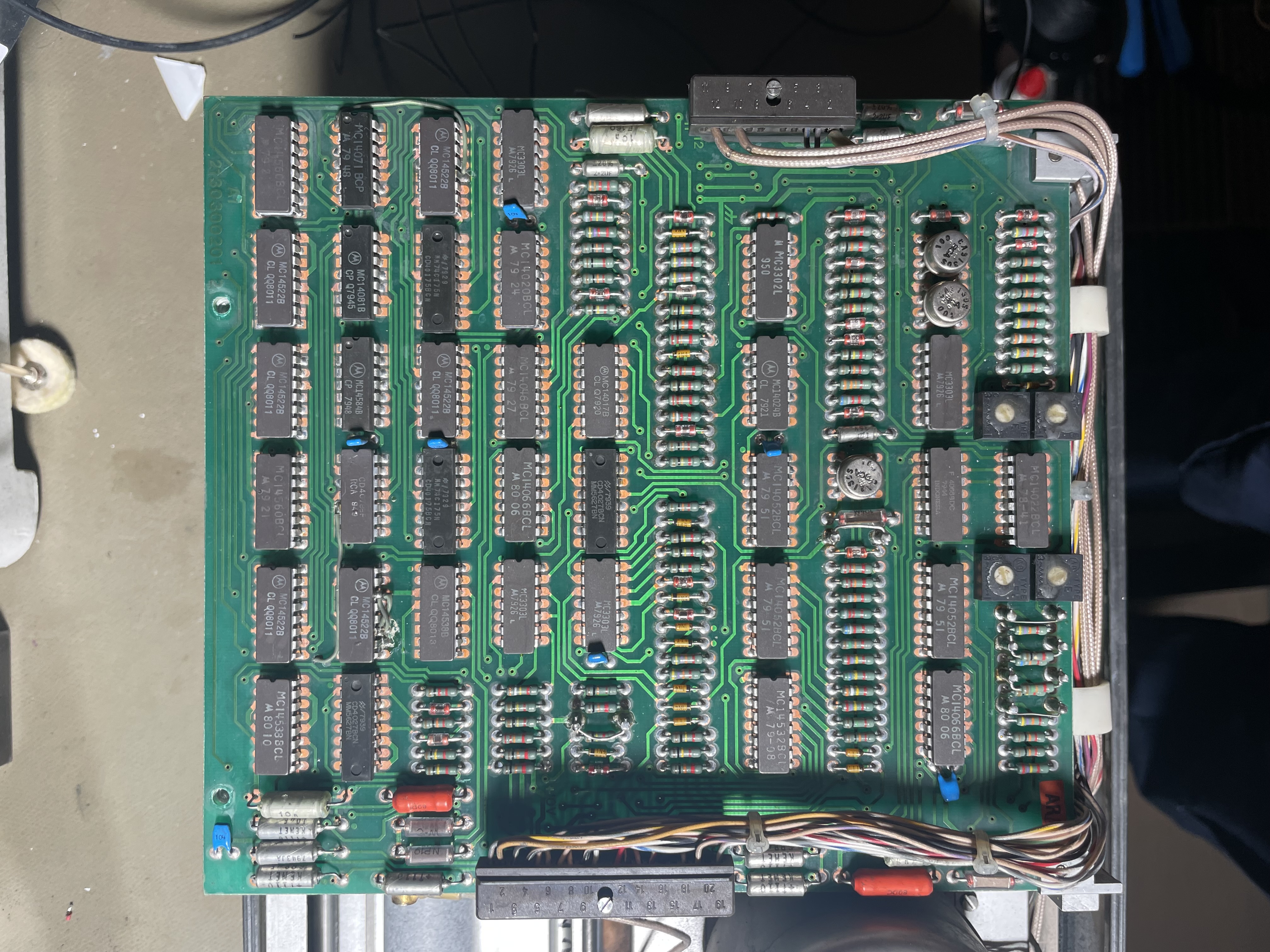
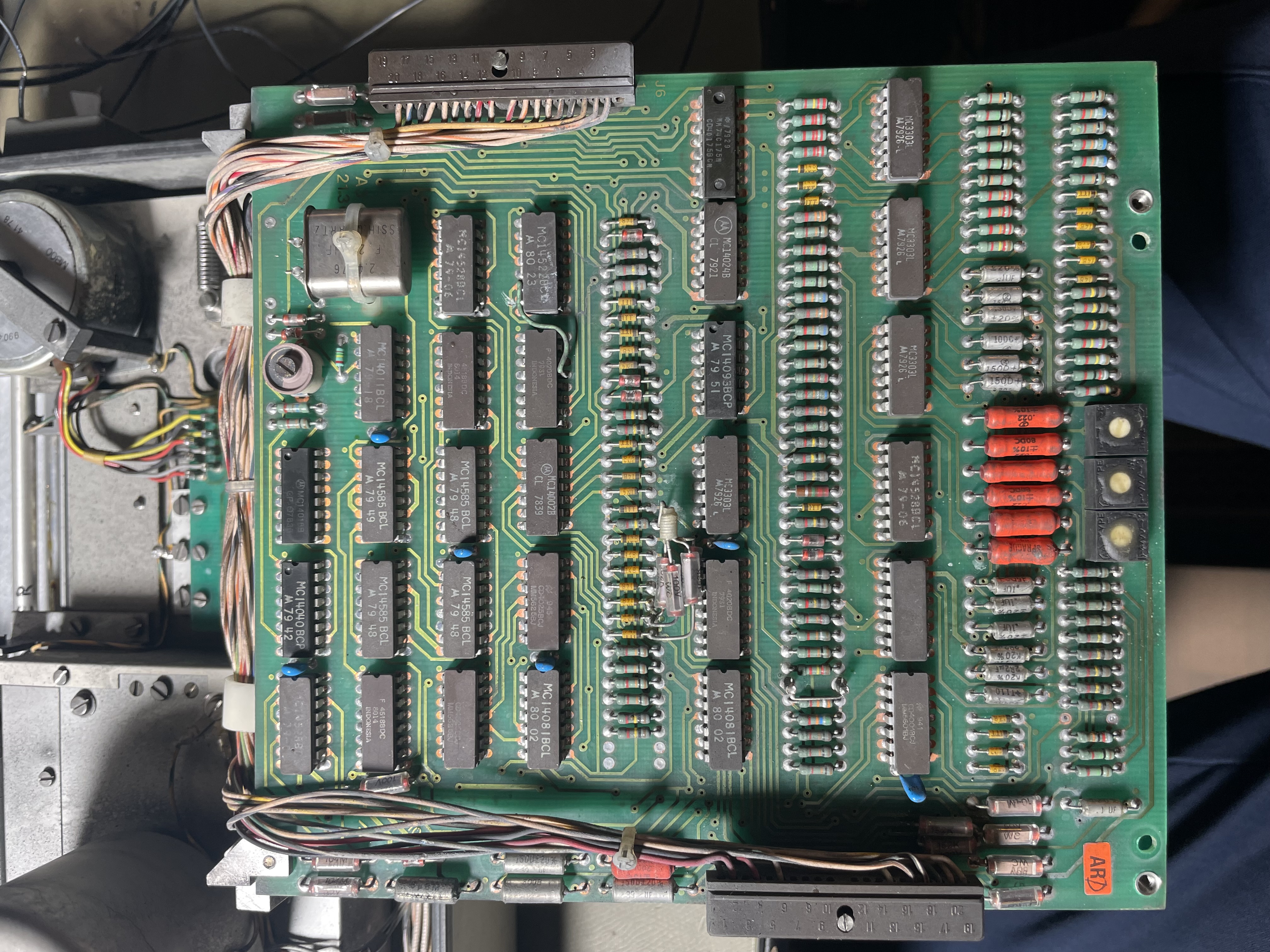
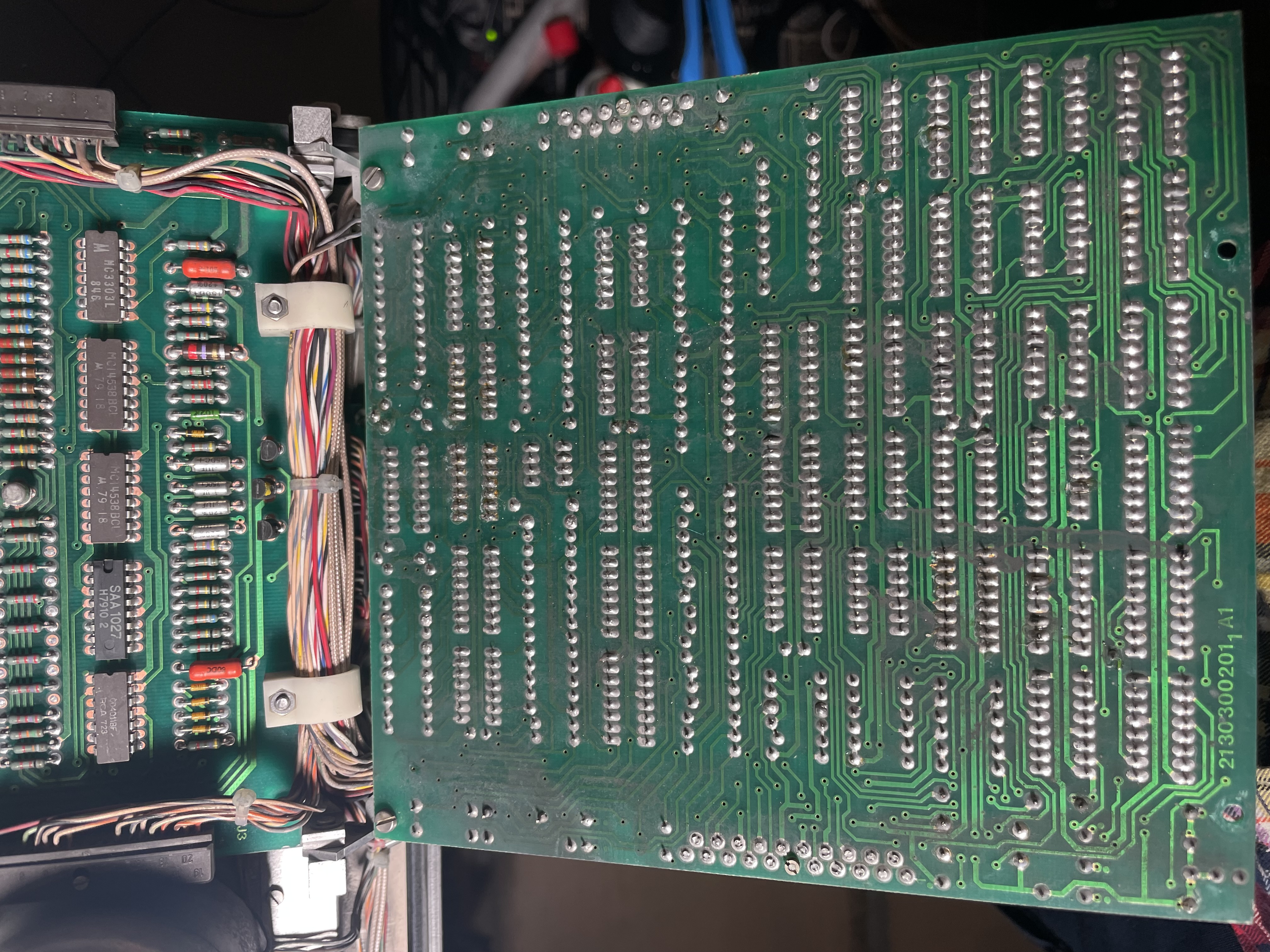
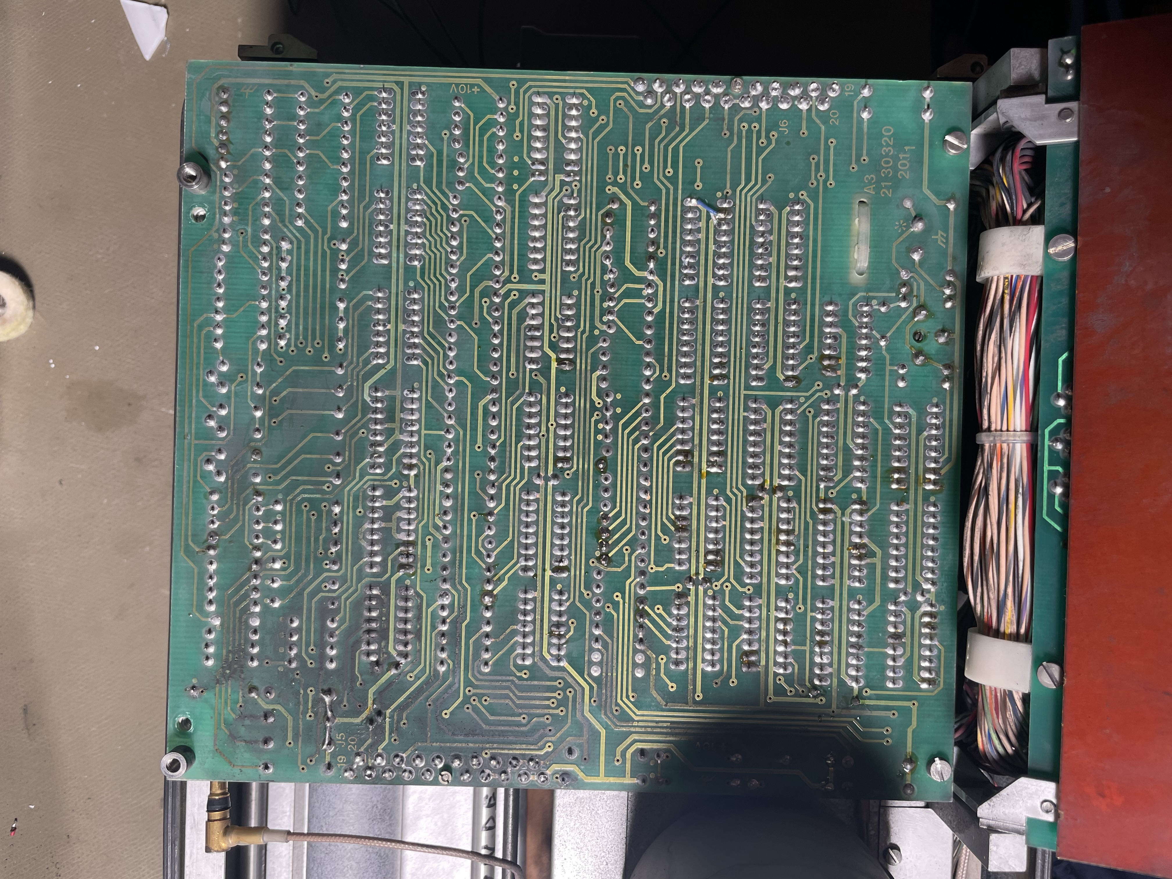
PCA Overview
The PCAs are hinged at various offsets, once a few sets of screws are undone all the cards can simply be rotated up to access the front and back. The only annoyance is the short cable going to the write head (the coax).
How The Phasing Circuitry Works
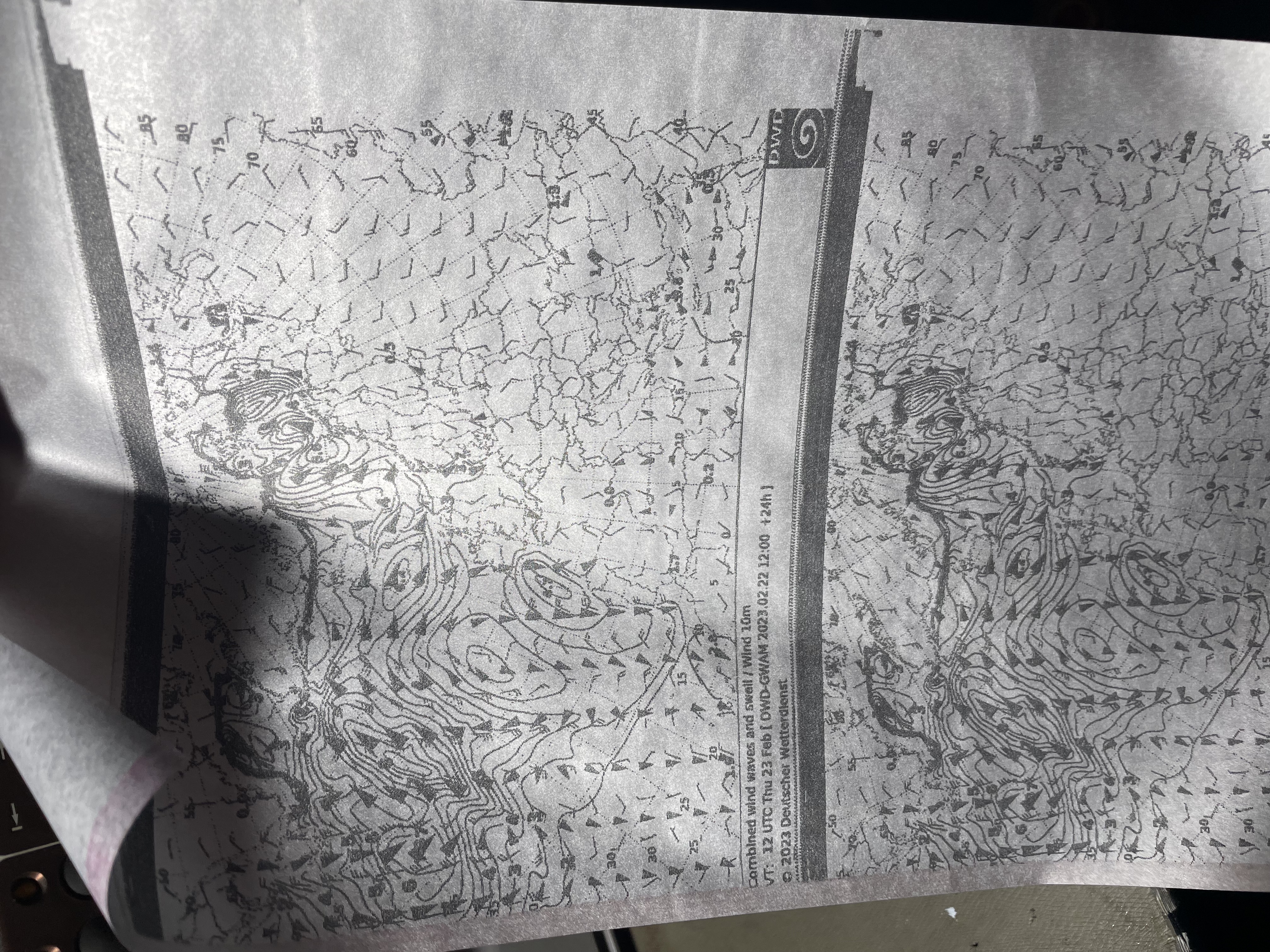
Below is an example of the defective phasing circuitry I received the fax with. The diagonal lines are the index pulse, and DIP switch 1 is on to make the fax print the entire phasing sequence. The diagonal lines is the fax trying to synchronise by speeding up the chain drive slightly.
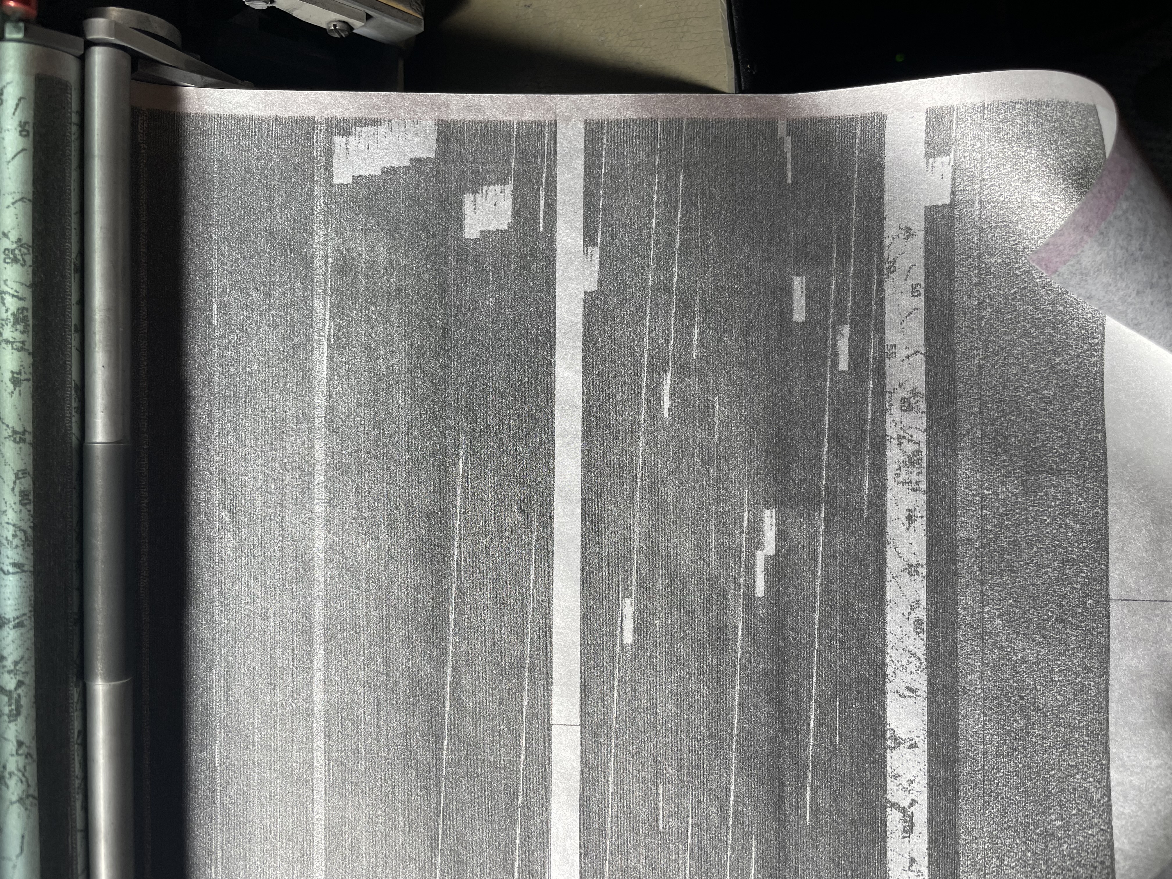
Clearly not working right, the phase is random at the end, and it only goes in one direction, even passing the correct phase without doing anything.
The system took some head scratching to understand, I drew a block diagram of approximately how it operates to aid in understanding it.

- Video Sync is the video synchronisation pulse, the period of this pulse is measured in the phase accumulator. It controls a ripple counter U21 that clocks a 7 bit counter (2⨉4522) acting as the phase accumulator
- This is clocked by the chain drive direct tachometer signal, this is fairly high speed signal
- I think using the chain drive speed signal instead of the crystal speed affects the loop dynamics, probably it results in a stable loop gain independent of the LPM count
- The phase accumulator is sampled (latched) once per head sync pulse
- If in phasing mode, the 2-line head pulse counter triggers a JK flip flop that modifies certain bits in the phase accumulator result
- (Not shown in the block diagram) I think this pulse counter ticks up when the measured phase is a specific value, terminating the phasing operation early when it find a good lock?
- When not in phasing mode, a fixed divider value is used
- When in phasing, the phase-count is added to the divide ratio, and the base value is offset such that a mid-scale phase accumulator will yield the nominal divide ratio
- The phase accumulator result is used to set up a chain of frequency dividers, which run off a 100 kHz crystal controlled clock
- In normal locked operation, the divide ratio is such that it generates 400 Hz pulses
- When the phasing circuitry is activated, the divide ratio is modified proportionally to the phase error
- The 400 Hz clock is compared to a fixed 400 Hz (i.e. divided down based on speed selection) chain drive pulse in the 4046 PLL
- By modifying the divide ratio proportionally to the line phase error, a digital PLL is effected, this adjusts the frequency of the machine to align the phase
- The phasing circuitry also seems to increase the PLL loop gain/control authority when active, adding in additional loop filter components with a lower impedance
- After a timeout of around 25 seconds or successful lock for two lines, the phasing circuitry is disabled and the standard frequency is output under crystal control
- My unit seems to have been built with a 4-line phase check, but this had been modified to only check for two lines, matching the schematics
- By this time the phase should be aligned, and it will print under crystal control from then on, ignoring the video signals synchronisation pulses entirely (and it it failed to lock, it will just stick with whatever phase it happened to align to)
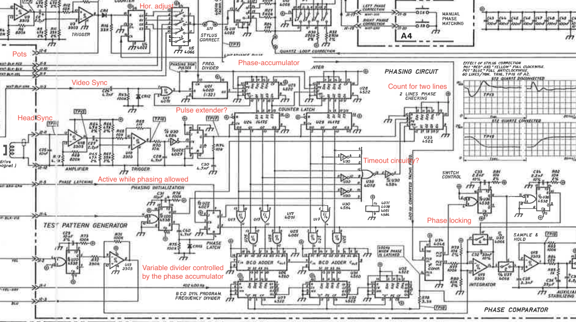
The schematic above shows the functionality.
The design is clever, I do feel that it could probably have been implemented in a simpler way, but it's a good example of a fairly sophisticated control system implemented using the then modern 4000 series of CMOS logic.
The Issue
After doing some analysis of the circuitry and probing the video and tachometers, I determined that the video sync pulse should be 90° off the phasing tachometer signal.
I made a test loop recording that contained nothing but synchronisation pulses, allowing me to quickly start/stop the fax to test the sync circuitry.
I had good tachometer pulses, and good video sync pulses, but the phasing circuitry appeared to only apply a slight fixed speed offset (1% faster) instead of adjusting the frequency to lock.
Probing U33 (the head pulse divider), I found no activity whatsoever, this should be receiving tachometer pulses. Tracing back, I found U30 pin 2 was stuck low, this is the small Schmitt trigger inverter that drives the tachometer signal to the phase accumulator latches and frequency divider.
I also found another inverter output in the same chip that seemed bad, but this didn't seem to affect the primary function.
Lifting pin 2 and shorting the pad to pin 1 (bypassing the inverter), I immediately saw the phasing circuitry start to operate! Since the tachometer pulse polarity was now wrong it locked in slightly offset, but this was repeatable, which is a good sign.
Above a looped recording was played two times, showing repeatable results!
A replacement 4584 hex Schmitt trigger inverter has been ordered, and is expected to fully correct the issue. A 4069 non-Schmitt inverter is installed temporarily, and functioning quite well.
I had noticed some occasional phase glitches during poor signal reception previously, I now suspect this issue may have been caused by the failure of the phasing circuitry. This may have been left partially active, allowing it to occasionally try to phase even after it should have terminated.
What Do The Potentiometers Do?
The front panel potentiometers are in fact the horizontal adjust feature. Measuring the Stylus Correct strap during operation made this pretty clear.
The way it works: during printing, the 4066 switch cycles through each potentiometer in turn, applying the potentiometer voltage to the speed reference signal (which is normally crystal locked by the speed PLL).
This applies a dynamic speed shift, shifting the phase temporarily. This allows fine adjustment of the three heads in the horizontal direction without bending the styluses around.
What's It Like?
Very cool, everyone loves weather faxes.