King KA-42B ADF Antenna System

The King KA-42B ADF antenna is a neat little 3-in-1 antenna-pod for aircraft. With some minor[0] effort it can be used as a pretty good HF reception antenna.
[0] for certain definitions of "minor"
Table of Contents
ADF & The KA-42B
The King KA-42B antenna is an aeronautical navigation antenna, likely intended for use in general-aviation and small commercial aircraft. It can be found used for relatively low prices on sites such as eBay.
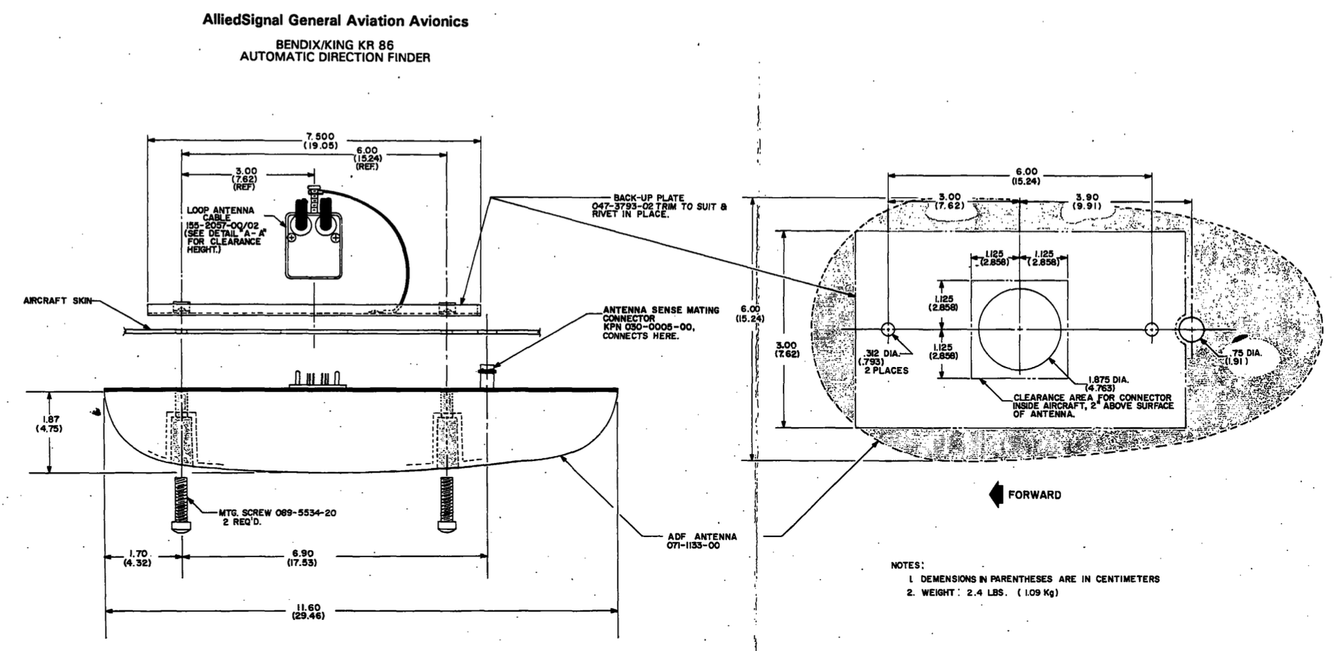
The function of the antenna and the associated electronics & display devices is to implement "Automatic Direction Finding," which is also on occasion called a radio-compass. The occasion seems to be the 1940's and earlier.
What is ADF?
ADF is a subset of Radio Direction Finding (RDF or simply DF), which is a technique developed some time before World War 2 for use in signals intelligence. Today this is usually referred to as ADF or NDB navigation; during WW2 it was usually referred to as a Radio Compass. RDF for Radio Direction Finding was a British code name for radar at the time, which is not directly related to ADF systems.
The goal is to determine the direction that a specific radio signal came from, and many techniques can be used to do this. The simplest technique is to get a high gain antenna and rotate it, the signal likely originates from whatever direction gives the strongest signal. This is basically how most radars work.
Unfortunately when the signal of interest has a wavelength of hundreds of meters, this becomes slightly impractical.
Fortunately, magnetic loop antennas have a nice property where their antenna diagrams are cardioids:

In the azimuth plane (for a vertically oriented loop), loop antennas have two deep null-responses, and very broad reception lobes.
The principle of a basic DF system is to rotate a loop antenna tuned to the frequency of interest, when the signal amplitude is minimal, the antenna is aligned to either the direction of the signal, or exactly opposite to it.
The loop antenna is sensitive to the H-field (magnetic), and by including an E-field (electric) antenna in the system the relative phase of the signal in the H and E-fields can resolve the ambiguity, and a single direction can be determined with reasonable certainty. The E-field antenna is essentially a "Mini-Whip" antenna.
Not So Brief Aside: A look at WW2-era navigational systems
World War 2-era systems were built using the loop+E-field antenna with a rotatable or fixed loop. The SCR-242 introduced ca. 1937 could be used with a fixed or rotatable loop + whip, and had a 180° ambiguity. The instruction manual says to just try steering the plane to see if the needle moves the right way to work out the ambiguity.
With the rotatable loop option the navigator (or radio operator, not sure) could manually rotate the loop to measure the bearing of a given station and perform e.g. triangulation across multiple beacons if available. It seems this generation of receiver was primarily intended as a "fly towards beacon" mode of operation, or as a very occasional triangulation receiver.
The later SCR-246 seems to have been a less capable variant with limited frequency coverage (up to 400 kHz) and no loop rotation option, but the loop was at least enclosed in a radome instead of just hanging in the wind.
B-17 "Flying Fortress"
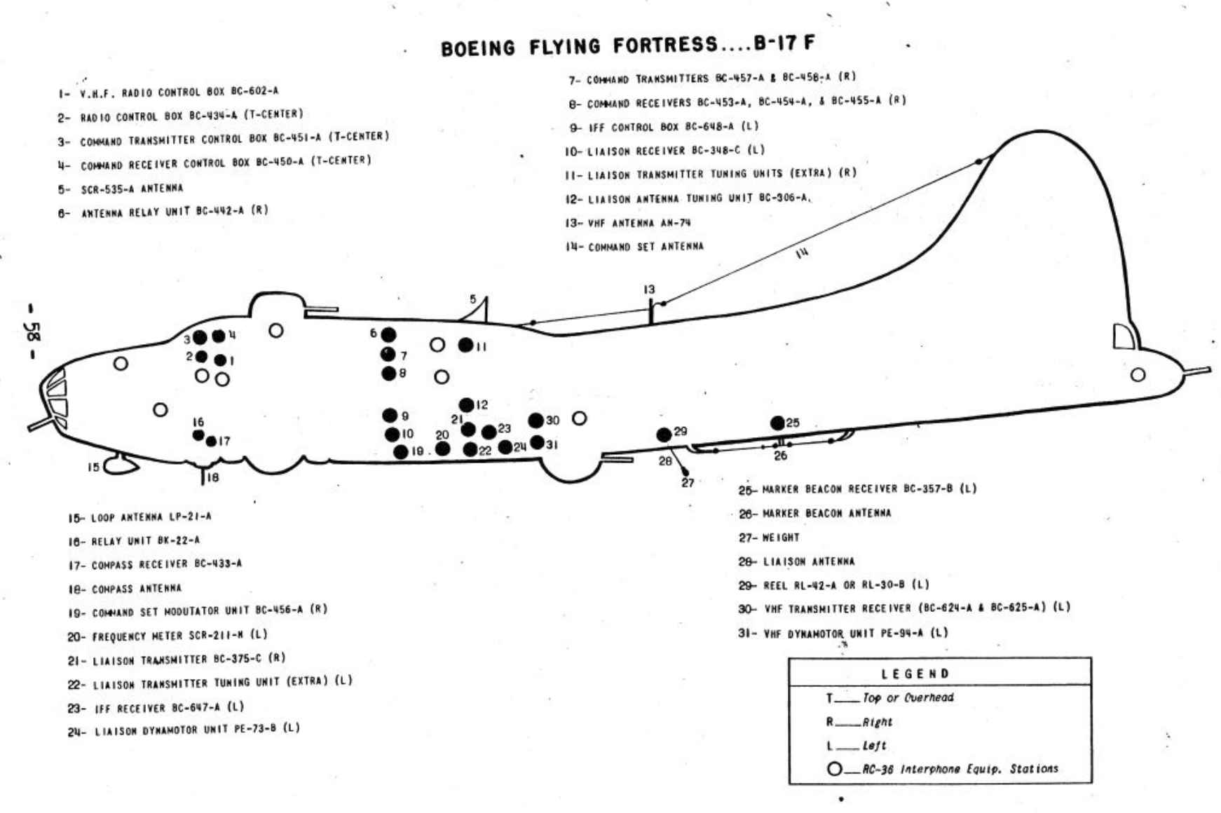
The B-17 "Flying Fortress" bomber plane is the breakout star of the 2024 popular TV series "Masters of the Air", where they were famously piloted by the whitest guys you've never forgotten; after all, we saw the unforgettable Buck from Arkansas starring alongside the main guy: Bucky (jr.) from Nebraska!
The plane was developed in the 1930's to counter the state of the art anti-air technology of the late 1920's and were used — very strategically — in what was basically WW1 cavalry charge tactics. I guess the outdated plane was well matched to outdated tactics, but you go to war with the army you have and hopefully you'll get a better one before you lose.
It's interesting to look back to a time where American military technology was just barely adequate vs. what the rest of the world was using. We do have to keep in mind that military expenditure in the US ca. 1930-1940 was around 2-3% of GDP, compared to 30-40% during WW2, and 8-10% during most of the Cold War (and around 5% in 2016; economic growth has been higher than military expenditure growth for the last few decades).
These canned goods planes mainly flew very slowly in tightly knit appetising box-formations in broad daylight, trying to deliver a full complement of 2-3 small bombs hopefully to the same continent as a ball bearing factory outside Schweinfurt. The long flights were mostly passed developing frostbite in intimate areas or trying vainly to put out the many random electrical fires the plane became famous for, interrupted briefly by playing catch with anti-air and fighter-plane cannon rounds. Frankly it's amazing anyone flew more than one mission.
Precision bombing was attempted using the exceptionally well marketed (and factoidly classified) Norden bombsight, trying to visually identify the target through the thickest rain clouds you've ever seen.
That aside, it seems to have had a pretty good radio compass, the SCR-269! It was pretty popular as the B-24, B-25, B-26, C-46, and C-54 also used this compass.
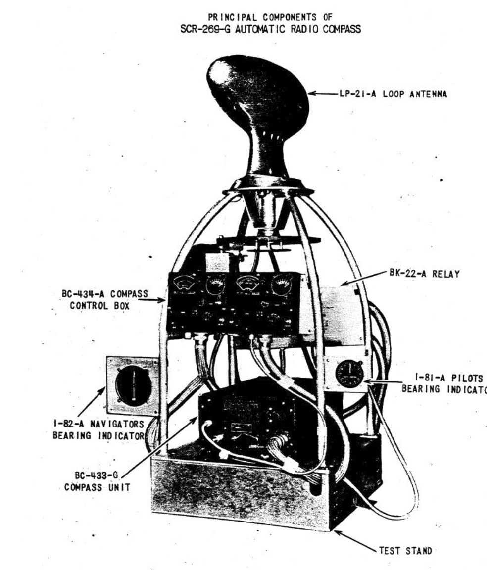
No manual seems to be available online, but this is noted as being "automatic" using a motor-driven loop with a true unambiguous bearing indicator. It was probably linked to the mag-compass to convert the plane-relative heading of the radio beacon into a compass heading. Frequency range was up to 1500 kHz, comparable to modern equipment.
Other Systems
Also worth noting that the only other noted radionavigation equipment listed in my source is e.g. the RC-43 "Marker Beacon" receiver.
Marker beacon is an older term for a Localiser, part of what we now collectively call ILS (Instrument Landing System). These receivers work in the "UHF" range of ~60-80 MHz (currently ~110-118 MHz is used) and provided crosstrack (side to side) information to the landing plane — I believe the principle of operation was identical to a modern system. No glideslope-system (vertical information) seems to have been present at that time.
They also had a few radio sets, including MW, HF, and crystal controlled VHF (the same VHF AM that planes still use).
Specialty equipment such as the hyperbolic Gee system and the various forms of radar such as H2S/H2X that would have been fitted during/after 1943 are not listed since they were likely far too classified to mention in a "RESTRICTED" document. These were also conspicuously absent in the TV series.
Gee was a passive-receiver British time-of-flight navigational system operating in the 30-90 MHz range that was also used by the USAAF in Europe as of 1943. In the Pacific Theatre they used LORAN(-A) which operated at 2 MHz (night) and 7 MHz (day) for extended range though probably worse accuracy. They also mostly flew B-24's.
At a high-level the early LORAN and Gee systems were functionally the same, but the later LORAN-C (100 kHz) lived until the 2000's when GPS finally killed it.
eLORAN
Hellen Systems Inc. acquired a U.K. (Ofcom) license to operate a new eLORAN service in 2024 (at a the eye-watering cost of £200 per year!), indicating that it may come back yet. Note that their website hasn't been updated since 2020, but some reporting in late 2023 and early 2024 indicates there is something happening in this field.
See also Omega, an even longer range system that had a similar life-span but required atomic clocks in the transmitter sites.
H2S
H2S/H2X were "centrimetric" ground scanning radar sets that could more or less make a top-down map of the surrounding area. Early H2S used a 10 cm wavelength (~3 GHz; S-band), later and better systems including H2X operated near ~10 GHz (3 cm; X-band). Some later systems moved to 1.25 cm wavelengths (K-band), and though resolution was better, the range wasn't great since this wavelength range is readily absorbed by water and the whole point was to see through wet clouds.
The K-band variant apparently did see some success in Mosquito planes doing lower level tactical bombing and attack raids towards the end of the war, and as a ground surveillance radar for Army use. The post-war V-bomber H2S IX/IXA systems used a higher power 3 cm magnetron transmitter[1].
See this fantastic video about the post-WW2 V-bomber navigational system, which while more advanced was fundamentally very similar: Navigation and Bombing System Mk1, V Bomber, Valiant, Victor & Vulcan avionics (posted by Spen Crowson, 2021).
[1] Sir Bernard Lovell, ECHOES OF WAR: The Story of H2S Radar, Chapter 30 et al.
Back to ADF
Getting back to ADF (took a while): Eliminating moving parts is generally good for reliability, and it turns out that using two loop antenna oriented 90° from each other (orthogonally) can be used with only slightly more complex circuitry. Using fairly simple electronics involving a lot of transformer-magic, two loop antennas can be combined with a variable phase offset to synthesise a single loop antenna with variable azimuth angle.
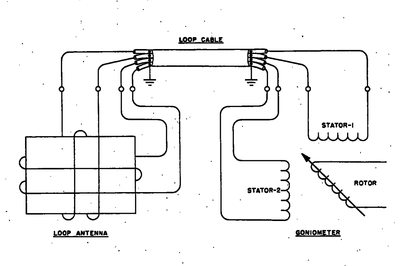
Above the connection of the loops to a goniometer indicator is shown, the rotor is driven by a signal derived from the E-field, and this adds up to a direction indication. The actual hookup is through various amplifiers and matching networks, but the principle holds.
Why is ADF?
An ADF system is a somewhat obsolete radio-navigation technique, the principle is to use an ADF receiver in the airplane to indicate the relative direction to a radio transmitter. The transmitter is usually a Non-Directional Beacon (NDB, no big deal), which are still found near various airports and transmit in the 200-400 kHz range.
Most ADF receivers cover the 100-1700 kHz range, making them capable of navigating to NDB's, as well as long-wave and medium-wave AM transmitters. Note that many AM transmitters are simulcast, with multiple transmitters used at various sites all transmitting the same frequency, making such stations unusable for radio-navigation.
One of the first electronic warfare (EW) actions taken by the British at the outbreak of WW2 was to switch all BBC long/medium wave transmitters to operate on the same frequency. Otherwise, enemy night-bombers could have used these transmitters as navigational beacons[2].
NDBs transmit a slow morse-code AM signal giving their station ID, and ADF receivers generally have an audio output allowing monitoring of this signal to confirm the correct stations is being received. Because of this feature they are also usable as medium-wave radio receivers.

In principle multiple ADF receivers can be used to triangulate the aircraft position using 3 or more reference stations as shown above. I don't think this was done in practice though.
Note that this is not the same as e.g. LORAN, OMEGA, and Decca navigational systems, those systems all rely on measurement of relative time differences between reference stations (hyperbolic navigation). This system would purely use angle of arrival information instead.
In practice a single receiver is used, and distance and relative angle to a given station can be resolved by flying the aircraft in specific directions for some time, knowing the approximate ground-speed and magnetic heading — this concept is shown below.

The angular speed of the ADF receiver then gives a measure of distance, and the difference between ADF and magnetic compass angle can be used to tell the direction, allowing for surprisingly precise navigation. In the example above the calculation of range is basically trigonometric. Obviously another variation is to simply point the plane at the NDB, upon reaching it the reading will reverse, and the next NDB in the route can be tuned.
Unfortunately, this navigation technique does require you to know which station you're tuned to, which might not be obvious if frequencies are reused and you really have no idea where in the world you have ended up. This was not the cause of the crash of Varig Flight 254, but it contributed to compounding the error.
See also this — excellent as always — article on the DAG-1 MW/HF DF receiver by Cryptomuseum.
A more advanced and modern concept is VHF Omnidirectional Range (VOR), which uses a special signal modulation that allows direct angle measurement using a single non-directional antenna, and is often paired with Distance Measuring Equipment (DME) which is a separate transponder system using two-way time-of-flight measurement principles to determine range. VOR-DME can then be used to navigate between stations, and it allows sufficient precision to intercept an Instrument Landing System (ILS) localiser to precision landings.
[1] Alfred Price, Instruments of Darkness (second edition ca. 1977), page 33.
The KA-42B
The KA-42B is an ADF antenna, it is a "modern" type that includes all three antennas needed. Earlier models of ADF antenna only included the loop antennas in the antenna-pod, and expected a whip antenna to be installed on top of the aircraft to provide the E-field channel.
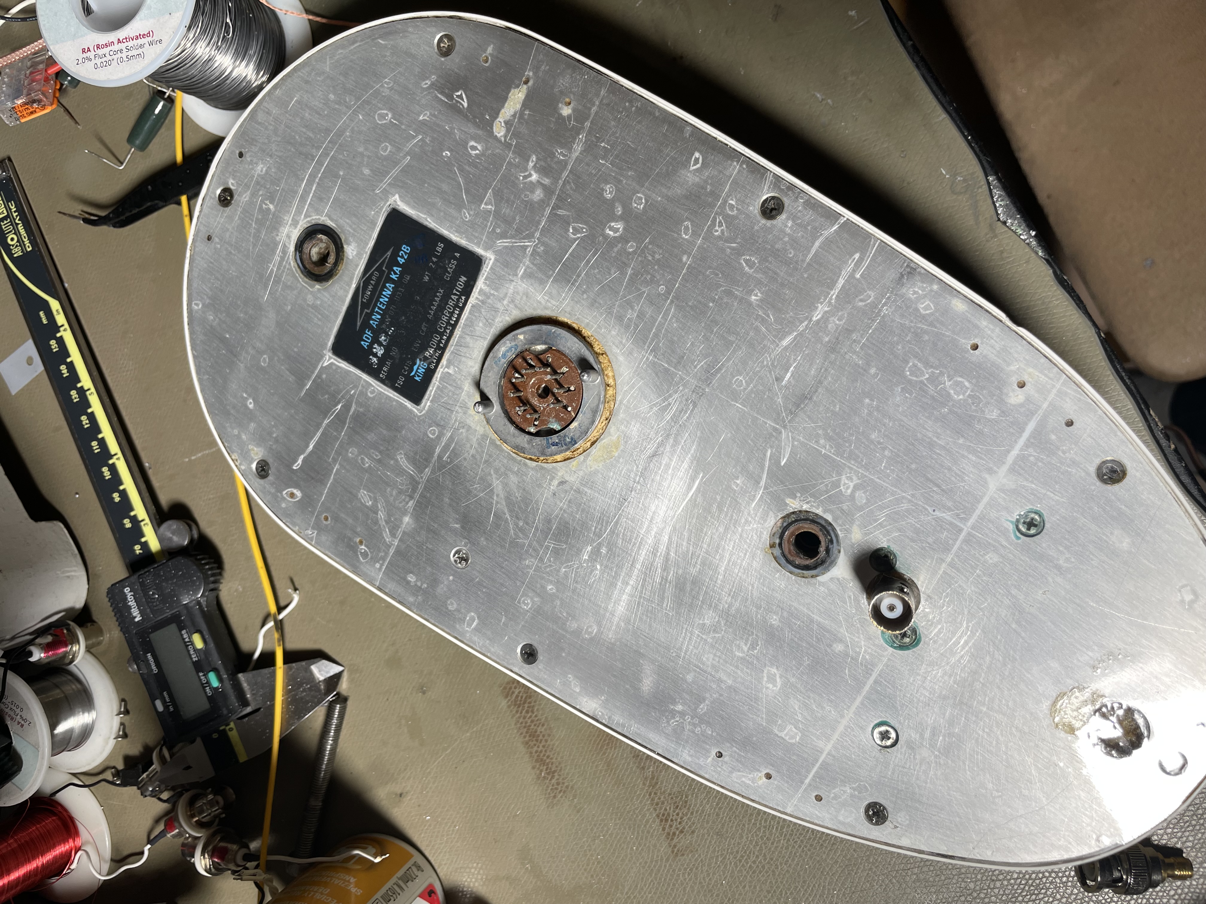
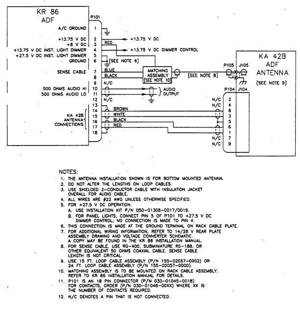
Connections are via a BNC plug for the E-field whip (the whip is active, and requires around 8 V bias), and a tube socket is used for the loop connections.
Outdoor Unit
Below the block diagram of the outdoor antenna unit is shown, this assembly is installed in an aluminium box that the antenna is mounted to.

Above the block diagram of the antenna and antenna-near electronics are shown. The antenna consist of the actual antenna (left) with E-field sensor and orthogonal loops and associated pre-amplifiers. Each antenna-signal is amplified in variable-gain amplifiers to normalise the RF levels, and the signals are frequency shifted in mixers and combined.
A clock reference signal (VCXO⁄4) is inserted, and the combined FDM multiplex is levelled in another AGC amplifier before being applied to the laser diode. An ESP-32 microcontroller controls the AGC loops and provides a web interface to control and monitor the signals.
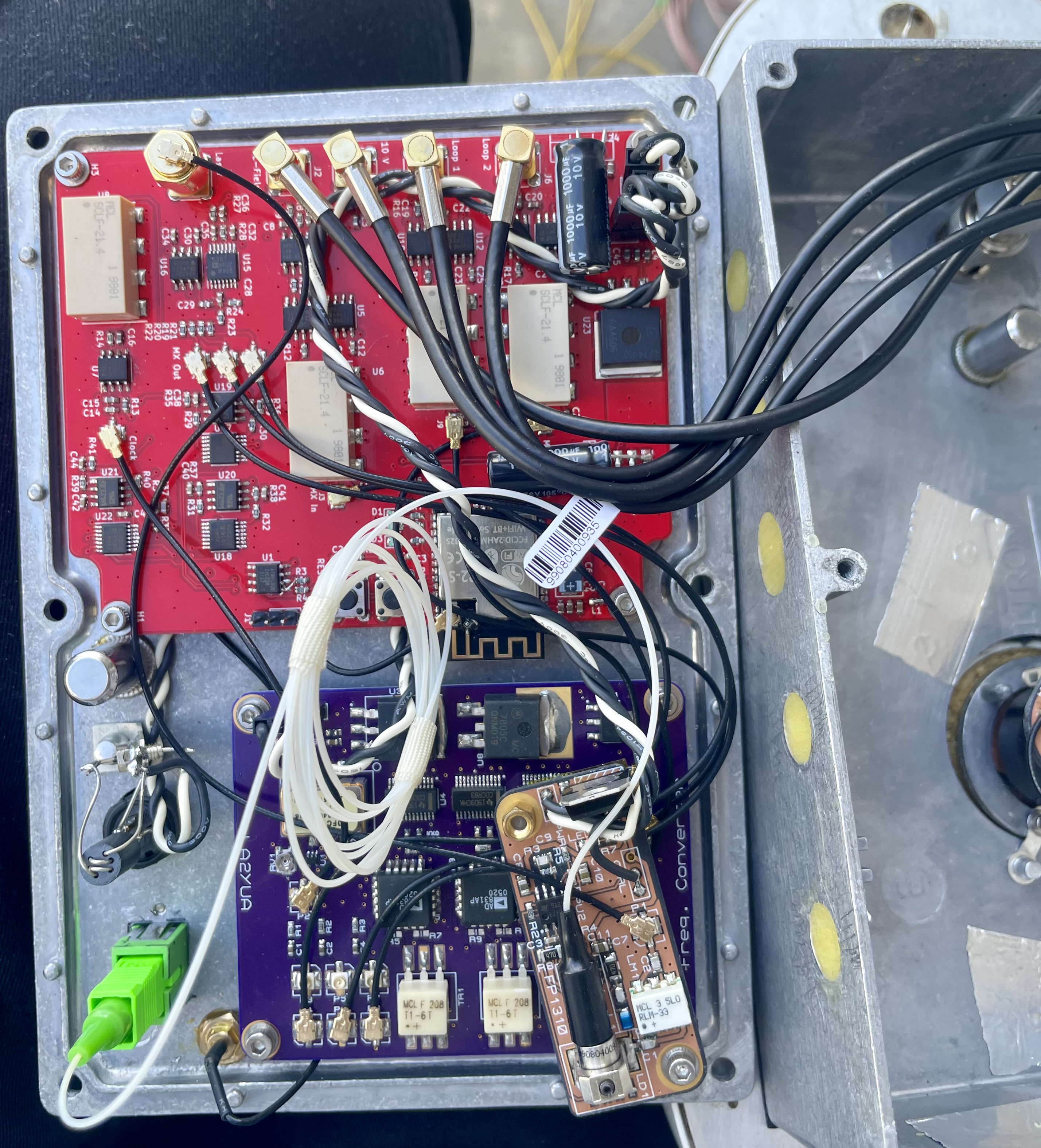
The primary electronics assembly is installed in the base-plate of the antenna electronics box, shown below. The red PCA is the FDM Combiner, and the purple board is the mixer-assembly (which was made first). The laser driver electronics were installed later. Power is via a SP-13 3-pin connector, it runs off a standard 12 V power supply, which is regulated to the usual 10, 5, and 3.3 V DC internally.
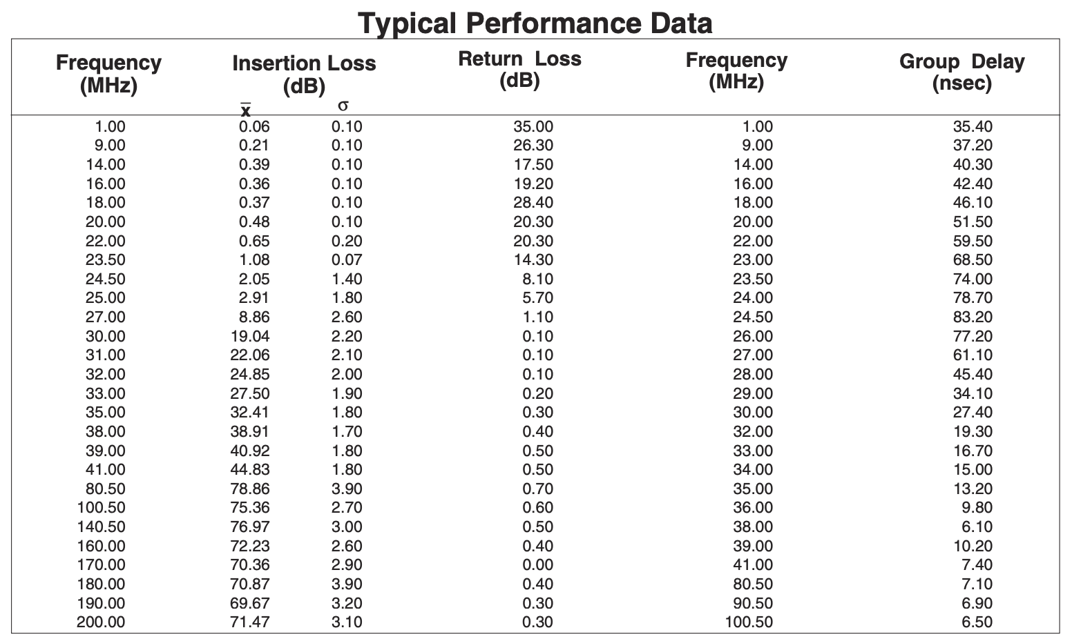
The RF bandwidth is set using Mini-Circuits SCLF-21.4 filters, I got a good deal on eBay for 25 of them and made extensive use of them in this project. The typical performance is shown below, they more or less eliminate anything above 30 MHz.

Above we see the idealised output spectrum of the multiplex, showing the clock carrier and three double-sideband/AM carriers. The frequencies align such that the three signals should have around 10 MHz of space between them. The three carrier frequencies are fairly suppressed, but some leakage is present due to imperfections in the mixers, this will be useful later.
I had intended to use this antenna as a long & medium-wave reception antenna, though as seen below I found that this didn't perform particularly well there, but fortunately the short-wave performance is quite good up to around 18 MHz.
Note that while the system could be used to implement a null-steering antenna, this is not possible to do in a broad-band system, the primary use of this system is to simply use one of the three channels as the receiver. Orienting the loops such that one of the antenna nulls falls in the direction of noise is then a compromise, but initial testing seemed promising.
Preamplifiers
The loop antennas have an inductance of around 100 µH, and they produce extremely small signal currents. This is not unexpected since they are physically quite small.
In system they would be connected to a frequency specific matching network which would make then resonant, but I wanted a broad-band system. To provide initial amplification, a S982 dual-gate FET pre-amplifier is used. This amplifier is modified vs. the schematic shown below by hard-wiring gain to maximum, and by connecting a feedback resistor from the drain to the RF gate (AC coupled). This turns it into a trans-impedance amplifier (TIA).
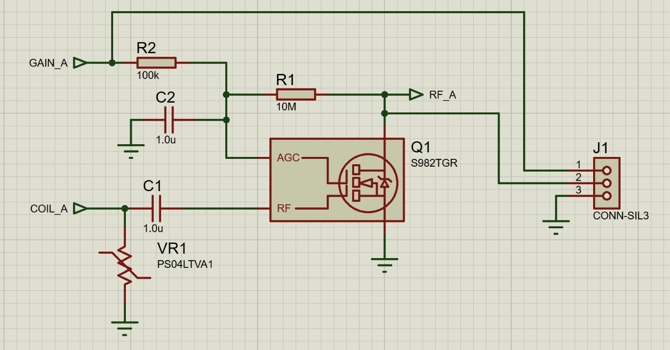
This provides the initial amplification, and this is immediately fed into a pre-amplifier PCA:
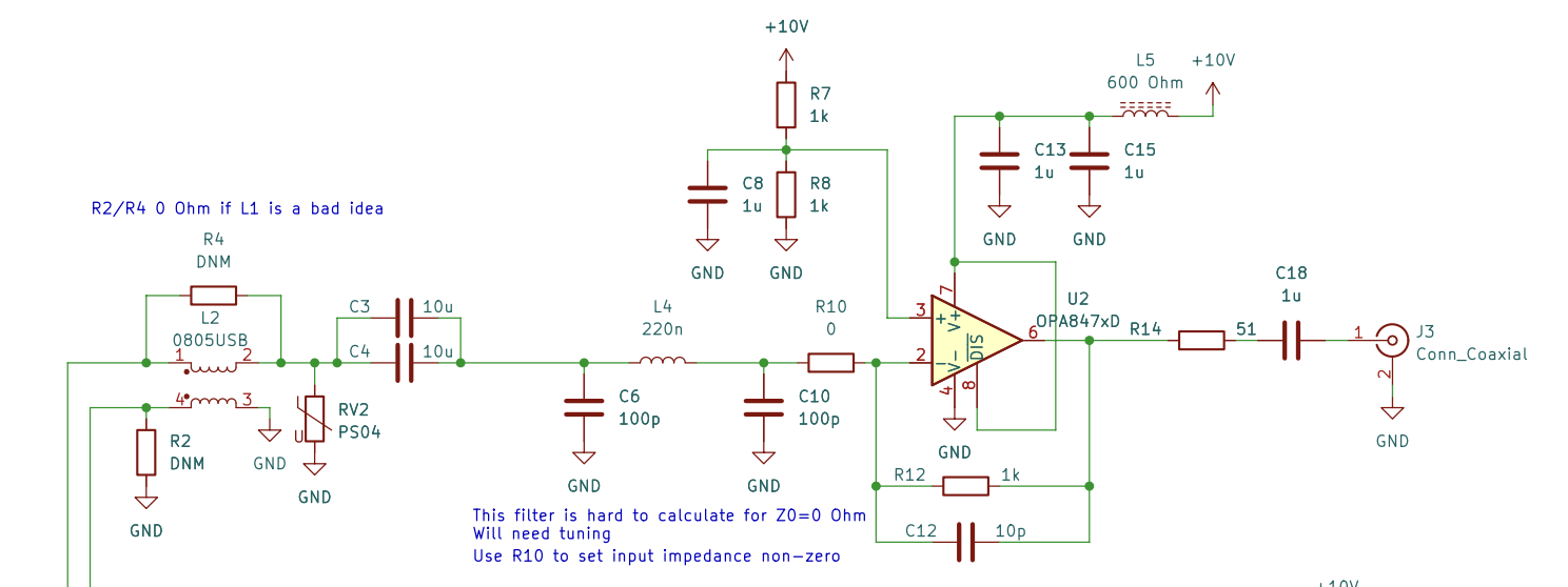
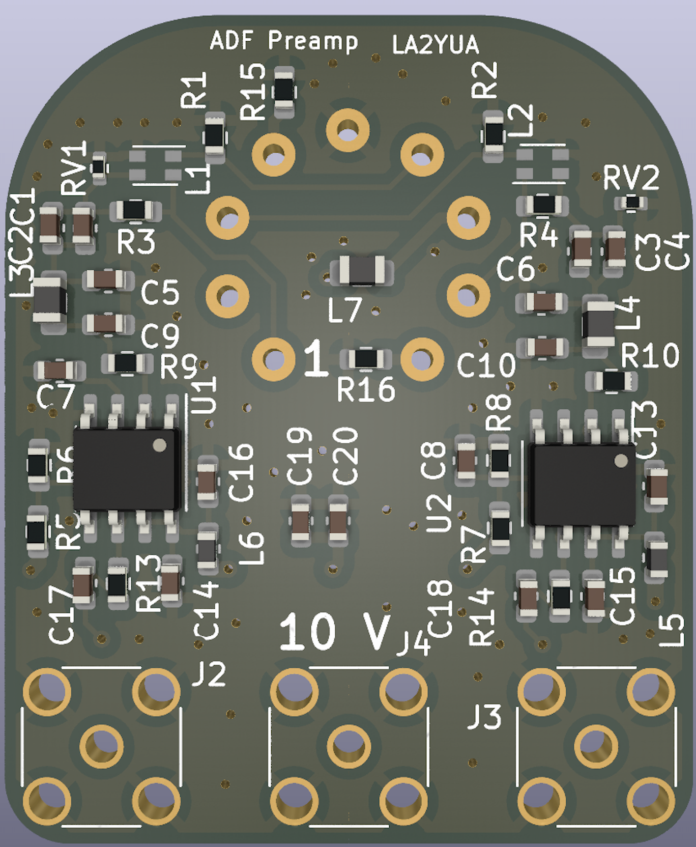
This pre-amplifier was intended to be the only preamp, but I found that achieving the required total gain with just the operational amplifiers was not practical without oscillations. As such the FET pre-amp was installed between this amplifier and the actual loop.
This method of amplification has higher sensitivity at higher frequencies (the H-field induces a current in the coil, the voltage follows the 2πfL impedance of the loop).
I found that the loop channels seemed to perform best above 3 MHz, and that performance below 3 MHz was quite poor, while performance in the 10-15 MHz range often outperformed the Mini-Whip. The E-field performance was generally somewhat worse than the Mini-Whip, so I think that implementation is better than the King antenna.
Frequency Conversion
The frequency conversion is as usual done with AD831 high power IC mixers, these are still some of the best on the market for this frequency range. The output opamps are not in use for these converters, instead the current mode output is used through an RF balun.
To generate the reference frequencies, a 77.76 MHz VCXO is used as the core, this is divided by 2 and 4, and these divided frequencies are fed to CDCR83 clock generators. This configuration was selected since I already had the parts laying around.
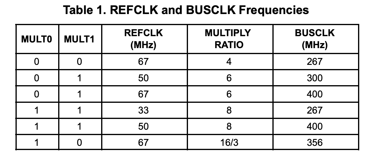
Unfortunately the division ratios and clock generators are not guaranteed to keep a specific phase relative to the 19.44 MHz (77.76÷4) reference frequency, necessitating the active phase alignment system in the indoor unit.
Control System
An ESP-32 is used as the outdoor unit controller, it mostly controls DACs that set the gain of the various channels, and monitors the power-detectors.
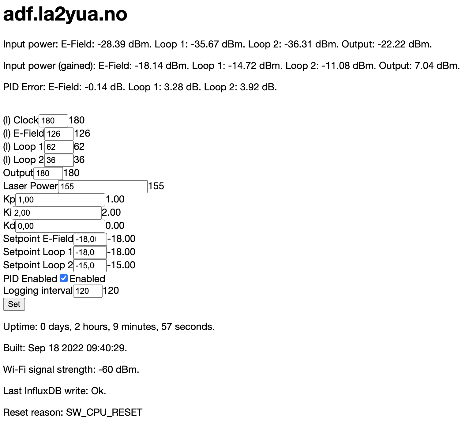
Above the highly sophisticated hypertext based control interface is shown, it implements both monitoring of levels and gain control, and control of target set points and PID regulator parameters.
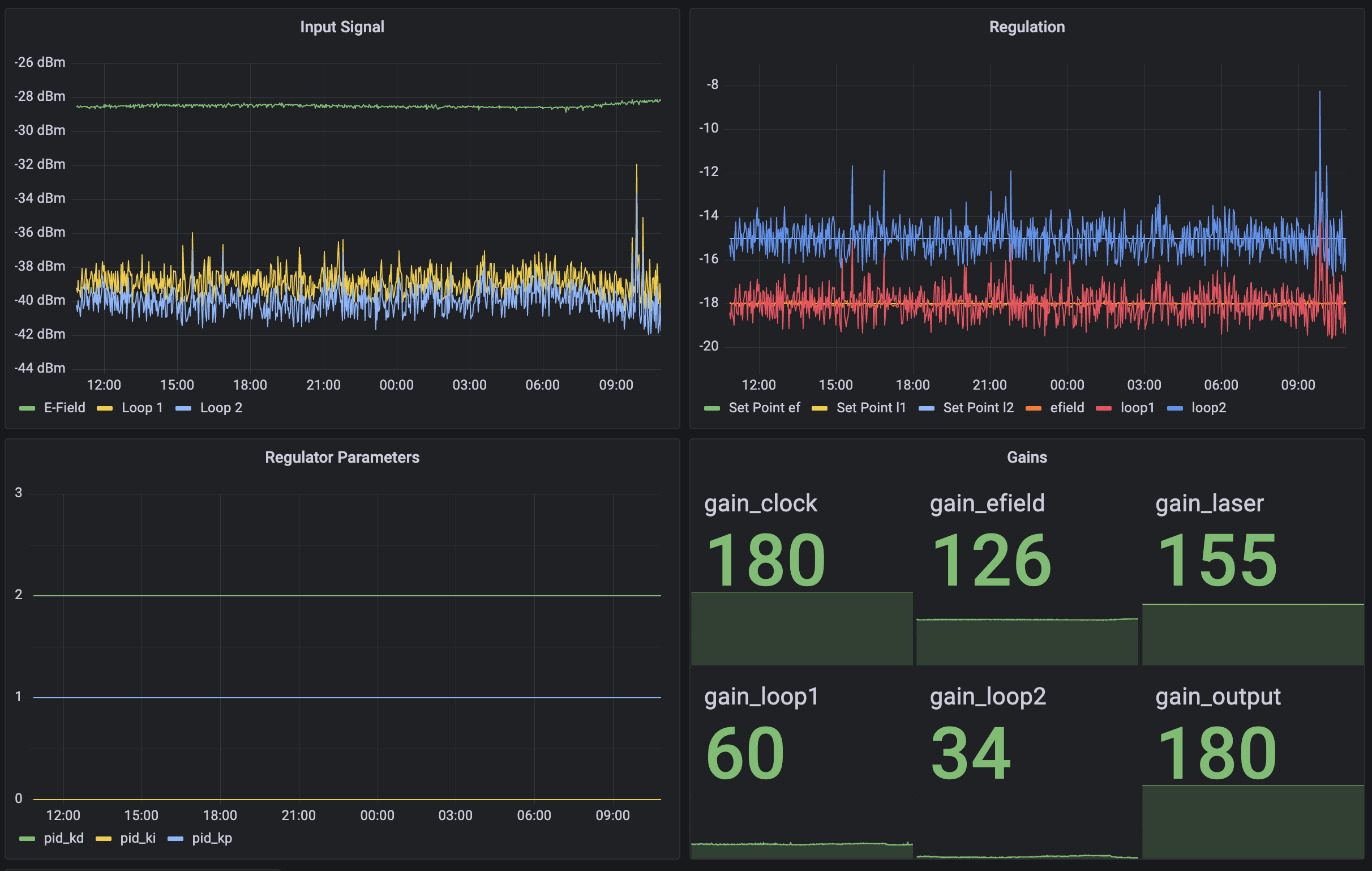
Above we see a slightly more sophisticated hypertext interface of type "Grafana," which shows the ADF antenna status vs. time.
Indoor Unit
The indoor unit takes the multiplexed signal and converts one of the carriers to baseband for use by standard HF receivers. The reference indoor unit is shown, but since the system is fiber optic, alternate indoor units can be connected if desired.
Demodulator Design

The demodulator takes the FDM multiplex signal and recovers one of them to baseband. The multiplex includes a clock reference at 19.44 MHz, this is recovered by a low pass filter, and amplified. The amplified clock reference is used to phase lock a local VCXO using a basic XOR PLL, this ensures that the local oscillator will be at the exact right frequency.
The demodulator is powered by 5 & 12 V supplies, and pulls around 1 W.
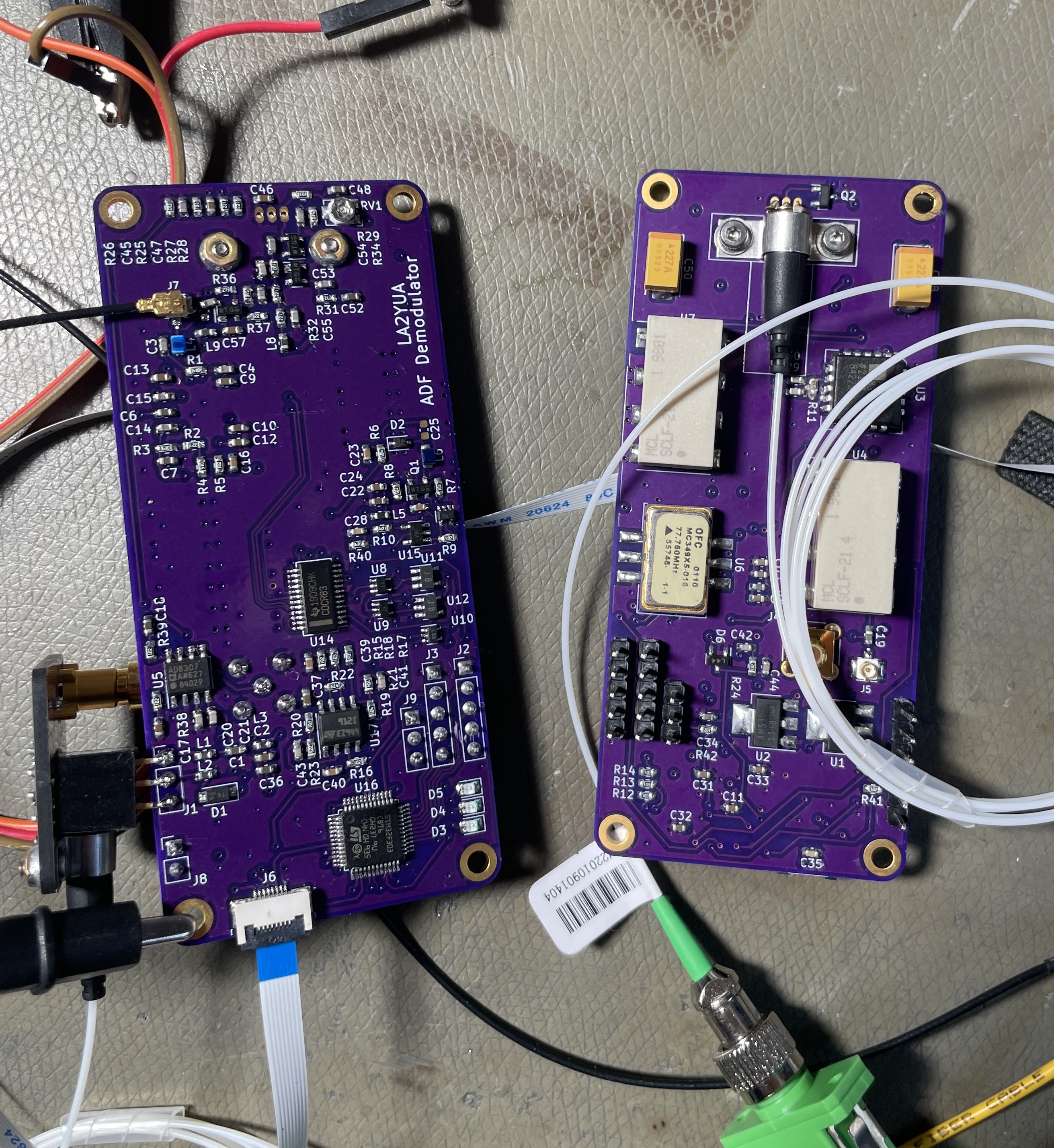
Above two demodulators are shown during initial development testing, at this time the internal TIA was not functioning well, so a stand-alone TIA was used instead (external TIA mounted to the bottom left on the leftmost board).
The design of the transmitter clock generator means that the generated local oscillator and carrier-frequency can have one of multiple stable phase relationships. Slight phase errors are not of major concern, but 90 or 270° phase offsets correspond to null-responses and must be avoided. The demodulator needs to determine what phase is applicable and correct, this is done by measuring the D.C. output level of the down-converting mixer.
The D.C. level of the mixer output will follow the sine of the relative phase between the LO and the incoming carrier. By controlling a voltage controlled phase shifter inserted in the clock recovery circuitry, the LO vs. carrier phase can be adjusted. Automatic adjustment is performed by sweeping the phase shifter to reach the maximum mixer D.C. voltage, which corresponds to the optimal phase alignment.

This adjustment is repeated every time a new carrier-frequency is selected, or if the optical signal is removed and reinserted.
Note that if additional filtering were used in the antenna, the transmission scheme could be single sideband, and many of these issues would be avoided.
Automatic Phasing System
The implementation of automatic phasing is not the most reliable thing in the world, but tweaking has made it usable.
The STM32F303 ADC is used to sample the mixer DC level, while the built in DAC is used to drive a BB152 varactor diode, controlling the phase. The sensing circuitry is shown below.
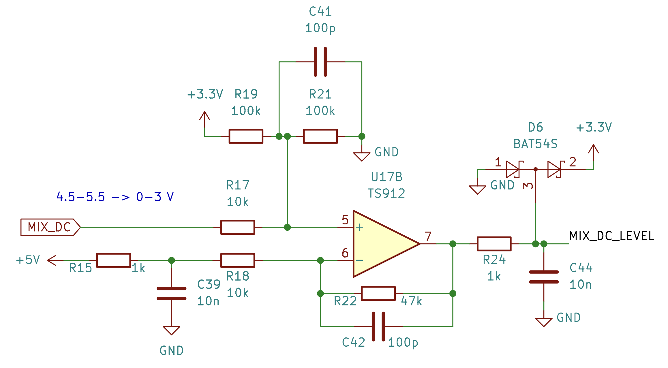
And the PLL circuitry is shown below, the RF_CLOCK signal is tapped from the TIA output. The BB152 varactor diode and L6 form a series resonant circuit, where the phase shift is controlled by the applied voltage. An XOR gate and low pass filter do the rest.

The phasing is performed in two steps, a coarse and fine search. The coarse search is performed in wide steps, and this measurement was (after considerable trial and error) found to work best when the criteria was the highest derivative. To actually evaluate which sample index is the best match, 5 adjacent samples are summed before comparison.
Below is a sample phase-sweep (values are derivatives), we can see that there is a periodicity to the table, and the peaks and valleys are at least 4-5 samples wide. This source will generally land around index 7 or 12, where the 5-27 index range is the allowed search range.
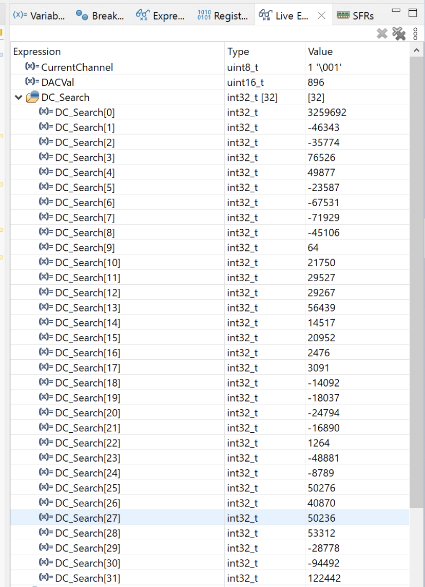
After coarse search, the phase-adjust is swept across a narrower range centered on the found coarse index, but this search attempts to minimise the derivative. I'm not sure why this works best, but this setup appears to achieve fairly optimal matching and it seems to be quite repeatable.
The optimal match is fairly stable, so the phasing result is stored per antenna channel, and is reset when channel 0 (i.e. "Off") is set. This way the phasing can be retried if it did fail to achieve optimal results, or if e.g. the external transmitter were lost. This automatic phasing is also performed on startup.
The system works reasonably well, but will need further adjustment and testing before it can be considered "good."
Receiver Trans-Impedance Amplifier
To receive the signal, a broad-band trans-impedance amplifier (TIA) was required, and a high performance 10 kΩ/300 MHz cascoded TIA was included along with the usual PIN diode optical receiver.
This design had been successfully tested on 2-layer boards, and to summarise: it didn't work. I believe the major issue is a combination of putting the 3.3 V rail power plane under the TIA circuitry, causing capacitive coupling, and slightly less optimal layout.
The TIA was therefore prone to self-oscillation and this was compounded by the use of high speed clocks on the 3.3 V power net, which tended to pump the oscillating TIA, causing massive noise and spikes.
The fix was to simply keep using the 2-layer standalone TIA design, this means the footprint of the design increases slightly but otherwise the external TIA has identical performance to what was intended here.
The external TIA will be the subject of a future article, as it is generally a useful design, but by it's high speed discrete nature, a rather sensitive one.
Summary
The ADF antenna is a fairly usable HF receiving antenna, offering a decent 3-in-1 package. The orthogonal loops are fairly useful, and for many stations I find that one is consistently the stronger (and it's not just that one is always better).
The very low output level from the loops in broad-band mode is an issue, and requires very careful pre-amplifier design.
The FDM multiplex transmission scheme could have been better implemented. The biggest issue is the automatic phasing system, which is a cludge and ideally should not have been required.
Future Work
The next big step after this is to integrate the demodulators into e.g. the 3021N receiver and my PlutoSDR system.
The 3021N integration is expected to take the form of an antenna selector PCA, with HFoF and ADF inputs, and room for 1-2 future work inputs (TBD what those will be).
PlutoSDR integration is the subject of a future article.
Addendum
Prototyping Effort
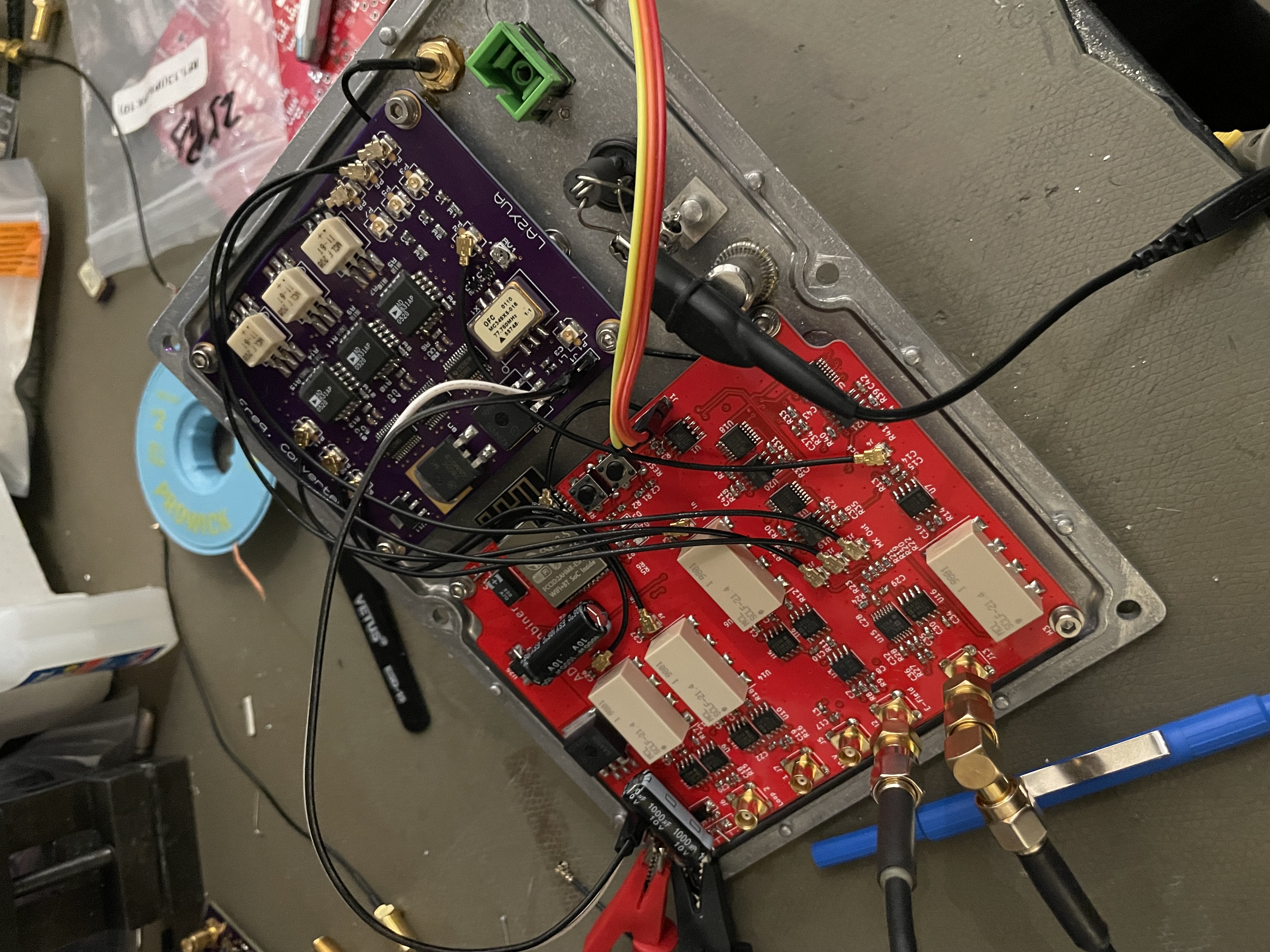
Below are some pictures of the development testing of the system, the very early tests used a flex PCB pre-amp (the FET pre-amp mentioned above) and discrete coax transmission. A later test used just the mixer-PCA, with a matching mixer-PCA inside providing all 3 antenna outputs, this led to the discovery of the LO vs. carrier phase issues.
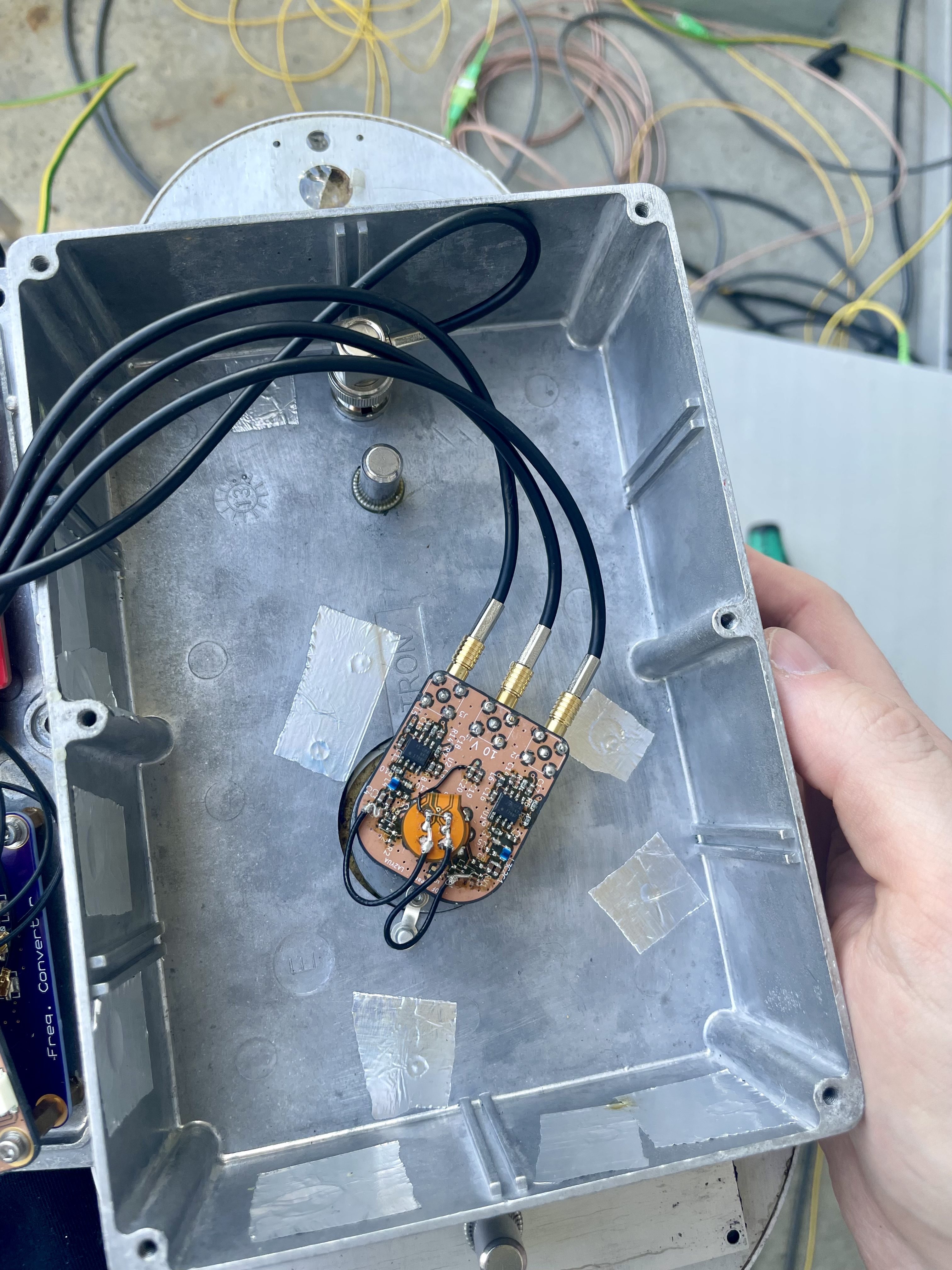
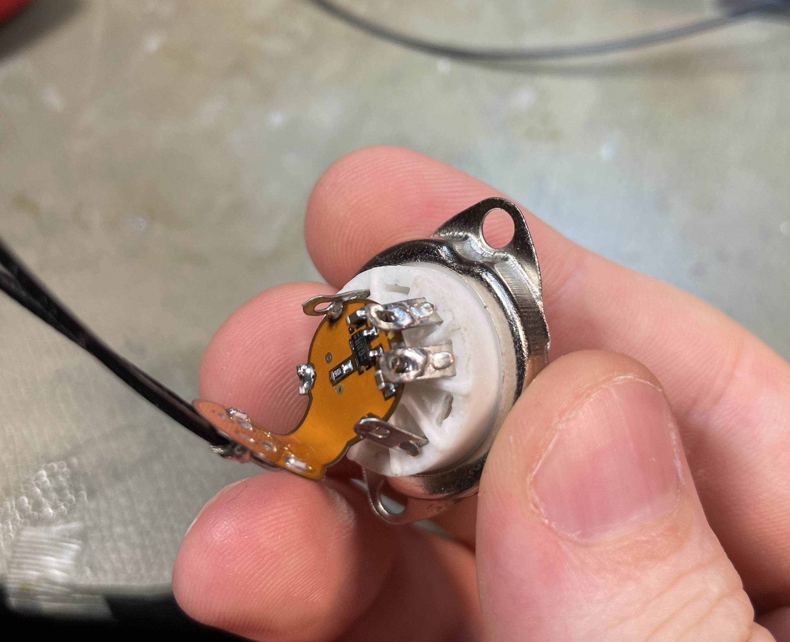
Below the antenna is mounted with a small active pre-amp board, the FET pre-amp is installed in a ceramic tube socket, and a closeup of the amplifier board is shown.
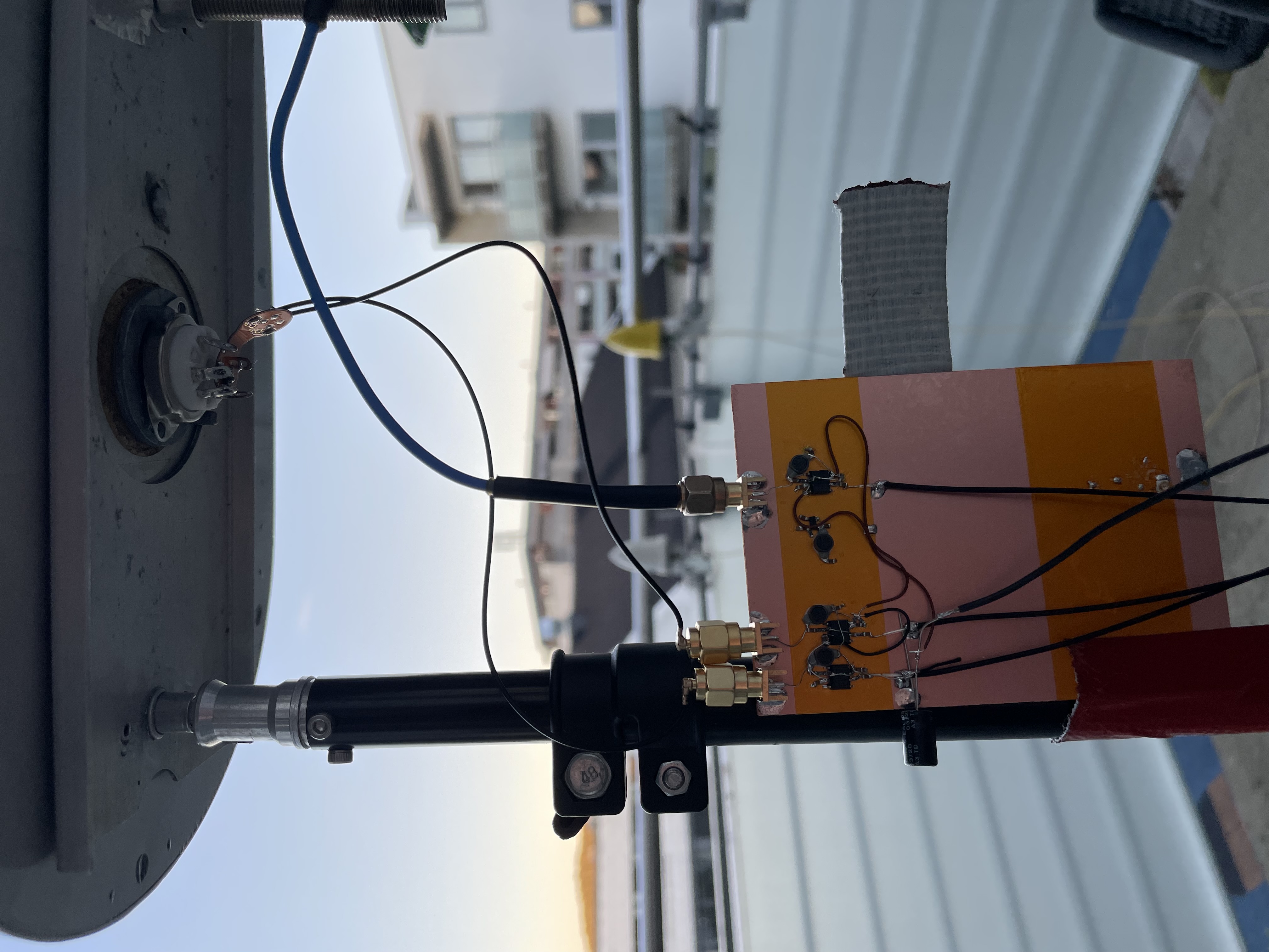
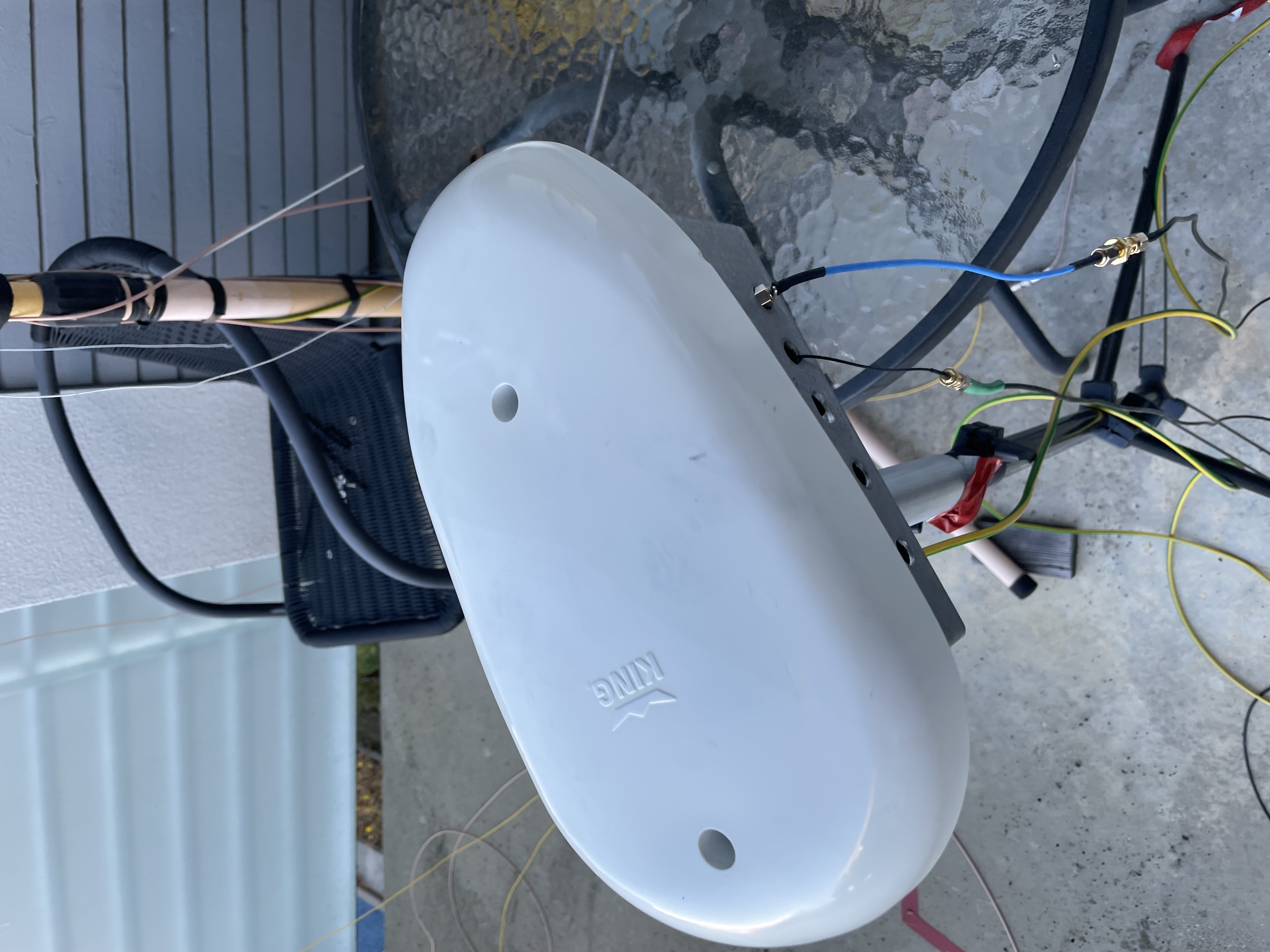
Below the antenna has been installed with the final box, but without full electronics integration. This was mainly testing the pre-amplifiers still. The box was recycled, with many holes drilled in the sides, I later filled these with epoxy resin and aluminium tape on the inside.
External TIA/Optical Receiver
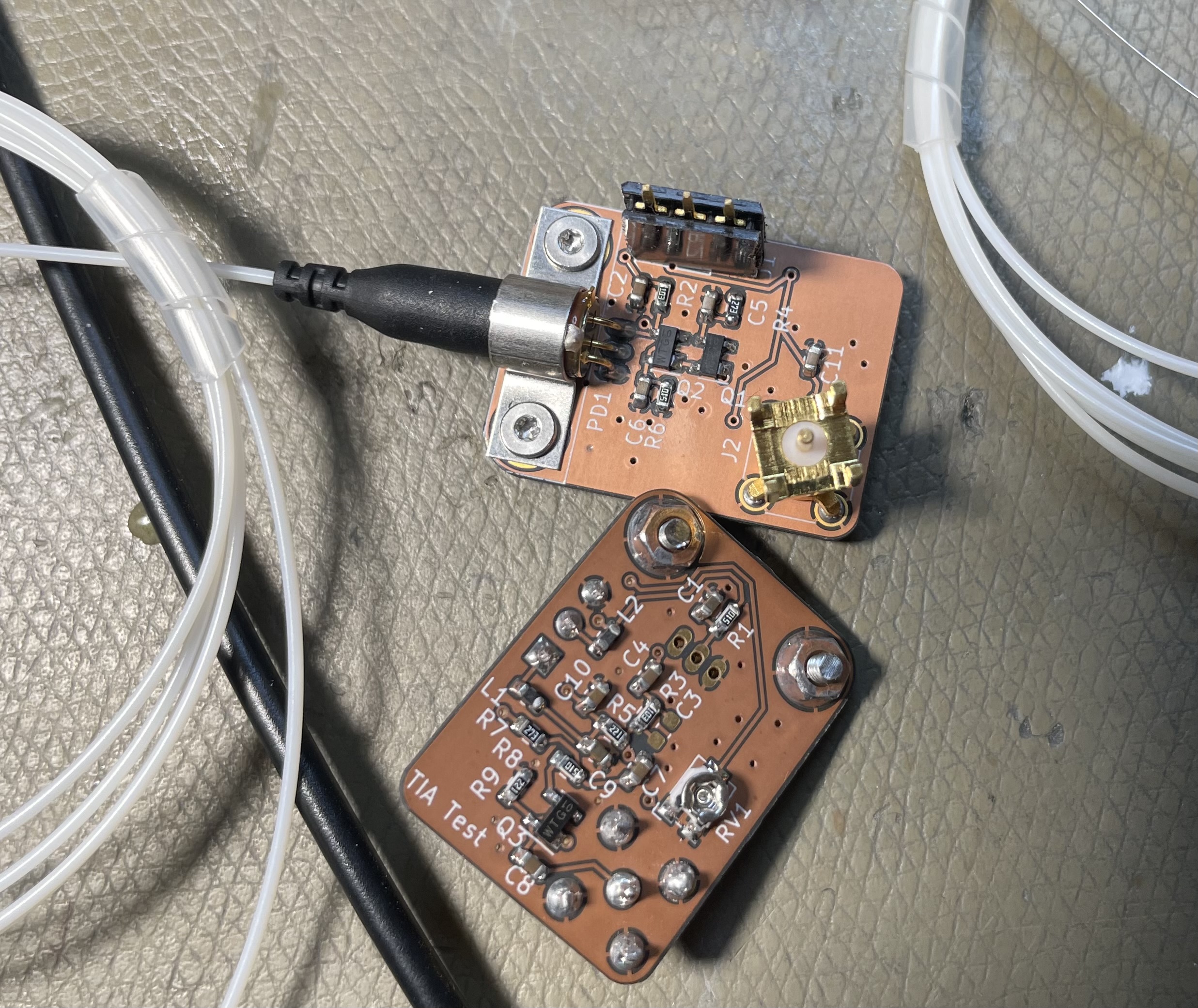
The external TIA (abbreviation for Thanks in Advance) mentioned above deserves a picture too, it's a design I put together in late 2022 for use with the Mini-Whip and ADF system. It was also hoped based on simulations that it would be suitable for VHF & UHF use, and I believe that it can be used up to around 1 GHz if gain tradeoffs are made.
It uses a 5 & 10 V power supply, though the 10 V supply does not need to be exact.
It is built as a reusable module, with pin headers for power and an MCX-F contact for RF output. A potentiometer adjusts the operating point, this must generally be set according to how much optical power is applied, though there is some margin.
Over all this is a pretty successful design, but as mentioned proper characterisation is for another day.