Vertex Standard VXR-9000 VHF High to VHF Low Conversion
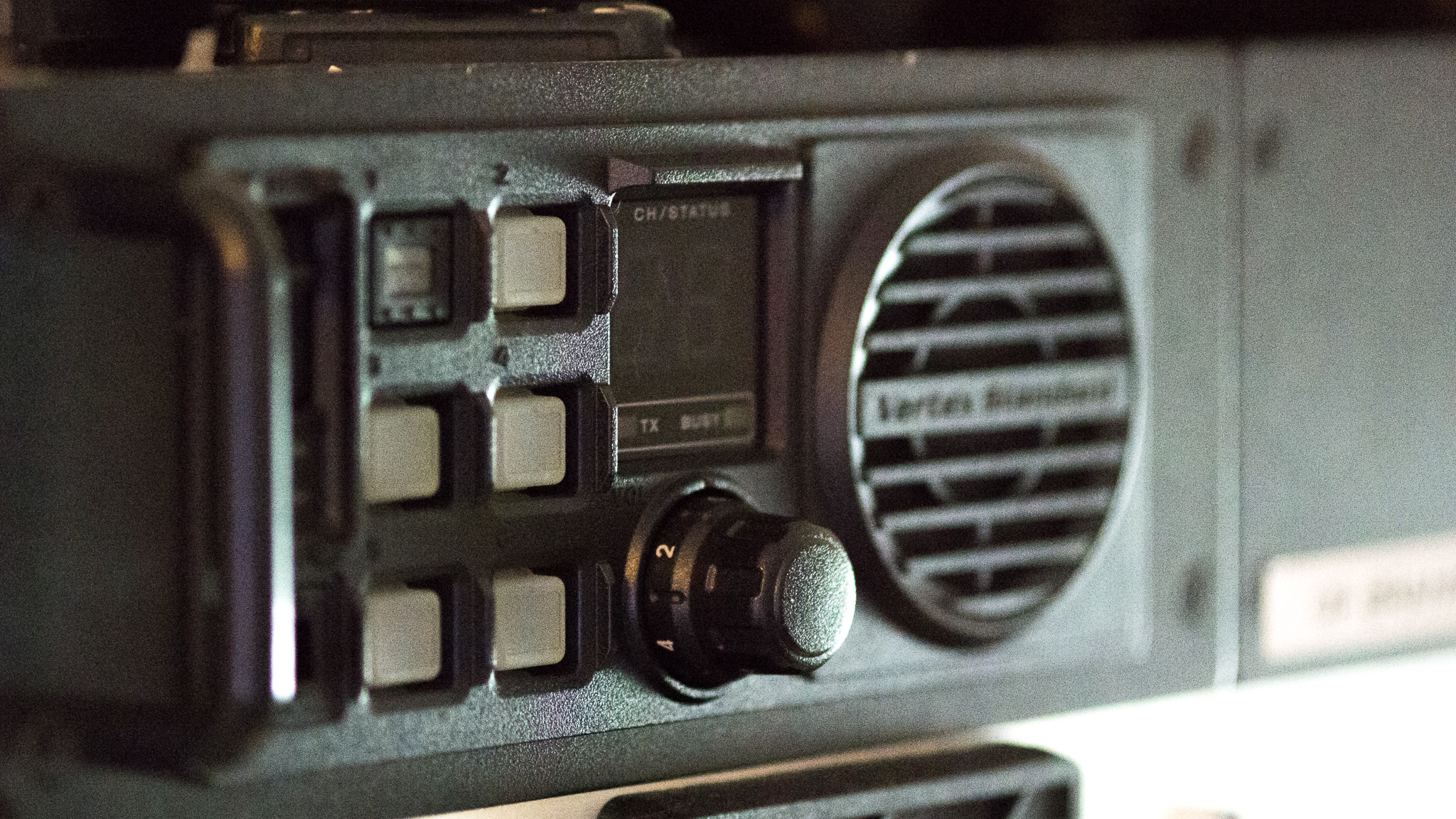
This page describes how to convert a VXR-9000 VHF C repeater to a VHF A version.
Table of Contents
This process was worked out for LA1N, Narviks ham radio group in Norway. A number of these repeaters were available in the VHF C variant which does not cover the 145 MHz band.
These repeaters were used by public services in the 160-170 MHz range, and are now "obsolete" due to the nationwide switch to TETRA.
Actual Hardware Differences
There are genuine BOM differences between the two versions; this includes VCO and filter part value changes. I found that all our units were capable of operation around 145 MHz without component changes but for lower frequencies this will probably not work.
Basic Steps
The following steps are required to convert a VHF C version:
- Read old programming
- Use the Factory Mode to change the HW type
- Set new calibration frequencies
- (Optional) Adjust VCO tuning
- Perform partial adjustment procedure
- (Optional) Perform full adjustment procedure
Required Tools
The following software, documentation and tooling is required to perform this modification:
- VXR-9000 Service Manual
- Windows XP to Windows 10 PC with a spare USB port
- Vertex Standard VPL-1 serial adapter cable or equivalent (see below)
- Vertex CE-60 Programming Software
- Power Supply 13.6-13.8 V, 10 A or so
- Power cable from your supply to 4 mm ring terminals (or the original power cable)
- DVM for probing D-Sub connectors
- RF signal generator with necessary to BNC connector
- 1mm flat head screw driver for VCO adjustment
- JRC no. 2 screw driver (Philips can be used if you're careful)
In addition, it's highly recommended to have the following:
- RF power meter, reasonably accurate for VHF use
- 50 W or more dummy load
Alternately, a radio test set such as a Wavetek 4015 with an appropriate cable set can substitute a number of test instruments.
Using an Icom OPC-478 with an adapter
The Icom OPC-478 is widely used in Icom HTs, and can be had very cheaply. Electrically it's identical to a VPL-1, and a simple adapter can be made to use it.
To make this adapter, a female 3.5mm stereo jack must be connected to an RJ-45 cable; connect the ring of the jack to the RJ-45 pin 5 (Ground), and the middle ring to pin 8 (Data).
Updated (2017-09-06):
The pinouts listed in the schematic for the VXR-9000 are mirrored; accordingly you have to connect pin 4 to the sleeve, and pin 1 to the ring (white/blue to sleeve; orange/white to the ring).
Updated (2017-09-17):
I believe the E9 issue is caused by an error writing programming data to flash. The only place to store the programming data is in the main CPU ROM, which is hardware write protected through the state of pin 66, FWE.
I was able to program my E9 repeater by making a shorter cable for example. I believe the relevant connection to make in the programming cable is:
Pin 2 (RJ-45 pinout, pin 7 in VXR speak) to pin 3 (6 in VXR speak) might be enough to counter this issue. Ideally this pin should be connected to a voltage higher than 9 V to properly enable the switch circuitry inside the radio. I've found that this is probably unnecessary, but your mileage may vary. Leaving it floating seems to have caused issues in any case.
As such I've made this drawing of my recommended cable, for connection to an Icom cable you just connect P1:1 to the data output of the Icom cable instead of using the diode.
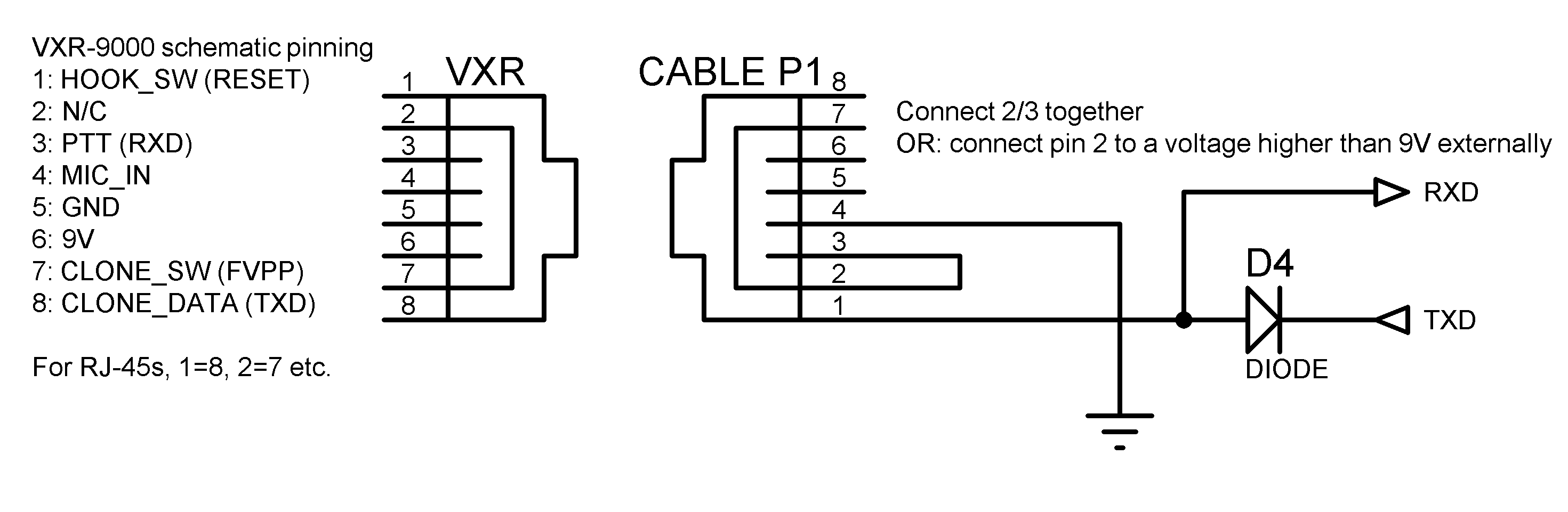
Ignore the RESET, RXD etc. lables, they're not used for programming or alignment but may be used for firmware upgrades (I have no info on how to do that).
Initial Setup
Software
Install CE-60, note that this will be installed under "VXR-9000 Series" in the start menu.
Interfacing to the Repeater
To power the repeater you can use the main power cable if you have it, or you can use the ring terminals designated as a backup power. This has no effect on the adjustment of the repeater.
Use the cable made previously and plug it into the PC and to the repeater while it's off. Note the COM port number the cable shows up as.
Launch the software, and check the serial port under File -> Configure.
Use Radio -> Read From Radio, and turn on the repeater when prompted, then save the file somewhere for reference.
Changing the HW version
To change the hardware version, launch the software with the /f (Factory) flag. When prompted, enter the password "ansho-bango" without quote marks.
When launched in factory mode, read the programming again like before, then hit Factory->Adjustment.
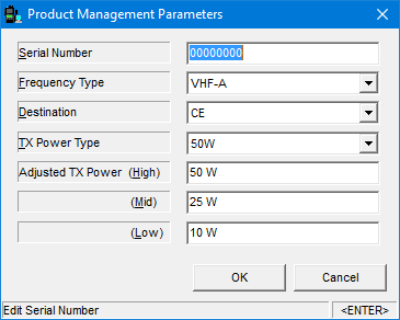
Change Frequency Type to VHF-A, and check the remaining settings are appropriate. Note that you may need to go back here later to re-enter the serial number (if you need that to be correct).
Hit ok, then hit Write To Radio, and answer Yes to the warning that shows up. This changes the hardware version.
Adjustment
To perform adjustments, launch the software with the /d flag. No password is needed.
Adjustments are done according to the service manual, but some changes should be made first:
Hit Dealer -> Alignment:
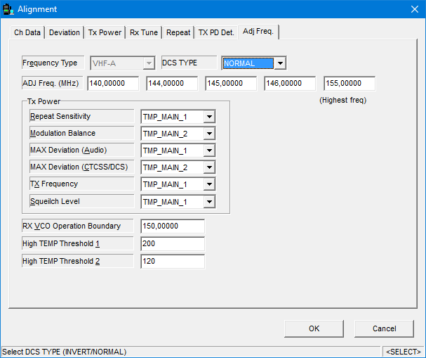
Change the ADJ Freq. fields to match this or something similar. This changes the spot frequencies where adjustments are performed later. You may want to change the RX VCO Operation Boundary to 150 MHz to avoid a locking issue in the 147-150 range.
Hit OK and exit alignment mode, and restart the repeater.
VCO Adjustment
You may have to adjust the VCO if unlocks are encountered or to help you sleep better.
Attach a meter to the top test point circled below that's inside the RF unit (just pull the top cover).
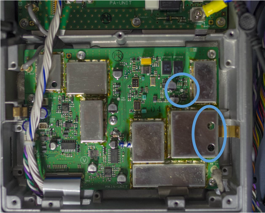
Then go to the Rx Tune menu in the Alignment mode, this lets you quickly set the frequency of the VCO:
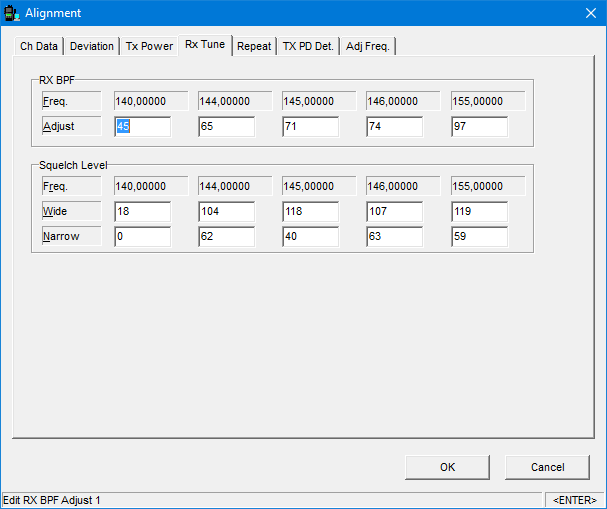
Select the 140 and 146 Adjust fields to set the frequency of the receiver, use a small flat heat screw driver/dedicated plastic trimmer to adjust the two VCO trim points.
The exact voltage you adjust to is not specified. I found that peaking the voltage would cause locking errors on some units. I adjusted for around 2 V at 146 MHz and checked for lock errors by injecting a moderately strong RF test signal at the frequency I was adjusting at. By listening to the sound you can hear if the VCO is having problems locking.
Check all test frequencies for locking issues before finishing this adjustment.
The top hole covers the lower range, while the bottom covers the high band VCO at 155 MHz.
You can stay in this menu as the next stage is sensitivity adjust.
Sensitivity
This adjustment can be done with the service manual spec, but a quick and dirty way to do it is to use a voltmeter with the RSSI output.
Connect the DVM between chassis and pin 8 in the D-Sub on the back:
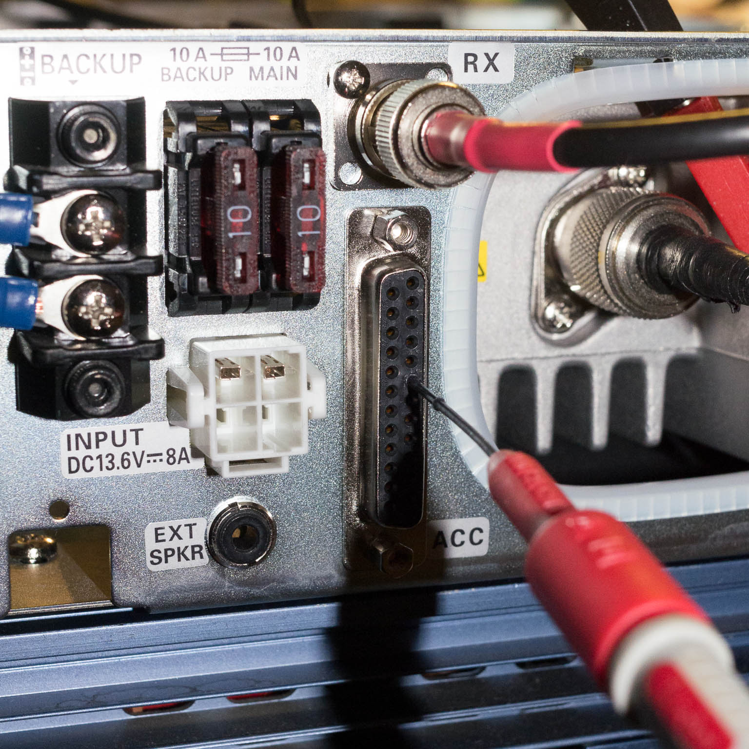
Select each frequency in the adjust menu and tune your test generator to that frequency in sequence, then adjust the values for maximum voltage at each frequency. Typically at the specified level, 0.8-0.95 V will be seen at –113 dBm input.
At this point the squelch will usually not open at all, setting the squelch levels to 255 will force it open and you can also hear the quieting when you get close.
Remaining adjustments
The following adjustments are now required:
- Squelch
- For ham use, ignore the levels specified, they are way too tight.
- Adjust the squelch to close around 8 dB SINAD and open at 12 dB SINAD.
- Otherwise everyone will make fun of you for having a shitty repeater.
- TX Power
- Adjust this to the levels set up earlier in Factory Mode
- TX Power Down detect
- If you adjusted for 5/10/25 W you need to adjust the PD level to 2.5 W or lower instead of 5 W.
- This adjustment sets the power threshold where the repeater thinks the PA is damaged; the adjustment power must be below the Low power adjusted power to avoid issues.
Do these according to the service manual.
The following adjustments are recommended:
- Deviation
- CTCSS deviation will definitely be off
- Repeat Sensitivity (unless you're using external control logic)
It might also be worthwhile to go through the normal settings such as power levels, button configurations, remote/local mode etc.
Finishing Up
Before exiting the adjustment mode, I recommend writing down or screenshotting each window in case something goes wrong with the write process.
When exiting the alignment mode, look at the display on the repeater to see if any error codes show up. If they do, then the writing of the new adjustments failed and you'll have to do them again.
Other Notes
The VXR-9000 has a basic logic built in and can do CTCSS controlled and 2/5-tone controlled repeater modes, as well as CWID. Unfortunately it can't do DTMF control so a proper repeater will need an external controller.
The standard programming when you launch the software is for a base station, and you need to set the mode of the repeater for each channel in use from B to R (repeater).
I recommend setting the channel setting Rev Bst to 120 when the repeater is set to use CTCSS on transmit, this enables the counter-phase burst at the end of transmission which closes the squelch in receivers much faster than normal and avoid the noise at the end of transmissions.
A previous version of the article specified 180° reverse burst; the recommended burst is 120°. This shift gives a quicker response in many CTCSS detectors, and has no significant downside for other types.
The power cable for the repeater is the same as the following radios: FT-450 FT-991 Kenwood TS-480 ICOM IC-7100 IC-7600.
There is also plenty of space for an AC/DC supply (13.8 V/10 A or so for the 25 W version) inside the chassis.
The repeater will go into a configurable mode when operating on backup power (alarms, low TX power, power save, etc.), so a full install should ideally use the main power plug instead of the backup.