VXR-9000 PA Failure, Fan Failure, Funky CTCSS, Fun PA De-Capping
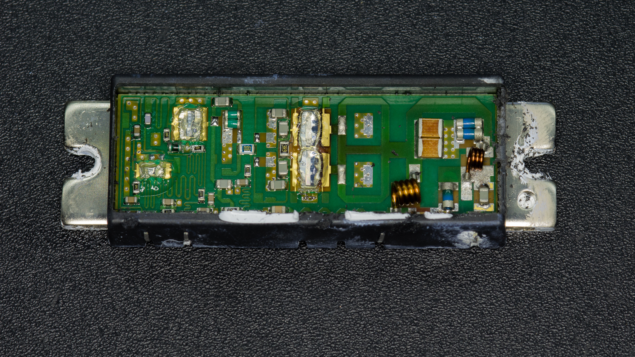
Recently we became aware of a failure in one of our VHF repeaters, users claimed the output power was significantly worse while the sensitivity was the same.
PA Failure, Fan Failure
During an initial field survey we noted the fan running continuously, but were primarily looking for antenna related issues. As neither me nor the other repeater manager knew the exact configuration of the repeater, the fan running was not seen as anything alarming.
During a second field survey we noted the repeater displaying the code E2, and that it was running quite hot (approx 50 °C). The fan had also stopped.
We brought the repeater back to the healing bench, and some symptoms were noted:
- Output power 10 W when cold
- Reduced to 4 W when heated
- The power should have been 50 W
- Fan was fine, power switch circuits were broken
- When powered off, the repeater still pulled around 2.5 A from the 14 V supply
As I had a spare repeater, the PA module was swapped over to the primary repeater and the problems went away. It was also noted that the output power was around 50 W after repairing the PA.
It's likely the PA failed due to overheating, as the VXR-9000 is not capable of 100% duty cycle at 50 W. Thermal oscillations likely caused the fan to switch on and off several times, due to a design issue with the fan switch circuits the switch transistors failed and seem to have burnt off the emitter-bond wires (it hard switches some high side PNP transistors into a 10'000 µF capacitor; not a good design at all).
I recommend running these repeaters at 25 W, and I adjusted the power levels in this unit to 25/10/5 W to avoid issues in the future.
I also recommend setting the fan to run continuously to avoid stressing the fan driver circuitry.
Funky CTCSS
This repeater station supports non-CTCSS users for legacy reasons (same reason it has 1750 Hz).
The control logic adds a CTCSS tone to all transmissions, however this configuration unfortunately didn't high pass filter the incoming audio (the logic has the CTCSS decoder in this case so it needs a full BW signal).
The effect of this is that when CTCSS was used to talk into the repeater, the new and original tones would sum at a random phase. This obviously caused CTCSS squelch to be unreliable since these can potentially cancel out.
PA De-Capping
I machined the top off the old PA module to see what was inside. The PA module used in this series (for all but the earliest versions) is a Toshiba S-AV32 60 W hybrid module.
As this is a fairly modern PA (2000s, this isn't RoHS compliant but later variants were) the risk of beryllium oxide is very small.
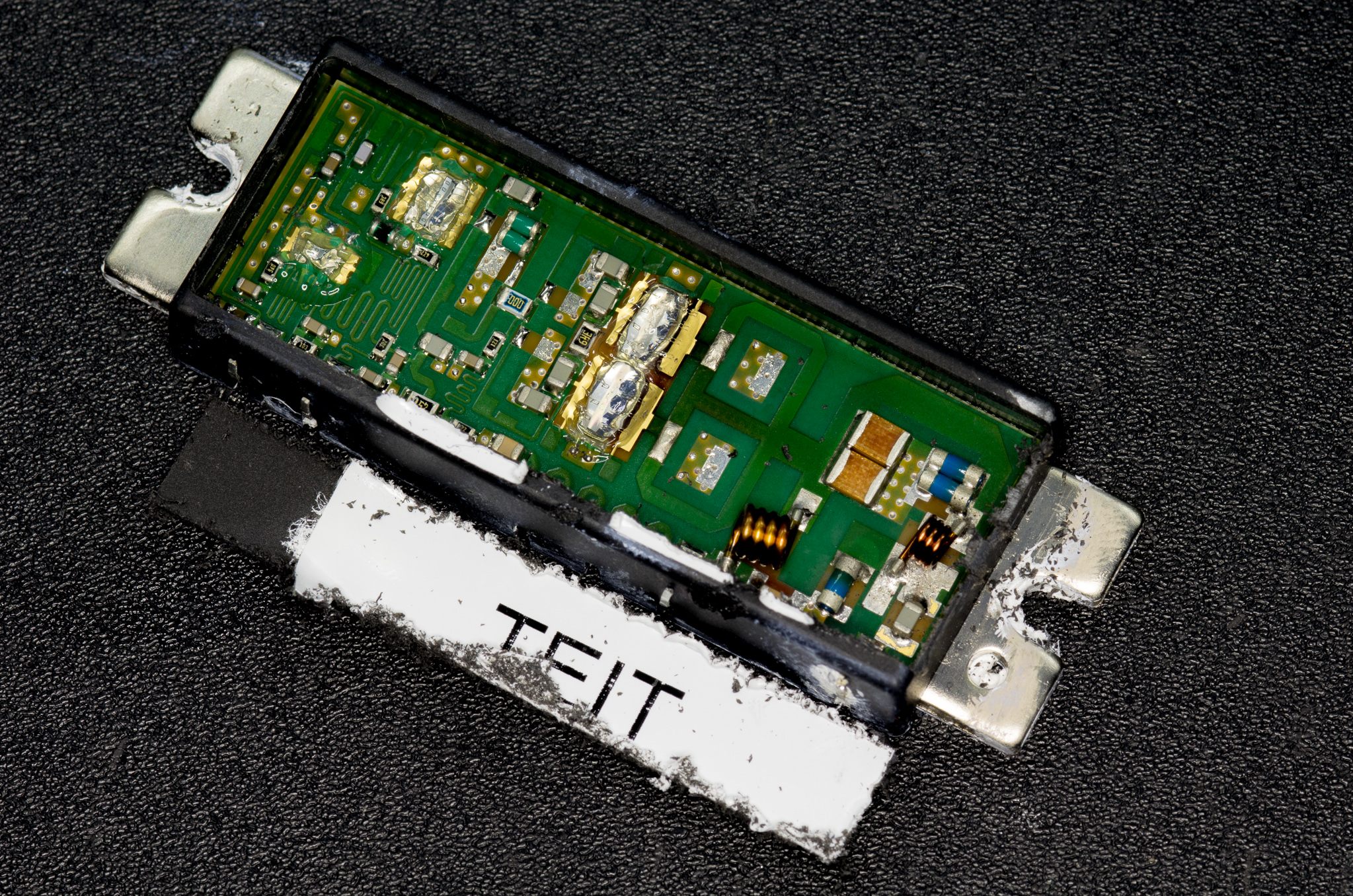
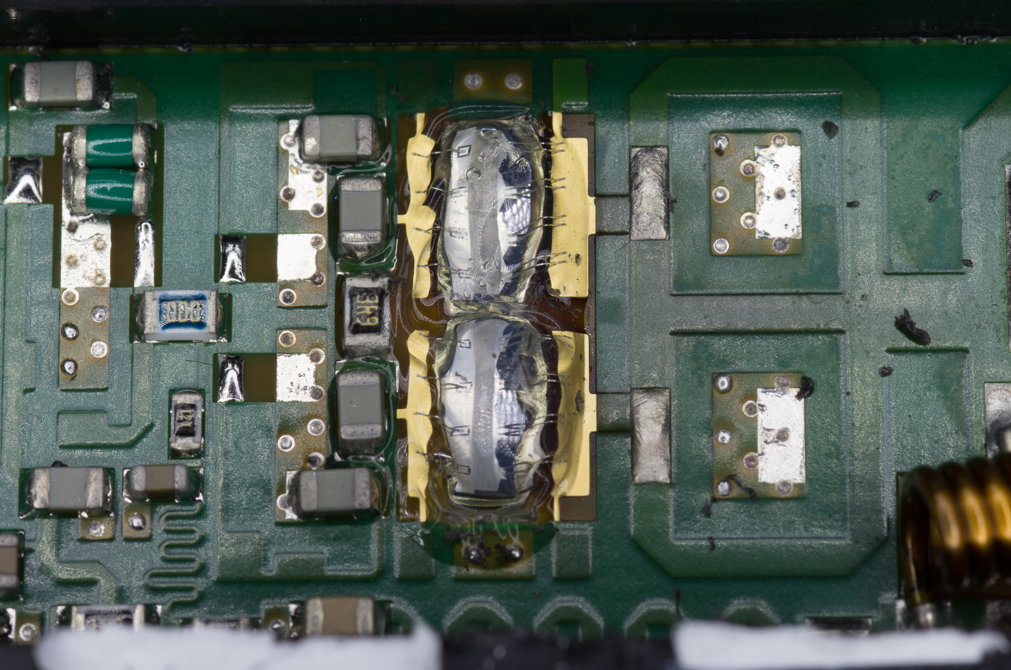
The input power is 50 mW, so this little module has a lot of gain built in, the transistors are wire-bonded to the board and covered with a very flexible potting compound. The dies are soldered directly to the aluminium heat spreader.
The PA transistors seem to be in parallel, there doesn't seem to be any balancing circuitry as the drains are connected together. I believe the pattern around the output would be too small to have any significant transmission line effects.
I wasn't able to spot anything that looked damaged under a normal 20x microscope.
Output Transistors
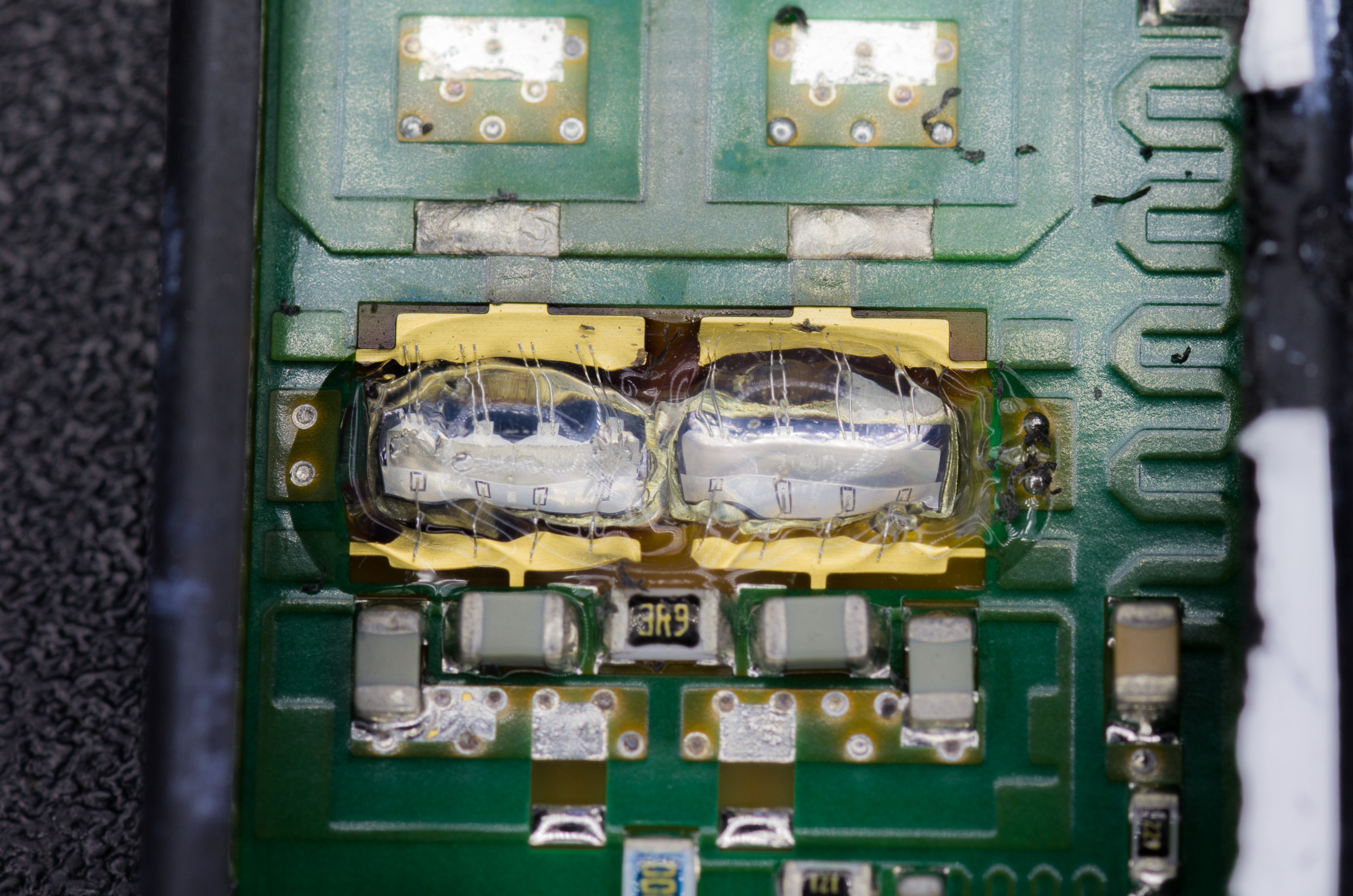
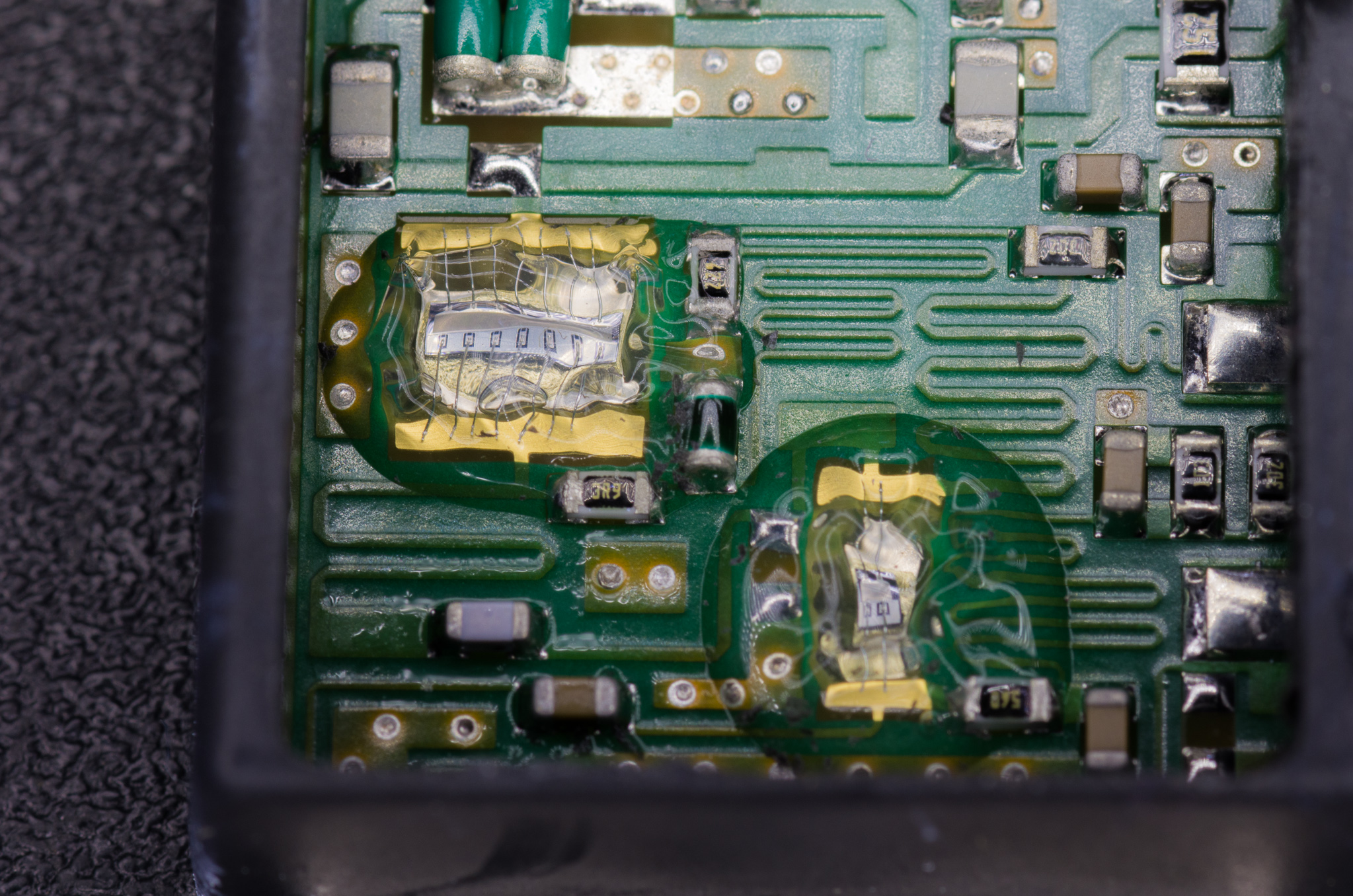
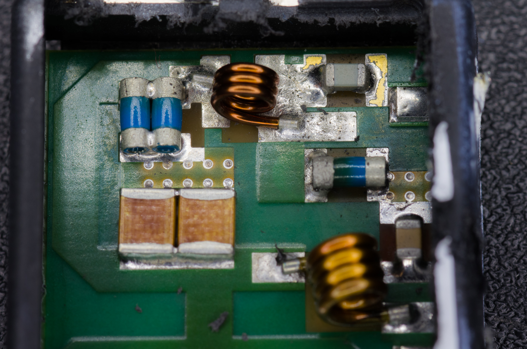
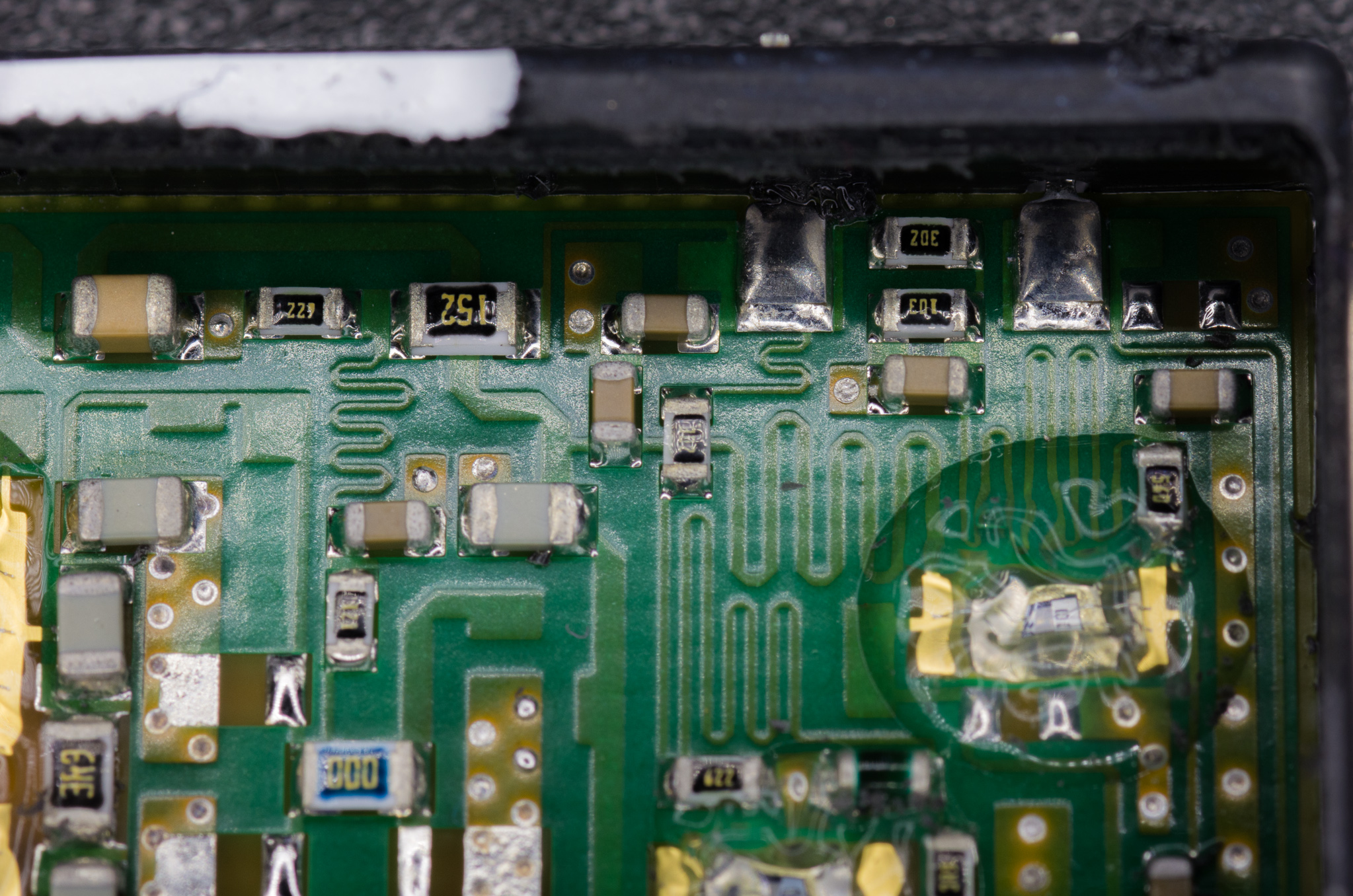
A destructive test showed the bottom output transistor was the likely cause; ripping the bond wires off that device got the DC current draw down to normal.
Also note that the MELF looking resistors are not standard parts, they're hollow tubes. The resistance for the output ones was around 0.5 Ω.
The various resistors are used to set the gate voltages of the transistors, these are all referred to an external VGG supply that is used for APC.
It's fairly easy to see that this is an LDMOS device based on the shape of the transistors.