Icom IC-775DSP LED Backlight Modification
I modified my IC-775DSP with backlighting and thought you might want to as well.
Introduction, Parts
The IC-775DSP like many radios of this vintage uses a CCFL backlight, this will obviously fail after some time and replacement parts are probably not available or may be undesirable in any case.
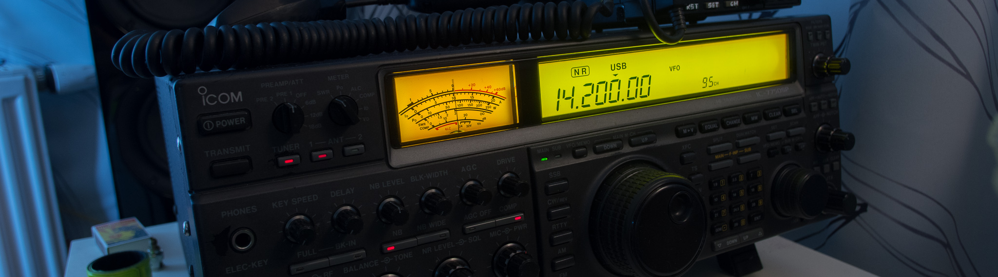
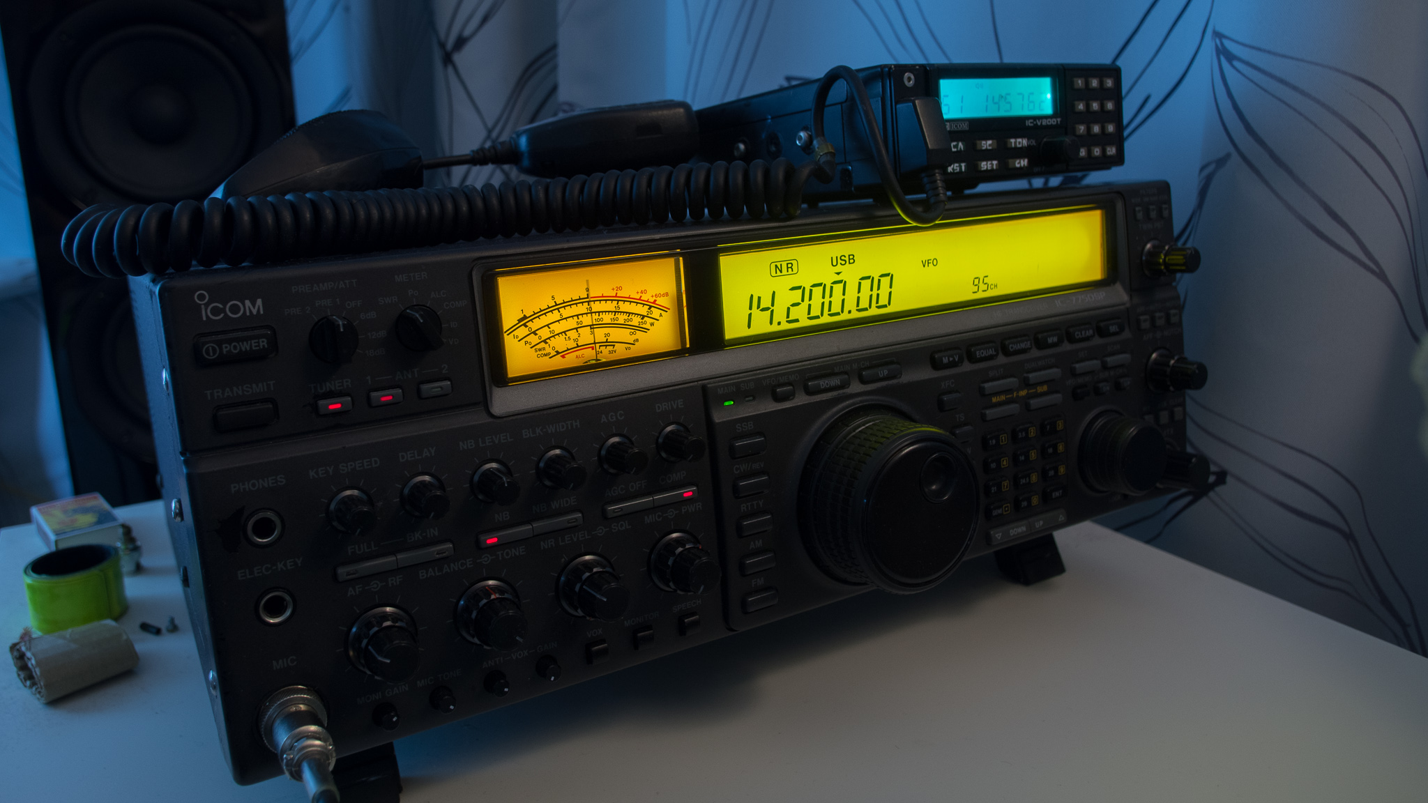
Note that in the picture above no processing was applied to make the lighting appear more even than it appears in real life. Overall brightness and contrast was adjusted as usual.
LED backlighting when done right looks beautiful, and I recommend implementing this mod.
The parts needed are approximately 30 cm of white LED strip. I used aluminium backed 5630 size cool white LEDs. These strips are very affordable and are available in a number of different voltage configurations, typically with 60 LEDs per meter or more. Each strip can support a very high output power and gives off a pretty decent 6000 K cool white light.
I used the "5 V" strip which is actually just parallel LEDs with no series resistance; this is not ideal but it was highly affordable in bulk and when driven right I've had no issues with them. If you're buying strips for this purpose I suggest getting 12 V strips.
If you use 5 V strips then you'll need a 7805 and some bypass caps, and for the direct LED drive a 10 Ω 1 W+ resistor is adequate.
Implementation
You'll need to remove the front panel, which is held in with 2 screws per side on all sides. After removing these there's a number of flat flex cables that have to come off, as well as the original CCFL drive cable.
To access the LCD module you'll need to remove the leftmost knob PCB, which is done by pulling off all the knobs from the front, undoing the nuts on the double stacked pots as well as a number of screws for the PCB.
Then it will be possible to remove the black LCD+S-meter assembly by undoing several other screws with small washers around it.
To remove the LCD PCB you have to unsolder the little PCB on the back of the S-meter first since the S-meter is glued in place. I replaced the PCB with a 0.1" header cable when reassembling to save me some effort if I had to go back in there.
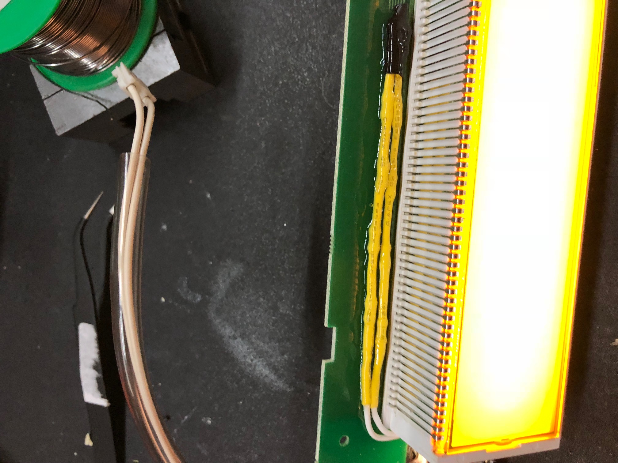
The LCD can now be removed from the black outer plastic case pretty easily. To remove the tube you can either desolder the LCD to remove it with the white plastic case, or just loosen the clips and wiggle it out after cutting the two leads. Be very careful with the white plastic as it's highly brittle from UV exposure, treat it like ceramic. Dispose of the tube according to local regulations, and be careful as it's quite long and thin.
Installing the LED is where I started taking pictures, so here are pictures showing the rest of the job:
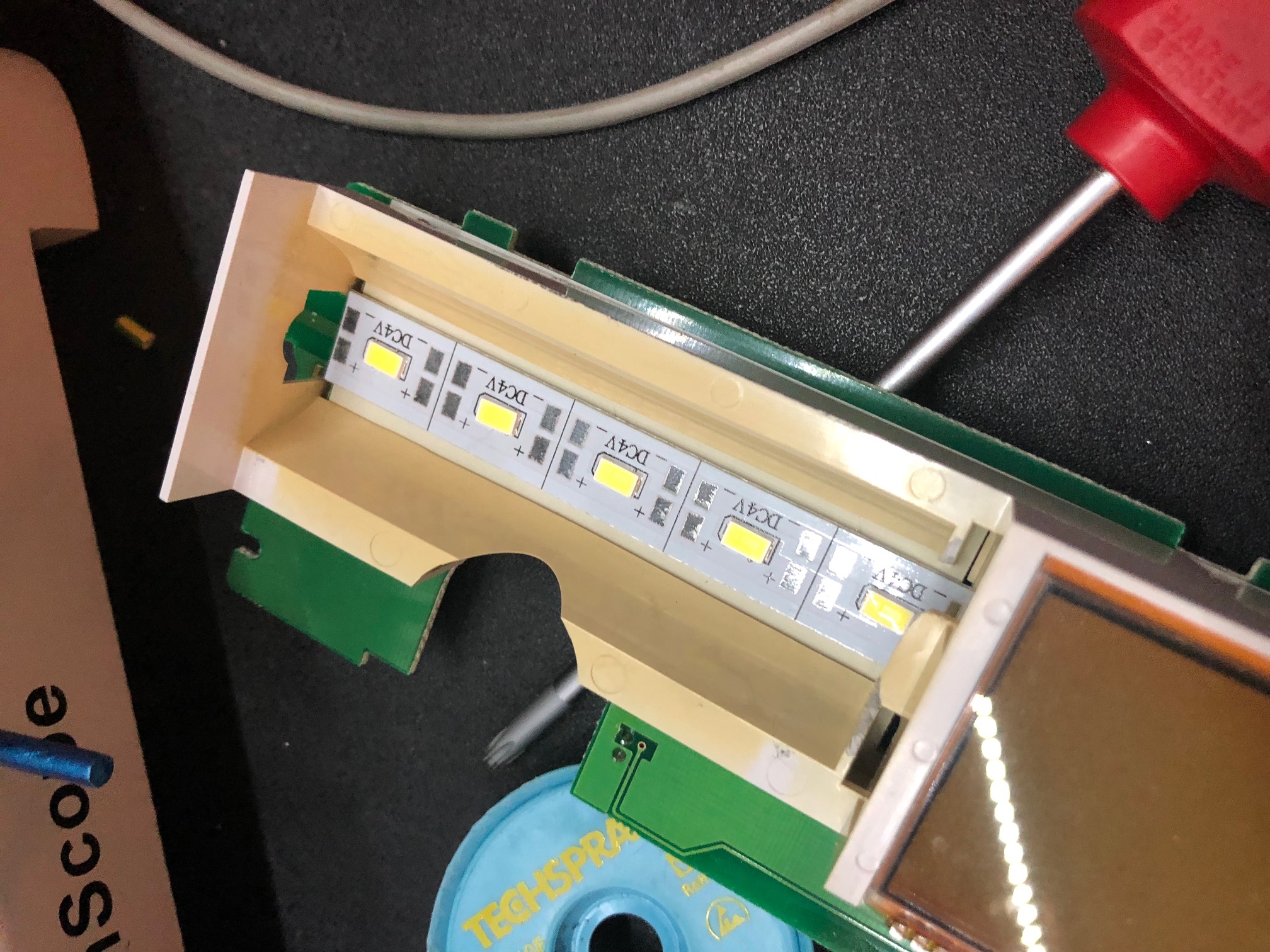
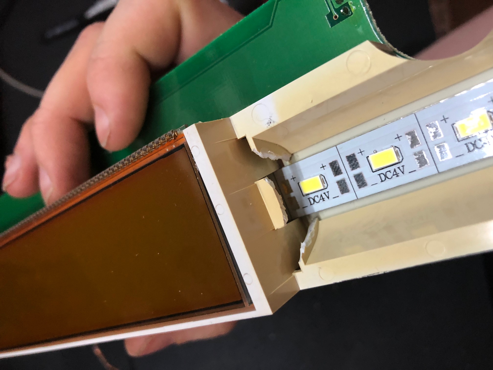
The LED strip can be slid in under the plastic shroud, and doesn't really need any fastening. I just put some super glue at the ends for good measure, this should be possible to crack off later if needed.
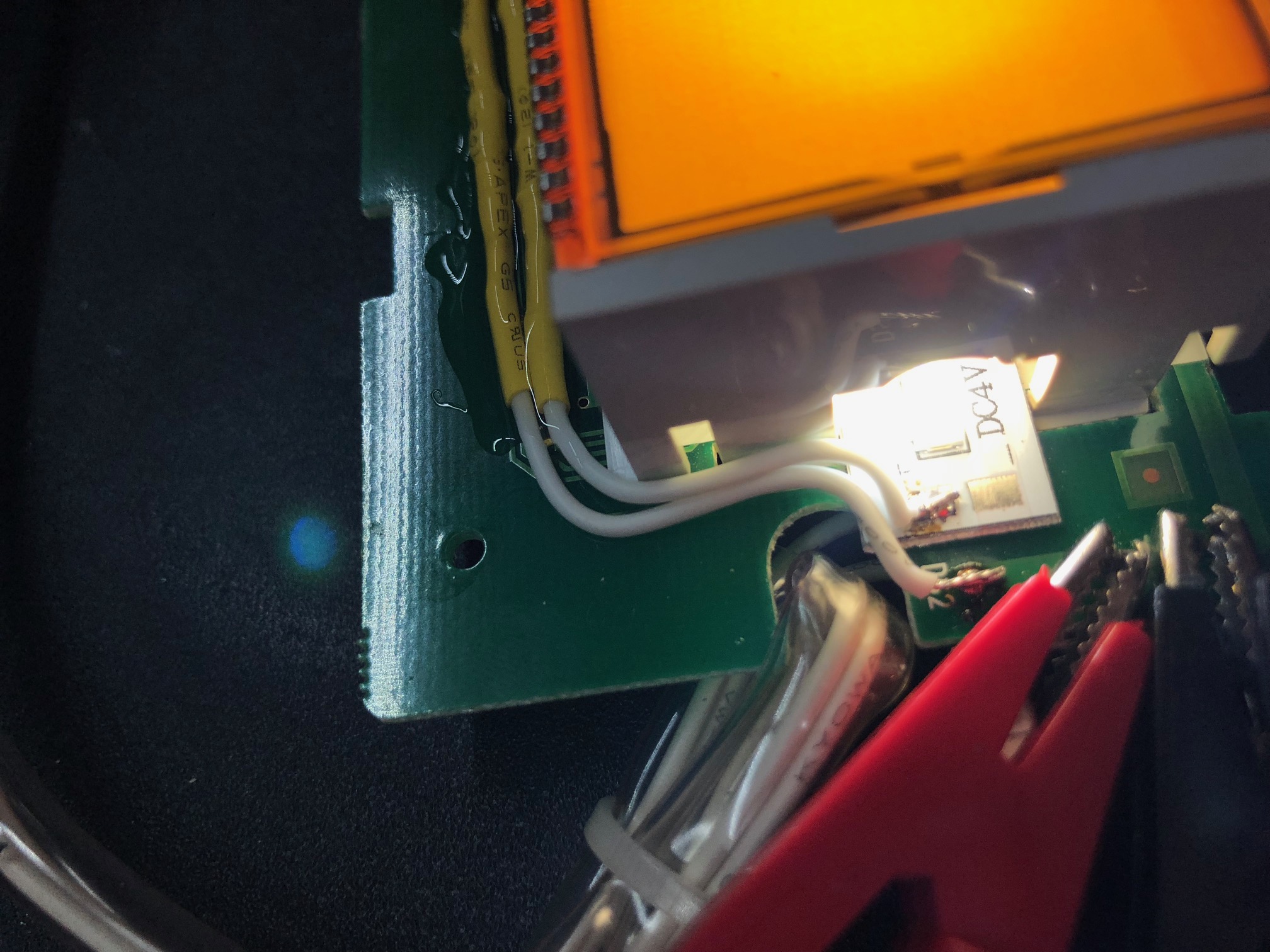
Note the connection to the positive near the CCFL plug, this is important for later.
For my LED strip I run it off 5 V and use a 10 Ω resistor to limit the current; this results in around 200 mA total strip current which is a nice bright level. Each LED of this size can handle around 100 mA, so they're being operated with a nice derating for a hopefully long life.
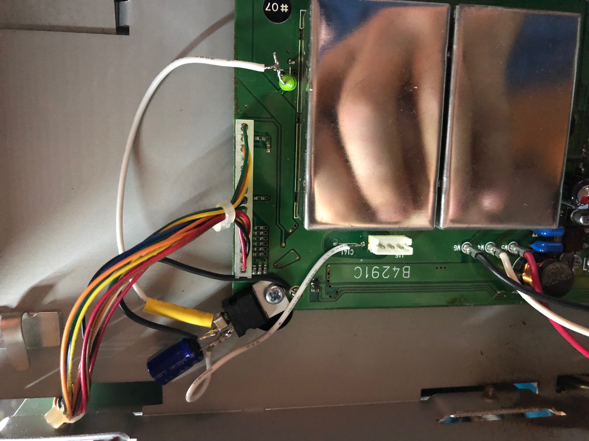
If you use a 12 V strip it can be powered off the 14 V rail directly. In any case we now need to disconnect the old CCFL inverter which is on the Main PCB right behind the front panel stuff.
The CCFL driver runs off 14 V through the green inductor shown below, cut the leg to get access to the 14 V rail and to disable the CCFL driver at the same time.
The blue capacitor near the CCFL connector is now the positive if you wired everything as shown above. The other pin is connected to ground. By removing the coupling cap you can solder a wire between the pin closest to the connector and your power supply.
If you used a 5 V strip then put a 7805 under one of the screws and wire that in series with the output. Note that I added decoupling capacitors to the input and output for stability. I also added a black wire to guarantee grounding of the regulator to avoid any surprises later. There's a tinned fiducial on the PCB that can be used for this purpose.